© 2016, IRJET | Impact Factor value: 4.45 | ISO 9001:2008 Certified Journal
| Page 1860
SMART STREET LIGHTING
Mrs.M.PriyaDharsini
1,M.Keerthana
2,R.Keerthana
3,V.Malarvizhi
4,G.Meen
a
51
M.PriyaDharsini
,
Assistant Professor/Department of IT,
1Sri Ramakrishna Engineering College,
Tamilnadu, India .
2
M.Keerthana,
3R.Keerthana,
4V.Malarvizhi,
5G.Meena
Students/Department Of IT,Sri Ramakrishna Engineering College,Tamilnadu,India.
Abstract :
The electric power in most of the countries inthe world is utilized in lighting the streets. However, the electrical energy consumed by street lights is not efficiently used because the need of street lamps is not essential in every street in all periods of time. In this paper, we propose a system that automatically switches off the light for the parts of the streets having no motion detection and turns on the light for the parts of streets where motion is detected when it is dark. The smart street lighting also controls the luminosity of light based on the motion and performs automatic light dimming which is an aspect that serves to reduce energy consumption. The intensity of light can be controlled based on the number of vehicles and the weather conditions. In the intension to efficient energy consumption solar energy is used instead of electrical energy. In this paper the LED lights are used to increase the lifetime of lamp.
Keywords: PIR sensor,MPLab,LED lights,PIC microcontroller 16F877A,solar power,LDR
1.INTRODUCTION
As the world is moving towards the smart
energy management, the system will require changes
© 2016, IRJET | Impact Factor value: 4.45 | ISO 9001:2008 Certified Journal
| Page 1861
light and solar energy paves the way for efficient
energy consumption.
A number of studies in recent research work
has focused on automatic ON and OFF of streets
lights. Some of the existing work related to Smart
Lighting concepts using sensors and Vehicular
Ad-hoc Networks(VANET) technology are briefly
discussed below.
In the Smart Lighting System[1], authors
Jorge Higuera et all focuses on the work of
interoperability and energy savings system in the
office room and is oriented toward the human centric
lighting studies. Samir A.Elsagheer Mohamed
researched Smart Street Lighting Control and
Monitoring System for Electrical Power Saving by
Using VANET[2].As networking concept is used,all
the wireless communications and the control signals
are not secured and authenticated. Rodrigo
Pantoni,Cleber Fonseca and Dennis Brandao
researched on Smart Lighting System Based on
Wireless Sensor Networks[3].This public lighting
system
provides
automation
for
control
process,diagnostics and alarms from possible failures
in the structure. However the system does not
concerns on monitoring efficient energy consumption
factors. In the work of Dae-Man Han and Jae-Hyun
Lim the Design and Implementation of Smart Home
Energy Management Systems based on ZigBee[4]
technology is performed. The Smart Home energy
management divides and assigns various home
network tasks to appropriate components. The
concept utilizes DMPR(Disjoint Multi Path Based
Routing in ZigBee sensor networks. The system uses
Photo Sensors and Occupancy sensors to control and
monitor the lights within the office room and aims at
saving energy. The paper on Internet of Things for
smart cities[6] by Andrea zanella, Lorenzo Vangelista
and their co-workers performs the work on smart
city concept and services which includes Structural
health of buildings, Waste Management, air quality,
Noise Monitoring, Traffic Congestion, City Energy
consumption and Smart Lighting .In the optimization
of street lighting efficiency the street light intensity is
controlled based on the weather conditions and the
presence of people.
The proposed work focuses on automatic
switches off of the lights for the parts of the streets
having no motion detection and turns on the light for
the parts of streets where motion is detected when it
is dark. The smart street lighting also controls the
luminosity of light based on the motion and performs
automatic light dimming which is an aspect that
serves to reduce energy consumption. The intensity
of light can be controlled based on the number of
vehicles and the weather conditions. In the intension
to efficient energy consumption solar energy is used
instead of electrical energy. In this paper the LED
lights are used to increase the lifetime of lamp.
© 2016, IRJET | Impact Factor value: 4.45 | ISO 9001:2008 Certified Journal
| Page 1862
SECTION 2: Proposed System
2.1 Primary Components
2.2 OBU Design
2.3 Work Flow
SECTION 3:
Result
SECTION 4: Conclusion
2.PROPOSED SYSTEM
2.1 PRIMARY COMPONENTS
PASSIVE INFRARED SENSOR:
A Passive InfraRed sensor (PIR sensor) is an electronic device that measures infrared (IR) light radiating from objects in its field of view. PIR sensors are often used in the construction of PIR-based motion detectors . Apparent motion is detected when an infrared source with one temperature, such as a human, passes in front of an infrared source with another temperature, such as a wall. When an object passes, the temperature at that point in the sensor's field of view will rise from room temperature to body temperature, and then back again. The sensor converts the resulting change in the incoming infrared radiation into a change in the output voltage, and this triggers the detection.
In this prototype, Passive Infrared sensor (PIR sensor) is used to detect the motion of the objects like vehicles, humans and pass it to the PIC microcontroller and the information is sent to the relay where the switch is set ON and streets lights will start glowing. When there is
no motion detected the switch is set OFF and street lights are in OFF condition.
PIC 16F877A PROGRAMMABLE
MICROCONTROLLER
The high performance of the PICmicro devices can be attributed to a number of architectural features commonly found in RISC microprocessors. These include Harvard architecture, Long Word Instructions, Single Word Instructions, Single Cycle Instructions, Instruction Pipelining, Reduced Instruction Set, Register File Architecture , Orthogonal (Symmetric) Instructions. General purpose I/O pins can be considered the simplest of peripherals. The direction of the I/O pins (input or output) is controlled by the data direction register, called the TRIS register. TRIS<x> controls the direction of PORT<x>. A ‘1’ in the TRIS bit corresponds to that pin being an input, while a ‘0’ corresponds to that pin being an output.
If pins are multiplexed with LCD driver segments, then on a Power-on Reset these pins are configured as LCD driver segments, as controlled by the LCDSE register. To configure the pins as a digital port, the corresponding bits in the LCDSE register must be cleared. Any bit set in the LCDSE register overrides any bit settings in the corresponding TRIS register.
© 2016, IRJET | Impact Factor value: 4.45 | ISO 9001:2008 Certified Journal
| Page 1863
PORTB and the TRISB Register
PORTB is an 8-bit wide bi-directional port. The corresponding data direction register is TRISB. Setting a bit in the TRISB register puts the corresponding output driver in a high-impedance input mode. Clearing a bit in the TRISB register puts the contents of the output latch on the selected pin(s).
PORTC and the TRISC Register
PORTC is an 8-bit bi-directional port. Each pin is individually configurable as an input or output through the TRISC register. PORTC pins have Schmitt Trigger input buffers.
When enabling peripheral functions, care should be taken in defining TRIS bits for each PORTC pin. Some peripherals override the TRIS bit to make a pin an output, while other peripherals override the TRIS bit to make a pin an input.
Fig 2: Pin out diagram of PIC 16F877A
FEATURES
2 PWM 10 bit
256 Bytes EEPROM data memory
ICD
25mA sink/source per I/O
Self Programming
Parallel Slave port
LIQUID CRYSTAL DISPLAY
A liquid-crystal display (LCD) is a flat panel display,
electronic visual display, or video display that uses the light modulating properties of liquid crystals. Liquid crystals do not emit light directly. They use the same basic technology, except that arbitrary images are made up of a large number of small pixels, while other displays have larger elements. Its low electrical power consumption enables it to be used in battery-powered electronic equipment.
© 2016, IRJET | Impact Factor value: 4.45 | ISO 9001:2008 Certified Journal
| Page 1864
Fig 3: Schematic Diagram for LCDThe three control lines are referred to as EN, RS, and RW. Then EN line is called “Enable”. This control line is used to tell the LCD that you are sending it data. The enable pin used by the LCD latches the information presented to it’s data pines. When data is supplied to data pins, high to low pulse must be applied to this “EN” pin in order to latch the data present at the data pins. This pulse must be a minimum of 450 ns wide.
The RS line is the “Register Select” line. When RS is low (0), the data is to be treated as a command or special instruction (such as clear screen, position cursor, etc..). When RS is high (1), the data being sent is text data, which should be displayed on the screen. The RW line is the “Read/Write” control line. When RW is low (0) the information on the data bus is being return to the LCD, When RW is high (1), the program is effectively querying ( or reading) the LCD.
Code(HEX) Command to LCD instruction register
1 Clear display of the screen 38 2 line. 5X7 Matrix
80 Force cursor to begin from 1st line
C0 Force cursor to begin from 2nd line Tab 1: LCD Command codes
RELAY AND DRIVER CIRCUIT
A Relay is an electrical switch that opens and closes under the control of another electrical circuit. In the original form, the switch is operated by an electromagnet to open or close one or many sets of contacts. Because a relay is able to control an output circuit of higher power than the input circuit, it can be considered, in a broad sense, to be a form of an electrical amplifier. Relays are components which allow a low-power circuit to switch a relatively high current on and off, or to control signals that must be electrically isolated from the controlling circuit itself.
To make a relay operate, you have to pass a suitable pull-in and holdpull-ing current (DC) through its energizpull-ing coil. And generally relay coils are designed to operate from a particular supply voltage - often 12V or 5V, in the case of many of the small relays used for electronics work. In each case the coil has a resistance which will draw the right pull-in and holding currents when it is connected to that supply voltage. So the basic idea is to choose a relay with a coil designed to operate from the supply voltage for the control circuit and then provide a suitable relay driver circuit so that the low-power circuitry can control the current through the relay coil.
LIGHT DEPENDENT RESISTOR
LDRs or Light Dependent Resistors are very useful especially in light/dark sensor circuits. Normally the resistance of an LDR is very high, sometimes as high as 1000 000 ohms, but when they are illuminated with light resistance drops dramatically.
© 2016, IRJET | Impact Factor value: 4.45 | ISO 9001:2008 Certified Journal
| Page 1865
to pass through it. When a light level of 1000 lux (bright light) is directed towards it, the resistance is 400R (ohms).When a light level of 10 lux (very low light level) is directed towards it, the resistance has risen dramatically to 10.43M (10430000 ohms).
[image:6.612.325.512.290.514.2]
Fig 4:Working of LDR
When the light level is low the resistance of the LDR is high. This prevents current from flowing to the base of the transistors. Consequently the LED does not light. However, when light shines onto the LDR its resistance falls and current flows into the base of the first transistor and then the second transistor.
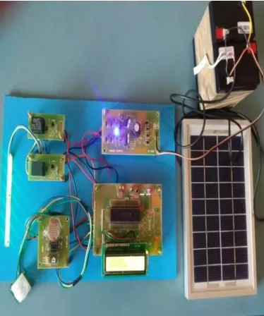
2.2 OBU DESIGN
The proposed circuit consists of PIC16F877A microcontroller, PIR sensor, light dependent resistor and Liquid Crystal Display. Passive Infrared sensor, also called as PIR sensor is connected to the PD0 pin of the microcontroller. PIR sensor senses the motion of the objects. The PIR sensor internally will have an IR detector. Different objects will emit IR rays of different wavelength. These rays were detected by the PIR sensor. PIR is initially
high and is set to low automatically after sometime. Whenever it detects the motion of any object, it becomes low. LDR is connected to the ADC pin – ADC0 of the microcontroller as LDR will produce analog value which is converted to digital by the ADC.Light dependent resistors will have low resistance in light and high resistance in dark. The resistance of Light dependent resistor in dark is in range of ohms and in dark its resistance is in the range of mega ohms. When the light falls on LDR it resistance is reduced to a great extent.
Fig 5:On Board Unit diagram
2.3 WORK FLOW
© 2016, IRJET | Impact Factor value: 4.45 | ISO 9001:2008 Certified Journal
| Page 1866
high the street light intensity is adjusted and the street light undergoes the process of adaptive dimming. PIR sensor senses the motion of the objects. The PIR sensor internally will have an IR detector. Every object in the world radiates some IR rays. These are invisible to the human eye but electronic components can detect them. Different objects will emit IR rays of different wavelength. These rays were detected by the PIR sensor. PIR is initially high and is set to low automatically after sometime. Whenever it detects the motion of any object, it becomes low. Light dependent resistors will have low resistance in light and high resistance in dark. The resistance of Light dependent resistor in dark is in range of ohms and in dark its resistance is in the range of mega ohms. When the light falls on LDR it resistance is reduced to a great extent.
Fig 6: Block diagram
PROCESS OF GENERATING SOLAR ENERGY:
Solar photovoltaic module is used in the process of converting solar radiation (sunlight) into electricity using a device called solar cell.
Step1: Solar panels contain photovoltaic cells(solar cells),which is a semiconducting device made of silicon generates electricity when exposed to light.
Step2: The generated electricity from the solar panel is then gone through Solar Charge Controller which is used for battery charge regulation.
Step3: The Direct current (DC) power generated is then stored in the battery storage system.
Step4: As the electronic devices used in the Smart street lighting works on direct current, the energy from the battery is supplied to the system directly otherwise the DC power is converted to the alternate current(AC) by inverter.
PROCESS OF MOTION DETECTION:
Passive InfraRed sensor (PIR sensor) is an electronic device that measures infrared light radiating from objects in its field of view by which the motion of the object is detected.
Step1: PIR sensor is used to detect the motion of the objects like vehicles, humans and pass it to the PIC microcontroller.
SOLAR POWER SUPPLY
PIC16F877A
MCU
MOTION DETECTION SENSOR
LUMINANCE SENSOR
LCD DISPLAY
RELAY DRIVER UNIT
© 2016, IRJET | Impact Factor value: 4.45 | ISO 9001:2008 Certified Journal
| Page 1867
Step2: The information from the PIC 16F877A is sent to the relay where the switch is set ON and streets lights will start glowing.
Step3: When there is no motion detected the switch is set OFF and street lights are in OFF condition.
PROCESS OF INTENSITY CONTROL:
Light dependent resistor(LDR) is used in the process of measuring the intensity of the environment around and it also involves in the controlling of the intensity of the street lights.
Step1 : LDR is an electronic device where the resistance of the LDR is very high but when they are illuminated with light, resistance drops dramatically.
Step2 : When the resistance drops, the flow of the current to the LED varies and the light glows in correspondence to the environment brightness.
Step3 :After the detection of the object, the light will switch ON and using LDR the luminosity of the
environment is measured by which it can control the intensity of light.
Step4 : If the luminosity measurement in the surrounding is high(say above 100 lux) the LED street lights doesn’t glow. If the luminosity measurement is at medium level(say 25 to 100 lux) the LED glows dim and if the luminosity level is below 25 lux the street light glows bright.
RESULT:
PIC microcontroller 16F877A is used in controlling the smart street lighting system. The information gathered from the PIR sensor and the LDR is sent to the PIC and the PIC in turn controls the relay and driver circuit which is used in the automatic switching control and adaptive dimming of the LED street lights. The electric power is generated from the solar panel which is stored in the lithium battery and the DC current stored in battery is used for the electronic devices in the system.
CONCLUSION:
Smart street lighting consumes the energy efficiently with the help of solar panel. It also reduces the manual work of controlling the lighting systems. Motion detection of the object is made and the street lights are switched ON and OFF according to that. If the motion is detected the lights are made ON otherwise the lights are set OFF. Luminosity measurement is made by LDR and the intensity of the street light is controlled so the power is utilized only when it is essential. LED lights have more lifetime than HPS lights. This system is comparatively cost efficient and reliable.
REFRENCES:
[1] Rodrigo Pantoni,“Street lighting system based on wireless sensor networks”,INTECH open science and Minds,2012
© 2016, IRJET | Impact Factor value: 4.45 | ISO 9001:2008 Certified Journal
| Page 1868
[3] Jorge Higuera , “Smart Lighting System”, IEEE sensors Journal,Vol.15,No.2,May 2015.
[4] Dae-Man Han and Jac-Hyun Lim “Design and Implementation of Smart Home Energy Management Systems based on ZigBee”,IEEE,2010.
[5] Andrea Zanella and Lorenzo Vangelista “ Internet of Things for Smart Cities”,IEEE Internet of Things Journal,Vol.1,No.1,Febrauary 2014.