© 2016, IRJET | Impact Factor value: 4.45 | ISO 9001:2008 Certified Journal | Page 801
Experimental Investigation of Damping characteristics for various
Damping Materials
Jilani Shaik
1, Sd.Abdul kalam
2, P.Ravi kumar
31
Department of Mechanical Engineering (Machine Design), PVPSIT, Kanuru, Vijayawada
2
Assistant Professor, Department of Mechanical Engineering, PVPSIT, Kanuru, Vijayawada
3
Assistant Professor, Department of Mechanical Engineering, PVPSIT, Kanuru, Vijayawada
---***---Abstract - The basic purpose of damper is to reduce the
vibration and to have a better comfort and safety. The characteristic of damping system has an important influence on its design and overall performance of the system. In this paper magnetic damping effect is considered for characterization. Hence in order to design damping systems determination of damping coefficients is necessary. This effect is the most recently used due to their low price and high reliability. An experiment has been conducted to establish the behavior of magnetic damper. The damping materials are water, magnet and SAE 40 grade oil used for characterizing the vibration behavior. The amplitude Verses frequency response curves are plotted for above damping materials. .
Key Words
:
Damping coefficient, Frequency ratio,Amplitudes, Natural frequency
1. INTRODUCTION
Damping can be defined as dissipation of
oscillating energy. Oscillating energy includes
vibration, noise and shock waves. Passive suspension
systems are most commonly used damping systems
because of their low price and high reliability.
The goal is to investigate characteristics of the
damper for a single degree of freedom system, analyses
under harmonic excitation of the base. The magnetic
dampers are now being effectively deployed as
vibration dampers in the suspension system to
enhance the comfort and safety.
The damping in a system can be obtained from
free vibration decay curve. Where the free vibration
test is not practical, the damping may be obtained from
the frequency response curve of forced vibration test.
Fischer and Isermann[1] have shown how each
part in a vehicle suspension use as ride comfort in
dynamic model. Lin and Kanellakopoulos[2] shows
system can have dual purpose of comfort and safety. Xu
shows[3] how vibration of parts can effect the
mechanism. Ebrahimi, Khamesee and Golnaraghi [4]
demonstrate passive damping can be achieved by
addition of viscous fluid to the active damper, which
guaranties a failsafe damper in case of power failure.
The electromagnetic dampers have lesser reliability
because of dependence on external power source and
higher weight. Lee, Park, Min and Chung[5] shows how
to control seismic response of building structures using
tuned liquid damper. Yau and Chen[6] shown vibration
suppressing system using electric- hydraulic actuator
design using squeeze film damper. Lee and Jee[7] the
vibration of a flexible cantilever beam using active
piezoelectric type servo damper to suppress both small
and large amplitude vibrations. Martins et
al[8]proposed a new hybrid damper design for vehicle
suspension application. Linear actuator was the active
unit and the hydraulic passive damping effect as a
passive part. Lin and Roschke and Loh [9]proposed a
hybrid base isolation with MR dampers, and showed
that a combination of high damping rubber bearing
isolators and MR damper can provide robust control of
vibration for large civil engineering structures from a
wide range of seismic events
.
2. MODELING OF FABRICATED DAMPER AND
EXPERIMENTAL SET UP
© 2016, IRJET | Impact Factor value: 4.45 | ISO 9001:2008 Certified Journal | Page 802
rpm). A mechanical recording device is mounted on framewhich records the amplitude of vibration of system.
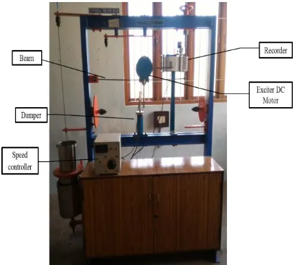
[image:2.595.54.272.258.451.2]The cantilever structure with attached mass is the most widely used configuration for spring mass device. The stiffness of the structure depends on the loading condition, material, and cross sectional area perpendicular to the direction of vibration. Passive system is the most used type in automobile suspensions. The main reasons are the simplicity, low cost and reliability of this solution. A spring and damper compose this suspension system, both fixed between the wheel supporting structure (unsprung mass) and the beam (sprung mass).
Figure - 1.Experimental Setup
2.1 Magnetic Damper
Two permanent magnets of diameter 5cm are taken one magnet is fixed to the cylinder at bottom and other magnet is connected to the system top surface. The cylinder and piston is arranged like such that poles of the both magnets are faced together. When beam vibrates the beam pushes the piston downwards. When the piston comes nearer to the cylinder bottom surface due to like pole magnet fixed at the bottom surface a repulsive force exerts on the piston. This automatically controls the level of vibration.
The damping coefficient is found for this magnetic damper through the experiment and it is compared with the other existing dampers.
3.
Analytical Formulae
The governing equation of motion of spring mass system
mẍ + cẋ + k=0
In the case of cantilever beam we first calculated moment of inertia of the beam by taking length, thickness,
and width of the beam. Moment of inertia for a rectangular cross-section can be obtained from the expression
Moment of inertia for the beam
Using mass equivalent and stiffness of beam and spring, we can calculate natural frequency of the system having Static deflection of 25mm.
Mass equivalent of the system Spring stiffness
Beam stiffness
Equivalent stiffness
Natural frequency of the system
Angular velocity of the system
Harmonic force is given to the beam via exciter. The time period is noted based on the time period the damping coefficients are determined. Experimental values of time period for damped oscillation system observed.
Damped natural frequency of the system
From above equation we calculated ζ, then we calculate damping coefficient
Damping coefficient
The steady state amplitude ‘X’
© 2016, IRJET | Impact Factor value: 4.45 | ISO 9001:2008 Certified Journal | Page 803
Table -1: Damping Coefficients at different deflectionsDamping materials
Deflections in mm Average values
25 20 15 10
Water 0.33 0.273 0.24 0.211 0.2635
Magnet 0.5329 0.4841 0.4687 0.3715 0.4643
SAE 40 oil 0.8012 0.7695 0.6513 0.4100 0.657
4. Results and Discussion
[image:3.595.308.558.99.317.2]The Natural frequency of the system is 30.1475
rad/sec.Table- 2: Speed, frequency ratio, Dimensionless amplitude values for Water, Magnet and Oil
Speed in
rpm ω ω/ω
n
x/(moe/m)
Water Magnet Oil 100 10.472 0.347 0.134 0.128 0.121 150 15.708 0.52 0.348 0.31 0.271 200 20.944 0.694 0.76 0.583 0.459 250 26.179 0.867 1.45 0.893 0.645 280 29.321 0.972 1.835 1.044 0.739 300 31.415 1.041 1.954 1.117 0.791 320 33.51 1.111 1.958 1.166 0.834 330 34.557 1.145 1.931 1.183 0.853 340 35.604 1.18 1.894 1.196 0.87 350 36.651 1.215 1.85 1.205 0.886 360 37.699 1.249 1.804 1.211 0.899 370 38.746 1.284 1.758 1.214 0.912 400 41.887 1.388 1.631 1.213 0.941 420 43.982 1.458 1.559 1.207 0.956 440 46.076 1.527 1.498 1.198 0.968 470 49.218 1.631 1.422 1.183 0.981 480 50.265 1.666 1.401 1.178 0.984 520 54.454 1.805 1.329 1.158 0.994 530 55.501 1.84 1.314 1.153 0.996 570 59.69 1.978 1.264 1.136 1.002 590 61.784 2.048 1.244 1.128 1.004 610 63.879 2.117 1.225 1.12 1.005 620 64.926 2.152 1.217 1.117 1.006 630 65.973 2.187 1.209 1.113 1.006 660 69.115 2.291 1.188 1.104 1.008
670 70.162 2.326 1.182 1.101 1.008 710 74.351 2.465 1.159 1.091 1.009 770 80.634 2.673 1.133 1.078 1.009 800 83.775 2.777 1.122 1.072 1.009
Graph- 1: Dimensionless amplitude v/s Frequency ratio for combined Water, Magnet and Oil
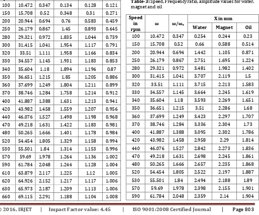
Table-3: Speed, Frequency ratio, amplitude values for water, magnet and oil
Speed in
rpm ω ω/ωn
X in mm
Water Magnet Oil 100 10.472 0.347 0.254 0.244 0.23
150 15.708 0.52 0.66 0.588 0.514
200 20.944 0.694 1.442 1.105 0.871 250 26.179 0.867 2.751 1.695 1.224 280 29.321 0.972 3.481 1.982 1.402 300 31.415 1.041 3.707 2.119 1.5 320 33.51 1.111 3.715 2.213 1.583 330 34.557 1.145 3.664 2.245 1.619 340 35.604 1.18 3.593 2.269 1.651
350 36.651 1.215 3.51 2.286 1.68
360 37.699 1.249 3.423 2.297 1.707 370 38.746 1.284 3.336 2.304 1.73 400 41.887 1.388 3.095 2.302 1.786 420 43.982 1.458 2.958 2.29 1.814 440 46.076 1.527 2.842 2.273 1.836 470 49.218 1.631 2.698 2.245 1.861 480 50.265 1.666 2.657 2.235 1.868 520 54.454 1.805 2.522 2.197 1.887
530 55.501 1.84 2.494 2.188 1.89
[image:3.595.42.569.361.798.2]© 2016, IRJET | Impact Factor value: 4.45 | ISO 9001:2008 Certified Journal | Page 804
610 63.879 2.117 2.325 2.126 1.907620 64.926 2.152 2.309 2.119 1.908 630 65.973 2.187 2.294 2.113 1.909 660 69.115 2.291 2.254 2.095 1.912 670 70.162 2.326 2.242 2.089 1.912 710 74.351 2.465 2.199 2.069 1.914 770 80.634 2.673 2.149 2.045 1.914 800 83.775 2.777 2.129 2.034 1.914
[image:4.595.316.550.284.399.2]Graph -2: Amplitude v/s Frequency ratio values for combined Water, Magnet and Oil
Table -4: Theoretical and Experimental amplitude values for Water
Water Speed
in rpm ω/ωn
X in mm
Theoretical Experimental
250 0.867 2.751 2.5
280 0.972 3.481 3
300 1.041 3.707 3.5
350 1.215 3.51 3
400 1.388 3.095 2.8
470 1.631 2.698 2.5
530 1.84 2.494 2
Fig.2a
Fig.2b
Fig.2c
Figure -2: Experimental amplitude values for water
Some of the experimental values of water at speeds 250(fig.2a), 350(fig.2b),470 (fig.2c)rpm and amplitudes 2.5mm, 3mm, 2.5mm respectively
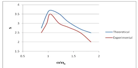
Graph -3: Amplitude v/s Frequency ratio values for Water
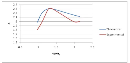
Table -5: Theoretical and Experimental amplitude values for Magnet
Magnet Speed
In rpm ω/ωn
X in mm
Theoretical Experimental
280 0.972 1.982 1.8
320 1.111 2.213 2
370 1.284 2.304 2.3
400 1.388 2.302 2.3
570 1.978 2.155 2
620 2.152 2.119 2
Fig.3a
© 2016, IRJET | Impact Factor value: 4.45 | ISO 9001:2008 Certified Journal | Page 805
Fig.3cFigure -3: Experimental amplitude values for Magnet
Some of the experimental values of magnet at speeds 280(fig.3a), 400(fig.3b),, 620(fig.3c) rpm and amplitudes 1.8mm, 2.3mm, 2mm respectively.
[image:5.595.50.274.225.334.2]Graph -4: Amplitude v/s Frequency ratio values for Magnet
Table -6: Theoretical and Experimental amplitude values for Oil
Oil Speed
In rpm ω/ωn
x in mm
Theoretical Experimental
250 0.867 1.214 1
280 0.972 1.402 1
300 1.041 1.5 1.2
350 1.215 1.68 1.5
400 1.388 1.786 1.5
520 1.805 1.887 1.8
570 1.978 1.901 1.8
Fig.4a
Fig.4b
Fig.4c
Figure -4: Experimental amplitude values for Oil
Some of the experimental values of oil at speeds 250(fig.4a), 350(fig.4b),570 (fig.4c) rpm and Amplitudes 1mm, 1.5mm, 1.8mm respectively.
Graph -5: Amplitude v/s Frequency ratio values for Oil
5. Conclusion
Damping characteristics for damping materials are observed. For all types of damping materials, same features of system were used and then analyzed.
Experiment conducted on VIB-LAB equipment. Damping coefficient C, displacement amplitude x and frequencyω/ωn are investigated. Damping ratio ζ value less than 1 hence this is under damped system.
Magnetic damper is proposed to suppress the vibrations at the free end of a cantilever beam. The experiment reveals that the proposed magnetic damper is effectively control the vibration. Variation of amplitudes of vibration at different speeds for the magnetic damper was found. The damping coefficient of the magnetic damper is C=143.96 Ns/m and Damping ratio ζ = 0.4643. After comparison of oil, water and magnet the one control of vibration lies between water and oil for the provided magnetic damper. Magnetic damper does not require lubrication and maintenance is less. Effectiveness of damper can be improved by providing electromagnetic damper.
6. References
1. D. Fischer, R. Isermann, Mechatronic semi active and active vehicle suspensions. Control Eng Pract. 12, 1353-1367 (2004)
2. J.S. Lin, I. Kanellakopoulos, in Nonlinear Design of Active Suspensions. 34th IEEE conference on Decision and control.(New Orleans, LA, 11-13 Dec 1995)
3. M. Xu, Impact testing and its appilications, part II. Shock Vib.29(4), 8-14 (1997)
© 2016, IRJET | Impact Factor value: 4.45 | ISO 9001:2008 Certified Journal | Page 806
Damper for Automotive Suspension Systems. IEEEInternational Conference on Mechatronics and Automation, ICMA ’09. (Changehun, Jilin, China, Aug 2009)
5. Lee s., Park E. C. Min, K. Lee S. Chung L. Park J., Real- time hybrid shaking table testing method for the performance evaluation of a tuned liquid damper, journal of sound and vibration, 302(3),(2007)596-612
6. Yau H. T., Chen C., Electric-hydraulic actuator design for a hybrid squeeze-film damper-mounted rigid rotor system with active control, journal of vibration and acoustics, 128(2), (2006) 176-83 7. Lee C., Jee W., H∞ robust control of flexible beam
vibration by using a hybrid damper, journal of dynamic systems, measurement, and control,118(3),(1996)643-648
8. Martins I., Esteves J., da Silva F.P., Verdelho P., Electromagnetic hybrid active-passive vehicle suspension system, IEEE Vehicular Technology Conferene, 3,(1999) 2273-2277Alanoly J., Sankar S., A new concept in semi-active vibration isolation,
ASME Design Engineering Technical Conference,
t86-DET-28 (1986).
9. Lin P. Y., Roschke P. N., Loh C. H., Hybrid base-isolation with magneto rheological damper and fuzzy control, Structural control and Health Monitoring, 14(3), (2007) 384-405.
10. Karnopp D., Active damping in road vehicle suspension systems, Vehicle System Dynamics, 12, (1983) 291-316.
11. Carter A. K., Transient motion control of passive and semi-active damping for vehicle suspensions, Masters Thesis, Virginia Tech., July1998.
12. Barak P., Passive versus active and semi-active suspension from theory to application in north American industry, SAE Technical Paper 922140, 1992.
13. Koo J. H., Goncalves F. D., Ahmadian M., Investigation of the response time of MagnetoRheological fluid dampers, Proceedingsof SPIE 2004, Smart Structures and Materials/NDE,San
Diego,CA, March 2004.
14. Alanoly J., Sankar S., A new concept in semi-active vibration isolation, ASME Design Engineering
Technical Conference, t86-DET-28 (1986).
15. Gillespie T., Development of semi-active damper for heavy off-road military vehicles, M.Sc. Thesis, University of Waterloo, 2006.
16. Brown S., Vehicle Suspension, US Patent Number 6945541, (2005).
17. Milliken W. F., Active Suspension, SAE Technical
Paper No. 880799, Warrendale, PA: Society of
Automotive Engineers, 1988.
18. eo H. V, Axiomatic design of customizable automotive suspension systems, PhD. Thesis,
Massachusetts Institute of Technology, February 2007.
19. Crosby, M. and Karnopp, D. C., The active damper- a new concept for shock and vibration control, Shock and Vibration. Bulletin, Part H, Washington, D. C. (1973).
20. Vijay Tripathi, Prof. U.K.Joshi. “Experimental analysis of fabricated magnetorheological damper”(ijset) ISSN:2348-4098 Volume 02 Issue 04, April- May 2014.
21. Yongjie Lu, Shaohua Li and Na chen,2013. Res.J. Appl. Sci. Eng. Technol., 5(3): 842-847
22. Ebrahimi B., Development of hybrid electromagnetic dampers for vehicle suspension systems, PhD Thesis, Universtity of Waterloo, (2009).