© 2015, IRJET.NET- All Rights Reserved
Page 1336
Steady state Direct Torque Control of induction motor by using
Anti-windup PI controller
Saidas M.G
1, Hima.T
212
Student, Electrical And Electronics Department, Adi Sankara Institute Of Engineering And Technology, Kerala,
India
---***---Abstract -
In this work a low-cost three-phaseinduction motor(IM) under direct torque control (DTC) using the information obtained from only one shunt resistor (in series with low side switches in a conventional three-phase inverter). The aim is to developed high performance induction motor drive by obtaining the speed from the induction motor .From the obtained speed torque is controlled. The presented algorithm is robust and very simple. A theoretical concept is developed, the modified look up table is presented. Problems like windup phenomenon appears and results in performance degradation when the
Proportional- Integral(PI) controller output is
saturated. A new anti windup PI CONTROLLER is proposed to improve control performance of variable speed motor drives. The steady state value of the integral state is predicted while the PI controller output is saturated. Thus the torque ripples are reduced. In this work comparison of the pi controller and the anti-windup controller is performed..
Key Words: Induction motor, Direct torque control, pi
controller, anti-windup pi controller etc…
1. Introduction
The basic concept of direct torque control (DTC) of induction- motor drives is to control both stator flux-linkage and electromagnetic torque of the machine simultaneously by using a switching vector look-up table. The DTC structure is simple compared to a vector control algorithm, because it does not require coordinate transformation and voltage modulation block, and thus, can be implemented relatively easily. In addition it has fast dynamic performance. While DTC is widely used because of these advantages, it has disadvantages such as high ripples in torque and possible problems during start or low speed operation and during changes in torque command. To overcome these shortcomings, various
approaches for flux and torque ripple reduction. Most of them are concerned with improvement of the flux and torque estimator and combined operation of DTC with a space vector-modulation (SVM) technique shortcomings, various approaches for flux and torque ripple reduction. Most of them are concerned with improvement of the flux and torque estimator and combined operation of DTC with a space vector-modulation (SVM) technique
.
An anti-windup compensator consists of a nominal (most often linear) controller appended with anti-windup compensation. An important property of anti-windup compensation is that it leaves the loop unaffected as long as saturation does not occur. Consequently, the control action provided by the anti-windup compensator is identical to that of the nominal controller, as long as the control signals operate within the saturation limits. The design can be split into two parts where the first part concerns the linear controller and the second the anti-windup modification Anti-anti-windup was originally used for preventing the integrator state in PID controllers from growing large and cause overshoots and limit cycles.
Whenever a linear controller has been designed under the assumption that its output will affect the plant input directly and unaltered, then, any input nonlinearity, such as rate- and/or amplitude saturation, causing deviation between the controller output and the plant input, almost always degrades the performance, and stability of the closed loop system may be put at risk Anti-windup compensation is the simplest and most commonly used modification of a linear controller, aiming at retaining stability and most of the performance in such a system.
1.1 Direct torque control
© 2015, IRJET.NET- All Rights Reserved
Page 1337
since only the sector is considered where the flux linkagespace vector lies without considering its accurate location. The DTC is one of the most excellent direct control strategies of stator flux and torque ripples of IMD. The conventional DTC method has been optimized by using PI controller in the speed regulating loop of IMD.
Fig-1:Direct torque control
The most popular variation of DTC of induction motor drives is the one that is based on space vector modulation (SVM), which normally referred to as DTC-SVM .The major difference between DTC-hysteresis-based induction motor and DTC-SVM is the way the stator voltage is generated. In DTC-hysteresis-based induction motor, the applied stator voltage depends on voltage vectors, which are selected from a lookup table. The selections are based on the requirement of the torque and flux demands obtained from the hysteresis comparators. On the other hand, in DTC-SVM, a stator voltage reference is calculated or generated within a sampling period, which is then synthesized using the space vector modulator. The stator voltage reference vector is calculated based on the requirement of torque and flux demands.
2.1 Integral Windup
Integral windup, also known as integrator windup or reset windup ,refers to the situation in a PID feedback controller where a large change in set point occurs (say a positive change) and the integral terms accumulates a significant error during the rise (windup), thus overshooting and continuing to increase as this accumulated error is unwound (o set by errors in the other direction). The specific problem is the excess over shooting .problems are Integral windup particularly occurs as a limitation of physical systems, compared with ideal systems, due to the ideal output being physically impossible (process
saturation: the output of the process being limited at the top or bottom of its scale, making the error constant). For example the position of a valve cannot be any more open than fully open and also cannot be closed any more than fully closed. In this case integral windup can actually involve the integrator being turned o for periods of time until the response falls back into an acceptable range. This usually occurs when the controller's output can no longer a ect the controlled variable, or if the controller is part of a selection scheme and it is selected right. Integral windup was more of a problem in analog controllers. Within modern Distributed Control Systems and Programmable Logic Controllers, it is much easier to prevent integral windup by either limiting the controller output, or by using external reset feedback, which is a means of feeding back the selected output to the integral circuit of all controllers in the selection scheme so that a closed loop is maintained.
2.2
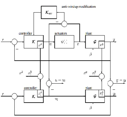
Anti-Windup
An anti-windup compensator consists of a nominal (most often linear) controller appended with anti-windup compensation. An important property of anti-windup compensation is that it leaves the loop unaffected as long as saturation does not occur. Consequently, the control action provided by the anti-windup compensator is identical to that of the nominal controller, as long as the control signals operate within the saturation limits. The design can be split into two parts where the rest part concerns the linear controller and the second the anti-windup modification .
Anti-windup was originally used for
© 2015, IRJET.NET- All Rights Reserved
Page 1338
Fig -2: Anti-windup2.2.1 Anti-Windup PID, PI Controllers In Direct
Torque Control
The windup phenomenon appears and results in performance degradation when the proportional-integral-derivative (PID) controller output is saturated. Integral windup is analyzed on the PI plane, and a new anti-windup PID controller is proposed to improve control performance of variable-speed motor drives and is experimentally applied to the speed control of a vector controlled induction motor driven by a pulse width-modulated voltage source inverter. The steady-state value of the integral steady-state is predicted while the PID controller output is saturated, and this value is utilized as an initial value of the integral state when the PID controller begins to operate in a linear range. Simulation and experiments result in more similar speed responses against load conditions and step reference change over conventional anti-windup schemes. Control performance, such as overshoot and settling time, is very similar to that determined by PID gain in the linear range.
Hence it becomes necessary to employ anti-windup strategy to prevent the controller from going into deep saturation and to check windup or rollover of controller output. Anti-windup schemes for PI controller are a well researched topic though newer and innovative methods are still coming up. Several such schemes for PID controllers utilizing limited or conditional integration method and tracking anti-windup method.
2.2.2Anti-windup PI control
Transfer function of a PI controller is expressed as GPI (s)
= Kp +Ki/s Here Kp is the proportional constant and Ki is the integral constant. The output from controller y can be expressed as
y = Kpe + Ki *(e*e)dt (1)
Here e is the input error. Fig-3:Anti-Windup PI Control
2.3
Mathematical Modelling Of Induction Motor
Electrical system equations: vs = Rs is + 1=w0(dfs=dt) + wkM(pi=2)fs (2)vr = Rr ir + 1=w0(dfr=dt) + (wk wm)M(pi=2)fr (3)
where the variables i,v,and f are 2-dimensional space vectors; for instance is = [ids iqs] (4)
wk is the speed of the reference frame, wm the rotor speed, M(pi/2)represents a 90 degree space rotator namely M(pi/2) = [0 -1;1 0] (5)
The flux linkage current relations are: fds = Ls ids + Lm idr (6)
fdr = Lm ids + Lr idr(Daxis) (7)
Ls = Lm + Lsl; Lr = Lm + Lrl (8)
fqs = Ls iqs + Lm iqr (9)
fqr = Lm iqs + Lr iqr(Qaxis) (10)
Mechanical system equations: Te = 2H(dwm=dt) + Bm wm + Tl (11)
where Te=fs(cross)is= M(pi/2) fs (dot) iss = fds iqs-fqs ids= fs x iss = M(pi/2) fs =ir
fr=Lm(ir is)=Lm/Lrr(fr iss) = 1/Lm0 (fr x fs) Lm0 =Lm
c/(1-c)c=1 - Lm2/(Ls Lr).
2.4 Results and Discussions
[image:3.595.56.264.99.290.2]© 2015, IRJET.NET- All Rights Reserved
Page 1339
Fig -4: current with PI control [image:4.595.47.235.331.545.2]Fig-5: Current with Anti-windup PI control
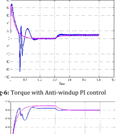
Fig-6: Torque with Anti-windup PI control
Fig-7: Speed with Anti-windup PI and PI control
3. CONCLUSIONS
The main reason for popularity of DTC is due to its simple structure, particularly when compared with eld-oriented control (FOC) scheme, which was introduced a decade earlier. The main advantages offered by DTC are decoupled control of torque and stator flux Excellent torque dynamics with minimal response time. Inherent motion-sensor less control method since the motor speed is not required to achieve the torque control. Absence of coordinate transform (required in FOC) Absence of voltage modulator as well as other controllers It is clear from the
DTC that decoupled control of stator flux and torque is possible From the overall it is clear that the DTC using the pi has torque ripples by using the anti-windup pi controller scheme the torque ripples can be reduced.
ACKNOWLEDGEMENT
First of all I thank Lord Almighty for the divine grace bestowed on me to complete this project successfully.
I would like to express my sincere gratitude to our institution, Adi Sankara Institute of Engineering and Technology, Kalady. I also thank our honorable Principal
Dr.N. Hariharan for providing us with all the facilities for making the project a success.
I am grateful to the Head of the Department Mrs.Krishnakumari.T for her constant encouragement and support.
I would like to extend my gratitude to my guides Mrs.Hima.T and Mrs Gomathy.S (Assistant Professors of EEE dept) for their inspiring assistance, support and timely advice and for her enterprising attitude that made my project successful.
Also I would like to thank our PGPP Sri. A.K.Divakara Menon for giving us innovative suggestions and assisting us in times of needs.
This acknowledgement will stand incomplete if my parents, friends and classmates are not thanked whose constant encouragement and timely criticism helped us to a great extent. They were instrumental in keeping my spirit high and their association with me will be always remembered.
REFERENCES
© 2015, IRJET.NET- All Rights Reserved
Page 1340
[2] P. Vas, Sensor less Vector and Direct Torque Control.Oxford, U.K. Oxford Univ. Press, 1998.
[3] T. Noguchi and I. Takahashi, “A new quick-response and high efficiency control strategy of an induction motor” IEEE Trans. Ind. Appl., vol.IA-22, no. 5, pp. 820827, Sep./Oct. 1986.
[4] D. Casadei, G. Serra, and A. Tani, “Improvement of direct torque control performance by using a discrete SVM technique” in Proc. IEEE 29thAnnual. PESC98, vol. 2, 1998, pp. 9971003.
[5] “Steady-state and transient performance evaluation of a DTC scheme in the low speed range” IEEE Trans. Power Electron, vol. 16,no. 6, pp. 846851, Nov. 2001. [6] Anti-windup Schemes for Proportional Integral and
Proportional Resonant Controller Anirban Ghoshal and Vinod John Department of Electrical Engineering, Indian Institute of Science, Bangalore Email: [email protected], [email protected] NA-TIONAL POWER ELECTRONIC CONFERENCE 2010 . [7] C. Lascu, I. Boldea, and F. Blaabjerg, “A modified direct
torque control for induction motor sensor less drive”
IEEE Trans. Ind. Appl, vol. 36,no. 1, pp. 122130, Jan./Feb. 2000.
[8] “An Optimized Switching Strategy for Quick Dynamic Torque Control in DTC-Hysteresis-Based Induction Machines” Auzani Jidin, Student Member, IEEE, Nik Rumzi Nik Idris, Senior Member, IEEE, Abdul Halim Mohamed Yatim, Senior Member, IEEE, Tole Sutikno, Student Member, IEEE, and Malik E. Elbuluk, Senior Member, IEEE.IEEE TRANSACTIONS ON INDUSTRIAL ELECTRONICS, VOL. 58, NO. 8, AUGUST 2011
[9] “Anti-Windup PID Controller With Integral State Predictor for Variable-Speed Motor Drives” HwiBeom Shin, Member, IEEE, and JongGyu Park IEEE TRANSACTIONS ON INDUSTRIAL ELECTRONICS, VOL. 59, NO. 3, MARCH 2012.
[10]“Low-Cost Direct Torque Control Algorithm for
Induction Motor Without AC Phase Current
Sensors”Brahim Metidji, Student Member, IEEE, Nabil Taib, Lot Baghli, Member, IEEE, Tou k Rekioua, and Seddik Bacha, Member, IEEE.IEEE TRANSAC-TIONS
ON POWER ELECTRONICS, VOL. 27, NO. 9,
SEPTEMBER 2012.
[11]J. Maes and J. A. Melkebeek, “Speed-sensor less direct torque control of induction motors using an adaptive flux observer, IEEE Trans. Ind Appl, vol. 36, no. 3, pp. 778785, May/Jun. 2000.
[12]N. R. N. Idris and A. H. M. Yatim, “Direct torque control of induction Machines with constant switching
frequency and reduced torque ripple” IEEE Trans. Ind. Electron., vol. 51, pp. 758767, Aug. 2004.
[13]Y.S. Lai and J.H. Chen, "A new approach to direct torque control of induction mo-tor drives for constant inverter switching frequency and torque ripple reduction,"IEEE Trans. on Energy Conversion, vol. 16, pp. 220-226, Sep. 2001.
[14]R. J. Wai, J. D. Lee, and K. L. Chuang, “Real-time PID control strategy for Maglev transportation system via particle Swarm optimization”, IEEE Trans. Ind. Electron., vol. 58, no. 2, pp. 629646, Feb. 2011. [15]B.Bahrani, S.Kenzelmann, and A.Rufer, “
Multivariable-PI-based d-q current control of voltage source converters with superior axes decoupling capability,”
IEEE Trans. Ind. Electron., vol. 58, no. 7, pp. 30163026, Jul. 2011.
BIOGRAPHIES
Saidas M.G was born on 11th
January 1991.He received his Bachelor Of Technology Degree In Electrical And Electronics from Cms College Of Engineering
Coimbatore cunder Anna
University 2013.He is currently pursuing Master Of Technology In Power Electronics And Power System At Adi Sankara Institute Of Engineering And Technology Kalady ,Ernakulam.His current research interests include electric drives control especially in direct torque control of induction motor using Sliding Mode And Anti-Windup PI Control.
Hima.T was born on 12th
may1986.She received B-Tech
Degree In Electrical and
Electronics from Adi Sankara Institute of Engineering And TechnologyKalady,Ernakulam.She
received M-Tech Degree In
Guidance And Navigational
Control from CET in 2010.He is
currently working as Asst