© 2016, IRJET | Impact Factor value: 4.45 | ISO 9001:2008 Certified Journal
| Page 1332
Investigation of Geometrical Parameter on Performance of Muffler Using
CFD Analysis
Krunal C. Chaudhari
1, Prof. R.Y.Patil
2, Prof. N.R.Suryawanshi
3, Prof. S.J.Chaudhari
41
PG Scholar Mechanical Engineering, SGDCOE, Jalgaon
2Guide & Head of Mechanical Engineering Dept., SGDCOE, Jalgaon
3
Asst.Prof. Automobile Engineering Dept., SGDCOE, Jalgaon
4Head of Automobile Engineering Dept., SGDCOE, Jalgaon
---Abstract
: Internal combustion engines are typically equipped with an exhaust muffler to suppress the acoustic pulse generated by the combustion process. A high intensity pressure wave generated by combustion in the engine cylinder propagates along the exhaust pipe and radiates from the exhaust pipe termination. Exhaust mufflers are designed to reduce sound levels at certain frequencies. New regulations and standards for noise emission increasingly compel the automotive firms to make some improvements about decreasing the engine noise. On the other hand, developments on automobile technology and increasing competition between manufacturers necessitates having being reduced weight, having capability of higher sound absorption and lower back pressure mufflers. Lightness could be possible if the thickness is decreased or the volume is reduced. However, this causes high back pressure. Therefore, the optimum design requires. Recently finite element methods are used to obtain flow characteristics and back pressure values of mufflers. Having used of this method, effect of different parameters can be examined without prototyping and best suitable muffler can be determined in the design process. Furthermore time and money can be saved.1.Introduction: Main Components Of The
Exhaust System
1.Exhaust manifolds 2.Catalytic converters 3.Mufflers
[image:1.612.318.577.247.437.2]4.Resonator 5.Tail Pipe
Fig 1 : Exhaust system in automobile
1.1. Muffler. :
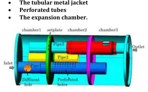
One of the components in the exhaust system of a vehicle is the muffler. Basically, the purpose of the muffler is to reduce the exhaust noise produced by the engine. The purpose of the muffler is to reduce the exhaust noise produced by the engine. Mufflers usually consist of: The tubular metal jacket
Perforated tubes
The expansion chamber.
[image:1.612.323.567.527.679.2]© 2016, IRJET | Impact Factor value: 4.45 | ISO 9001:2008 Certified Journal
| Page 1333
The basic constructions of muffler usually consist of thetubular metal jacket, perforated tubes and the expansion chamber. The arrangement of these components will guide the exhaust gas to flow from the inlet pipe of the muffler to the outlet (tail pipe). Inside the muffler, the noise from the exhaust gas will be reduced by dissipation of the wave energy, reflection of the wave energy towards the engine or the combination of the two. Today's vehicles are equipped with two types of muffler, either the reflective muffler which consists of a number of tubular elements of different transverse dimensions joined together so as to cause, at every junction, impedance mismatch and hence reflection of substantial part of the incident acoustic energy back to the source or the dissipative muffler which consist of ducts lined on the inside with acoustically absorptive materials. Both mufflers are having different construction, geometry, and principles in their application. The performance of a muffler is described by the Insertion loss, Transmission loss and Back pressure.
Insertion loss is defined as the difference between acoustic powers radiated without any filter and that with filter.
Transmission loss is a measure of the difference between the sound power incident (in decibel) at the entry to the muffler to that transmitted by the muffler. Transmission loss is independent of the source and presumes (or required) an anechoic termination at the downstream end.
Back pressure is the extra static pressure exerted by the muffler on the engine through restrictions in the flow of exhaust gases. An exhaust muffler is an acoustic filter except that wave’s are convicted downstream by the moving medium. Inside a muffler, it contains a deceptively simple set of tubes (not in all cases) with some holes in them. These tubes and chambers are actually designed to reflect the sound waves produced by the engine in such a way that they partially cancel themselves out. Most conventional mufflers are round or oval-shaped with an inlet and outlet pipe. Some mufflers contain partitions to help reduce engine noise. Generally an exhaust muffler should satisfy some basic requirements such as adequate insertion loss, low back pressure, ideal muffler sizing which couldaffect the cost and accommodation and the last one could be the durability to withstand rough conditions and extremely high temperatures. Hence some design considerations have to be taken in order to come up with an optimum muffler design. The parameters that govern the performance of the muffler are the muffler chamber design, restrictions of the flow of the exhaust gasses and the material of the muffler itself. The relationship between the noise and the back pressure is inversely proportional; lowering the noise level at the tip will result in high back pressure. However, thisrelationship is undesirable as the requirement is to have a quiet muffler with a small back pressure. The higher the
back pressure created by the exhaust system, the less is the net power available on the crankshaft and hence the more is the specific fuel consumption.
Vehicle engines generate noise because of the pressure wave created during the (sudden) opening of the exhaust valves of the engine. The noise is unwanted. Because exhaust noise must meet legislation targets, customer expectations and cost reduction which call for design optimization of the exhaust systems in the design phase. One of the components in the exhaust system of a vehicle is the muffler.
The arrangement of these components will guide the exhaust gas to flow from the inlet pipe of the muffler to the outlet (tail pipe) inside the muffler; the sound/noise energy is absorbed by muffler linig, or reflected back to the engine before the gas flows out to the atmosphere. The noise cancellation will reduce the noise that radiated by the vehicle to the surrounding.
The noise from the exhaust system consists of three components :
1. Pulsation noise
2. Flow generated noise coming from the orifice of the muffler outlet
3. Shell noise coming from the shell of the muffler. Shell noise may be limited by using a stiffer or damped shell, while flow generated noise. Such as turbulence and vortex shedding may be limited by minimizing geometrical discontinuities (edges, sharp bends etc).
© 2016, IRJET | Impact Factor value: 4.45 | ISO 9001:2008 Certified Journal
| Page 1334
1.2 Different Types Of Muffler
1.2.1. Reactive muffler :In this type of muffler Inlet and outlet tube are extended in chambers. Reactive mufflers generally consist of several pipe segments that interconnect with a number of larger chambers. The noise reduction mechanism of reactive silencer is that the area discontinuity provides an impedance mismatch for the sound wave travelling along the pipe. This impedance mismatch results in a reflection of part of the sound wave back toward the source or back and forth among the chambers. The reflective effect of the silencer chambers and piping (typically referred to asresonators) essentially prevents some sound wave elements from being transmitted past the silencer. The reactive silencers are more effective at lower frequencies than at high frequencies, and are most widely used to attenuate the exhaust noise of internal combustion engines.
1.2.2.Absorptive muffler :This type of muffler design uses only absorption of the sound wave to reduce the noise level without messing with the exhaust gas pressure. Ti is known as glass pack muffler and it reduces backpressure but producing higher noise. The sound produced by this type of muffler is much higher compared to the other type of mufflers.
1.2.3. Combination muffler : Some silencers combine both reactive and absorptive elements to extend the noise attenuation performance over a broader noise spectrum. Combination silencers are also widely used to reduce engine exhaust noise
1.3. Problem Statement:
There is an increasing awareness of noise pollution on the part of the general public in urban areas, especially noise caused by automotive. A pollutant of concern to the mankind is the exhaust noise in the internal combustion engine. However this noise can be reduced sufficiently by means of a well designed muffler. The suitable design and development will help to reduce the noise level, but at the same time the performance of the engine should not be hampered by the back pressure caused by the Muffler. In particular, users of certain types of general automotive may be compelled to restrict operations and/or modify their automotive to comply with existing or forthcoming noise legislation that will specify upper limits on external noise levels. Analysis of this noise indicated that engine-exhaust noise was the primary cause of both unacceptably high cabin-noise levels and radiated far-field cabin-noise.2. BASIC REQUIREMENT OF MUFFLER
DESIGN
2.1 General Requirements
Quiet
Simple maintenance
Performance
Compact design
Light weight
2.2. Specific Requirement
Reduce the sound emissions
Replaceable
Doesn’t increase backpressure
Easy mounting
Within the budget
Easy manufacturing
2.3 Functional Requirements Of A Muffler
.:There are numerous functional requirements that should be considered when designing a muffler for a specific application. Such functional requirements may include adequate insertion loss, backpressure, size, durability, desired sound, cost, shape and style. These functional requirements are detailed below focusing on an automotive muffler’s functional requirements
Adequate Insertion Loss: The main functional of a muffler is to “muffle” or attenuate sound. An effective muffler will reduce the sound pressure of the noise source to the required level
Backpressure: Backpressure represents the
extra static pressure exerted by the muffler on the engine through the restriction in flow of exhaust gasses. Generally the better a muffler is at attenuating sound the more backpressure is generated.
Size :The available space has a great influence on the size and therefore type of a muffler that may be used. A muffler may have its geometry designed for optimum attenuation however if it does not meet the space constraints, it is useless.
© 2016, IRJET | Impact Factor value: 4.45 | ISO 9001:2008 Certified Journal
| Page 1335
Aluminized vs. stainless are two types of steel commonly used to manufacture muffler. Stainless steel mufflers are considered more durable and can last up to 10 years. Aluminized mild steel mufflers are prone to corrosion, and therefore they typically last around 4 years.
Desired sound: There has however been a
growing trend in Australia in recent years for young drivers wanting to “hot up” their vehicles and this includes muffler modification. Muffler modification of a stock vehicle is generally done for two reasons being performance and sound.
Cost: A major factor in any component is the cost to the consumer. Silencers not only have to be effective in performing their task they need to be affordable otherwise the product will fail in the marketplace. Aftermarket car exhaust mufflers vary in price from $90 to $700. The cost is dependent on the materials used in the construction of the muffler, design integrity, durability and labor costs.
Shape and Style: Automotive mufflers come in all different shapes, styles and sizes depending on the desired application. Generally automotive mufflers consist of an inlet and outlet tube separated by a larger chamber that is oval or round in geometry. The inside detail of this larger chamber may be one of numerous constructions.
3. INPUT PARAMETER:
Case Study – LCV Diesel engine vehicle (Ciaz)
Engine Data: Bore (D) = 69.6 mm Stroke (L) = 82 mm No. Cylinders (n) = 4
Engine power (P) = 88.7 bhp at 4000 RPM
Muffler Volume Calculations: Swept volume per cylinder = 0.25 (3.14 x 69.6 2 x 82) (Vs) = 0.3119
lit. Total swept volume in liters = 4x0.3119= 1.247 Lit. Volume to be considered for calculation = 0.5 x Vs x n= 0.6239 Lit
Silencer volume: Volume of silencer must be at least 12 to 25 times the volume considered. Volume can be adjusted depending on the space constraint.
Factor considered is = 22
Silencer volume = factor x consider volume = 13.73 Lit Diameter of Muffler Calculations: Vm = 0.25x
0.01373 = 0.25x π x d 2 x 0.5
d = 0.187 m= 187 mm
Diameter of Pipe Calculations:
As per the standards of the supercritical grade of mufflers, the diameter of the body should be about three times than the exhaust pipe diameter.
d = 3* d exhaust 187= 3* d exhaust d exhaust = 62.33 mm
Material properties.
Density : 7900 kg/m3 Specific heat : 500 J/(kg*K)
Thermal Conductivity : 16.2 W/(m*K) Conductivity type: Isotropic
Initial values for velocity inlet as the inlet boundary condition.
Area : 0.003051 (m2) Temperature: 470 (K) Viscosity: 2.7e-05 (kg/ms) Enthalpy: 749575.3 (J/kg) Density: 0.696 (kg/m3) Length: 500(mm) Velocity: 80 (m/s) Ratio of specific heats : 1.4
3.1.Dimensional data. (base case)
© 2016, IRJET | Impact Factor value: 4.45 | ISO 9001:2008 Certified Journal
| Page 1336
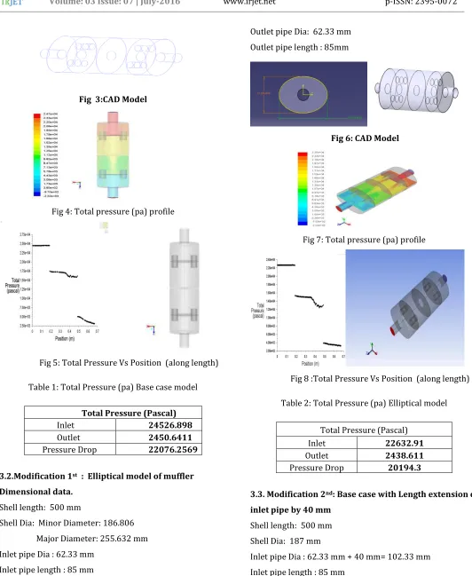
Fig 3:CAD Model
Fig 4: Total pressure (pa) profile
[image:5.612.37.569.70.719.2]Fig 5: Total Pressure Vs Position (along length)
Table 1: Total Pressure (pa) Base case model
Total Pressure (Pascal)
Inlet 24526.898
Outlet 2450.6411
Pressure Drop 22076.2569
3.2.Modification 1st : Elliptical model of muffler
Dimensional data.
Shell length: 500 mm
Shell Dia: Minor Diameter: 186.806 Major Diameter: 255.632 mm Inlet pipe Dia : 62.33 mm
Inlet pipe length : 85 mm
Outlet pipe Dia: 62.33 mm Outlet pipe length : 85mm
[image:5.612.310.560.77.497.2]Fig 6: CAD Model
Fig 7: Total pressure (pa) profile
[image:5.612.67.264.527.584.2]Fig 8 :Total Pressure Vs Position (along length)
Table 2: Total Pressure (pa) Elliptical model
Total Pressure (Pascal)
Inlet 22632.91
Outlet 2438.611
Pressure Drop 20194.3
3.3. Modification 2nd: Base case with Length extension of
inlet pipe by 40 mm
Shell length: 500 mm Shell Dia: 187 mm
[image:5.612.347.547.545.603.2]© 2016, IRJET | Impact Factor value: 4.45 | ISO 9001:2008 Certified Journal
| Page 1337
Outlet pipe Dia: 62.33 mm [image:6.612.40.289.109.500.2]Outlet pipe length : 85mm
Fig 9: CAD Model
Fig 10: Total pressure (pa) profile
Fig 11: Total Pressure Vs Position (along length)
Table 3: Total Pressure (pa) Base case with Length extension of inlet pipe by 40 mm
Total Pressure (Pascal)
Inlet 24470.32
Outlet 2296.46
Pressure Drop 22173.86
4. Conclusion
If vehicles did not have a muffler there would be an unbearable amount of engine exhaust noise in our environment. Noise is defined us unwanted sound.
All noise emitted by an automobile doesn’t come from the exhaust system. Other contributors to vehicle noise emission include intake noise, mechanical noise and vibration induced noise from the engine body and transmission.
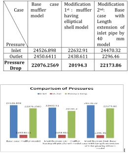
Table 4: Total Pressure (pa)
Case
Pressure
Base case muffler model
Modification 1st : muffler
having elliptical shell model
Modification 2nd: Base
case with Length extension of inlet pipe by
40 mm
model Inlet 24526.898 22632.91 24470.32 Outlet 2450.6411 2438.611 2296.46
Pressure
Drop 22076.2569 20194.3 22173.86
[image:6.612.319.579.233.545.2]© 2016, IRJET | Impact Factor value: 4.45 | ISO 9001:2008 Certified Journal
| Page 1338
1. Exhaust pressure reduction in base case model is90.008%
2. Exhaust pressure reduction in elliptical shell model is 89.22%
3. Exhaust pressure reduction in base case with Length extension of inlet pipe by 40 mm model is 90.615%
Hence we conclude that base case with Length extension of inlet pipe by 40 mm model is more efficient in reducing the exhaust pressure when compared to model base case model and elliptical shell model.
REFERENCES
[1]. Min-Chie Chiu Long-JyiYeh, Ying-Chun Chang, Tian-SyungLan “Shape Optimization of Single-Chamber Mufflers with Side Inlet/Outlet by Using Boundary Element Method, Mathematic Gradient Method and Genetic Algorithm”TamkangJournal of Science and Engineering, Vol. 12, No. 1, pp. 8598 (2009)
[2]. S. N.Y. Gergesand R. Jordan “Muffler Modeling by Transfer Matrix Method and Experimental Verification”Federal Univ. of Santa CaterinaMechanical Engineering Dept CP 476 Florianópolis, Brazil
[3]. SudarshanDilipPangavhane ;AmolBhimraoUbale ; Vikram A Tandon ; Dilip R Pangavhane “Experimental and CFD Analysis of a Perforated Inner Pipe Muffler for the Prediction of Backpressure”SudarshanDilipPangavhane et.al / International Journal of Engineering and Technology (IJET)