2018 International Conference on Computer, Communications and Mechatronics Engineering (CCME 2018) ISBN: 978-1-60595-611-4
Research on Improvement of the End Cover of Intra-vane Type Pump
Based on ANSYS
Shao-nian LI
1, Hui WANG
2,*, Guo-lei SI
3, Kai LIN
1and Yang-yang LIU
11College of Energy and Power Engineering, Lanzhou University of Technology, Lanzhou, China
2School of Mechanical and Electrical Engineering, Lanzhou Institute of Technology, Lanzhou, China
3Sichuan Aerospace Fenghuo Serve Control Technology Co., Ltd., Chengdu, China
*Corresponding author
Keywords:Intra-vane type pump, Distribution side plate (FDSP), Deformation, End cover.
Abstract. The flow distribution side plate (FDSP) of the intra-vane pump is loaded to the hydraulic thrust of the oil film of the distribution pair and the hydraulic pressing force of the kidney-shaped cavity on the end cover of the pump core. The kidney-shaped cavity structure in the end cover has a certain effect on the deformation of the FDSP, and then affects the oil film thickness, leakage power loss and friction power loss of the distribution pair. In this paper, the hydraulic pressure distribution of oil film in the distribution pair is studied. Using the principle of redundant squeezing force, the calculation formula for the kidney-shaped cavity area on the end cover is deduced. Through simulation, the contour of the deformation of the FDSP is obtained, and it is found that the deformation of the discharge area and the oil suction area is not uniform. By improving the design of the kidney-shaped cavity structure in the end cover, the uniformity of the FDSP deformation can be achieved. The research conclusion has certain guiding significance for improving the volume efficiency and mechanical efficiency of the intra-vane type pump.
Introduction
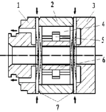
[image:1.595.242.351.574.689.2]The intra-vane type pump has the advantages of high pressure, small volume, stable operation, low noise and long service life. It is widely used in pressure die-casting machinery, engineering machinery and various hydraulic systems [1]. The pump core is mainly composed of front and back cover, cam ring, rotor, FDSP, shaft and vanes, and the structure is shown in Figure 1. The FDSP structure capable of flexing deformation is a unique structure of the vane pump, and the clearance between the rotor and the FDSP is automatically compensated, so that the volumetric efficiency and the working pressure of the pump under the oil film lubrication condition are significantly improved [2].
Figure 1. Schematic diagram of the pump core inside the intra-vane type pump.
[image:2.595.182.415.69.189.2]
(a) (b)
Figure 2. Schematic diagram of the FDSP of the intra-vane type pump.
(a) Front side of the FDSP; (b) Back side of the FDSP
However, the deformation of the FDSP will cause the change of the film thickness of the floating distribution pair, which has an important influence on the oil leakage power loss and the oil viscous friction power loss [3]. In this paper, the deformation simulation of the FDSP of the intra-vane type pump and the influence of the kidney cavity structure of the front and back end cover to the deformation of the FDSP are studied. A new structural design for end cover is proposed and the research results can help to control the shape of the film in floating distribution pair to improve the volumetric efficiency and mechanical efficiency of the intra-vane type pump.
Area Calculation of the Kidney-shaped Cavity of the End Cover
The FDSP is subjected to the hydraulic thrust of the distribution pair from the front side and the hydraulic pressing force of the oil in the kidney-shaped cavity on the end cover from the back side. The FDSP is deformed under the action of two forces. The structure of FDSP is shown in Figure 2. The kidney-shaped cavity on the end cover is connected with the oil discharge port, and the oil pressure is the same as the oil pressure in the oil discharge port, and the hydraulic pressuring force of the kidney-shaped cavity on the back side is the product of the pressure of the oil discharge port and the area of the kidney-shaped cavity.
[image:2.595.228.365.529.634.2]According to the structural characteristics of the oil film, a two-dimensional model of the oil film is constructed. The oil discharge pressure is applied on the boundary line of the oil discharge port and the intra-vane oil distribution groove, and the oil suction pressure is set on the boundary line of the oil suction port, the oil suction port conduction cavity and the clearance between the shaft and the FDSP. The contour of oil film pressure can be obtained as shown in Figure 3.
[image:2.595.229.369.662.769.2]Figure 3 shows the pressure of oil film in the flow distribution pair is mainly distributed in the discharge area and it is approaching zero in the suction area. The film pressure from the inner radius of the discharge port to the inner radius of the oil distribution groove of the intra-vane cavity is equal to discharge pressure, and decrease gradually to zero in the discharge area gradually from the inner radius of the oil distribution groove to the radius of shaft hole.
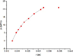
Figure 4 shows the distribution of the oil film pressure along the radial direction in the discharge area of the flow distribution pair. It can be seen that the oil film pressure from the clearance between the shaft and the FDSP to the oil distribution groove of the intra-vane cavity increases as a logarithmic function in the flow distribution pair of the intra-vane pump. And formula for calculating the pressure of oil film as follow.
s h P R R R r P ) ln( ) ln( 1 2 1
(1)
Where r is distribution pair radius (m), R1 is the radius of the clearance between the shaft and the
FDSP (m), R2 is the radius of the oil distribution groove of the intra-vane cavity (m), Ps is oil
discharge pressure (Pa).
The hydraulic thrust of the distribution pair to the distribution side plate is the area integral of the distribution pressure, and calculation formula as follow.
] ) ln( 2 [ 1 2 2 1 2 2 2 3 R R R R R P
Ft s (2)
Where is distribution angle of discharge area (rad), R3 is outside radius of distribution pair( m).
The design method of residual pressing force is usually adopted for the FDSP. The hydraulic pressing force of the oil in kidney-shaped cavity on the FDSP is slightly larger than the hydraulic thrust of the distribution pair on the FDSP. In addition, the hydraulic pressing force of kidney cavity is provided by the oil in the oil discharge port. So the area of kidney-shaped cavity of the end cover can be obtained as follows:
] ) ln( 2 [ 1 2 2 1 2 2 2 3 R R R R R P F P F A s t s
y
(3)
Where is compaction coefficient, A is the area of the kidney-shaped cavity (m2).
Deformation Simulation of FDSP
The FDSP is a peripheral fixed support ring plate with machined surface and partially cut away. The structure and stress is complex, the theoretical calculation is difficult too. In this paper, the deformation of the FDSP is simulated by ANSYS software. Here a three-dimensional model for FDSP is created and the unstructured grid is used to create a finite element model. The FDSP is loaded with hydraulic thrust, hydraulic pressing force and related constraints [4].
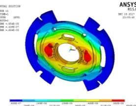
Figure 5. Simulation diagram of FDSP deformation of intra-vane pump at 21MPa.
It can be seen from figure 5, the deformation is mainly concentrated in the discharge area and relatively small in the suction area. The maximum value of the deformation of the FDSP is near the inner radius of the kidney-shaped cavity in the discharge area.
The uneven deformation distribution of the distribution side plate will affect the uniformity of the oil film thickness of the distribution pair. If the deformation is large in the discharge area, the oil film thickness will be small which will accelerate wear and affect the service life of the FDSP. If the deformation in the oil suction region is small, the oil film thickness will be large which will cause oil leakage in distribution pair and increase oil leakage power loss.
Improvement and Analysis for Structure of End Cover
In order to solve the above-mentioned problem of uneven deformation of the FDSP, the structure of the end cover was studied. The hydraulic thrust of the flow distribution pair on the FDSP is not easy to change due to the structure restriction. The hydraulic pressing force of the kidney-shaped cavity of the end cover on the flow distribution side plate is determined by the size and shape of the kidney-shaped cavity in the end cover, and the deformation of the FDSP can be homogenized by studying the kidney-shaped cavity of the pump core cover. According to formula (3), the area of kidney-shaped cavity of the end cover can be calculated. In the premise of keeping the area of the kidney-shaped cavity unchanged to study and improves the structure of the kidney-shaped cavity of the end cover[5].
On the basis of the shape of kidney-shaped cavity, this paper proposes circular groove structure model, fan-shaped + pressure groove structure model and kidney-shaped cavity + pressure groove structure model. Three kinds’ specific structures of end cover are shown in figure 6.
(a) (b) (c) (d)
Figure 6. Original structure and improved structure of end cover.
(a) Original structure model; (b) Circular groove structure model; (c) Fan-shaped + pressure guide groove structure model; (d) Kidney-shaped cavity + pressure groove structure model.
[image:4.595.110.519.522.625.2](a) (b) (c)
Figure 7. Contour of deformation of FDSP using improved structure of end cover.
(a) Using circular groove structure model; (b) Using fan-shaped cavity + pressure guide groove structure model; (c) Using the kidney-shaped cavity + pressure groove structure model.
It can be obtained the conclusions as follow from figure 7, compared with the deformation simulation diagram using the original structure end cover in figure 5. When using the circular groove structure model for end cover in figure 6 (b), the deformation is too large in the suction area on the FDSP and is insufficient to obtain the uniform deformation. When the fan-shaped + pressure structure model is used as showed in figure 6(c), the deformation of the FDSP is too large in discharge area, and is insufficient in the suction area, and it cannot be homogenized. When the kidney-shaped cavity + pressure groove structure model is used as shown in figure 6(d), the deformation of the FDSP is regular and uniform, which can eliminate the problem of inconsistent deformation in the oil suction area and discharge area. Therefore, the kidney-shaped cavity + pressure groove structure model is the most ideal structure model for the end cover.
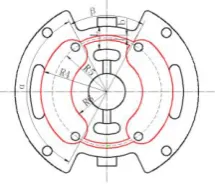
Figure 8. Main parameters of end cover with kidney cavity + pressure groove structure
However, it can be seen from figure 7 (c) that the kidney-shaped cavity + pressure groove structure model causes the maximum deformation of the FDSP is quite different from the deformation value caused by the original structure model, so it is necessary to modify the structure model. The method is mainly carried out from three aspects: the size of the inner radius of the kidney-shaped cavity, the width of the pressure groove, and the position of the center line of the pressure groove, and its parameters are marked as shown in figure 8.
In order to ensure the volumetric efficiency of the pump is the same as that of the original pump, the maximum deformation of before and after improvement of the FDSP must be close. Therefore, as long as two parameters affecting the bending distance of the distribution side plate are determined, the third parameter can be determined by deformation simulation.
(1) Determination of the width of the pressure groove. The kidney-shaped cavity pressure groove is located between the oil distribution groove at the bottom of the mother vane and the oil suction port. Sealing rings must be installed on both sides of the pressure guide groove to prevent hydraulic oil leakage, so the width of the pressure guide groove is set as follow.
) ' 2 ( 3 1
b L
b (4)
[image:5.595.242.350.382.474.2](2) Determination of the position of the pressure groove. The position of the pressure groove is taken on the middle circle between the oil distribution groove and the oil suction port at the bottom of the mother vane, and the radius of the circle is R5.
[image:6.595.64.536.294.423.2](3) Determination of inner radius of kidney-shaped cavity. According to the maximum deformation of the FDSP is unchanged before and after improvement of end cover, the inner radius of the kidney-shaped cavity is determined by deformation simulation. The actual parameters of the pump used in the simulation are shown in Table 1.
Table 1. Parameters of intra-vane type pump.
Parameter value
Distance between oil distribution groove and oil suction port at bottom of intra-vane(L)
0.012 m
Outside radius of kidney cavity(R4) 0.0345 m
Angle of fan-shaped region of kidney cavit() 1.639rad Sealing ring width(b') 0.002 m Middle circle radius(R) 0.0285m Angle of pressure groove(β) 0.907rad
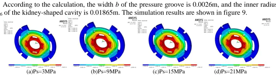
According to the calculation, the width b of the pressure groove is 0.0026m, and the inner radius R6 of the kidney-shaped cavity is 0.01865m. The simulation results are shown in figure 9.
(a)Ps=3MPa (b)Ps=9MPa (c)Ps=15MPa (d)Ps=21MPa
Figure 9. Simulation diagram of deformation of FDSP using improved end cover.
It can be seen from figure 9, the deformation of the FDSP is distributed regularly and evenly in both the oil suction area and the oil discharge area under various load pressure conditions, and the maximum deformation is close to the FDSP using the original kidney-shaped cavity, which can reduce the wear of the rotor on the FDSP and reduce the leakage of the flow distribution pair in suction area.
The maximum deformation of the FDSP using the before and after improvement end cover is calculated, and it is found the relative error of them is less than 2% when pump working in different pressures, which is within a reasonable range, indicating that the improvement of the pump core cover of the intra-vane pump is scientific and reasonable.
Conclusion
Through the above improvement study on the end cover of the intra-vane pump, the conclusions are obtained as follows:
(1) The oil film pressure of the distribution pair of the intra-vane pump is mainly distributed in the oil discharge area, and the oil suction area pressure approaches zero. The oil film pressure in the oil discharge area from the oil distribution groove of the intra-vane cavity to the shaft decreases to zero as a logarithmic function.
(2) The distribution side plate of the intra-vane pump is deformed toward the rotor, and the deformation is mainly concentrated in the oil discharge area, while the oil suction area is relatively small.
(4) Machining the pressure groove on the middle line of the oil distribution groove and the oil suction port at the bottom of the mother vane in the suction area of the end cover, and reforming the outer radius of the kidney-shaped cavity to be the same as the distribution pair can make the FDSP of the intra-vane pump deform uniformly, reduce the wear of the rotor on the FDSP in the oil discharge area, and reduce the leakage of the distribution pair in the oil suction area at the same time.
Acknowledgement
This research was financially supported by the National Natural Science Fund (51565026).
References
[1] Ma Wen-cheng. The present situation and Prospect of High Pressure Vane Pump. Fluid Power Transmission and Control [J], 2006, (6), pp. 1-6.
[2] JI Hong. Hydraulic & Pneumatic Transmission and Control [M].Wuhan: Huazhong University of Science and Technology Press, 2009.
[3] Zhang Tian-yu, Zhang Hao. Failure Mechanism for High- pressure Vane Pump of Loader. Chinese Hydraulics & Pneumatics [J]. 2015, (06), pp. 104 -107+111.
[4] Zhao Yong-fu, Xu jia-yin, Wang Hai-ling. Temperature Influence Analysis on Distribution Plate of an Axial Piston Pump Based on ANSYS Workbench. Construction Machinery and Equipment[J]. 2013, (44), pp. 9-12.