2018 3rd International Conference on Information Technology and Industrial Automation (ICITIA 2018) ISBN: 978-1-60595-607-7
Application Research of Microwave Detection
Technology in Smart Home System
Baoqing Deng, Yuchuan Jia, Shaoqun Zeng, Shaohua Yang,
Qiping Li and Zhongbo Yang
ABSTRACT
Microwaves have better environmental adaptability, and their detection accuracy is much higher than infrared detection, and the system is much simpler than laser. Electromagnetic waves (especially microwaves) have a Doppler effect and have better accuracy for the measurement of moving objects. In this paper, a microwave-friendly penetrability and Doppler Effect principle is used to design and develop a
device for concealed alarms for smart home anti-intrusion systems.1
INTRODUCTION
With the rapid development of the Internet and Internet of Things technologies, smart home systems are getting more and more attention. The smart home system also provides a comfortable home environment, providing convenience for people's lives, building efficient management systems for residential facilities and family schedules, improving home safety, convenience and comfort, and achieving environmental protection and energy conservation [1-3]. The research on the anti-theft and anti-intrusion of smart home systems has gradually attracted the attention of the industry. Some commonly used ranging methods, such as ultrasonic ranging, laser ranging, traveling wave fault location and camera system ranging, have achieved remarkable results in targeted qualitative measurements [4]. The good penetration of microwaves into common building materials such as plastics, ceramics, and glass and brick walls provides an inherent advantage for the hidden
1
Baoqing Deng, Yuchuan Jia, Zhuhai College of Jilin University, Guangdong, China Shaoqun Zeng, Zhuhai Yantai Electronic Technology Co., Ltd, Guangdong, China
arrangement of microwave sensors. In particular, the Doppler effect of microwaves provides a wide range of applications for moving object measurements. In the smart home system for the anti-theft system, as well as some factories in high-pressure areas or dark areas where the ground is dangerous, and prohibiting the entry of unrelated people, it is necessary to monitor the moving targets.
MICROWAVE DOPPLER EFFECT
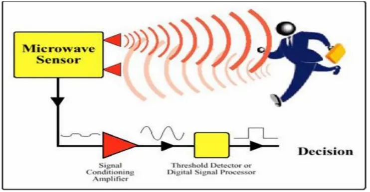
The Doppler theory is based on time, when a radio wave (especially microwave) hits an object during travel, and the wave is reflected. The frequency of the reflected wave changes as the object moves [5]. The faster the moving object moves, the more obvious the Doppler Effect. If the position of the object is fixed, the frequency of the reflected wave should be equal to the frequency of the emission wave; if the object moves in the direction of the emission, the reflected wave will be compressed, that is, the frequency of the reflected wave will increase. Conversely, the frequency of the reflected wave is reduced [6]. Microwave sensor diagram shown in Figure 1.
[image:2.612.112.483.448.641.2]The microwave intrusion detector performs non-contact detection and prevention in the three-dimensional space, and can cover the radiation angle range of 600-700, which is less affected by the climatic conditions [7]. The microwave intrusion detector is generally an X-band microwave with a frequency of 10.525 GHz. When there is relative motion between the source and the detected object, according to the Doppler effect of the microwave and the frequency shift of the echo generated by the moving target, the Doppler shift can be measured to know the characteristics of the target (size, speed, quantity, Direction) information.
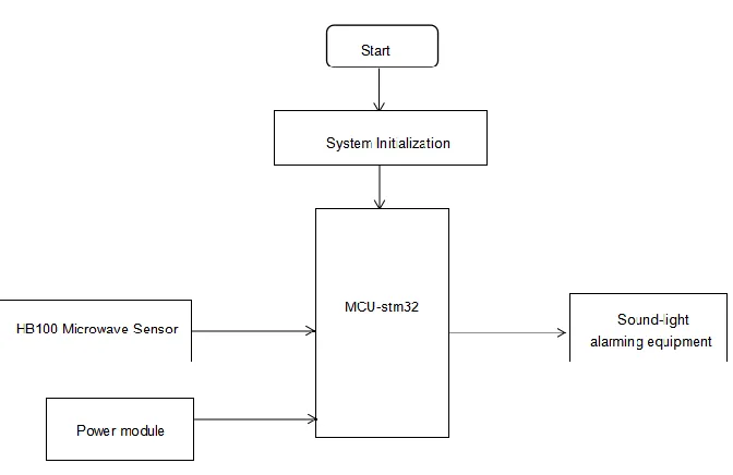
Figure 2. System diagram.
SYSTEM HARDWARE DESIGN
In view of the diversity of smart home use scenarios, it is not suitable for the detection of human body or other objects to use infrared detection that requires window opening, and laser detection cannot be used. Therefore, a microwave detection and alarm device is designed.
System Block Diagram
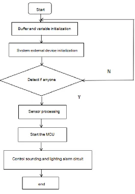
MCU-STM32 is designed as control center. The system is divided into the host part and the slave part. The host part is the MCU to control the sounding and lighting alarm circuit, and the slave part is composed of the microwave sensor. First, the human body intrusion is detected by the microwave sensor HB100, and the emission source and the detected object occurred the relative motion. The frequency shift of the reflected signal and the emission signal is collected. The microwave sensor outputs a square wave to the medium fracture of the MCU. The MCU detects the square wave. When someone invades, the square wave frequency changes and the MCU controls the sounding and lighting alarm circuit to alarm. The system diagram is shown in Figure 2.
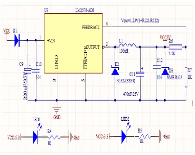
Power Module
ripple. D3 is a diode that can steady the output voltage to protect the capacitor. The LM2576-ADJ regulates the external input voltage to 5V for the entire circuit to operate. LED1 and LED2 are system power indicating lamps.
Microwave Induction Module
[image:4.612.117.498.323.626.2]This experiment uses the HB100 microwave mobile sensor, which is an X-band microwave sensor that uses the Doppler phenomenon to sense motion. It consists of FET medium DRO microwave concussion source (10.525 GHz), power divider, transmitting antenna, receiving antenna, mixer, geophone and other circuits. The sensor emits the low frequency and receives the energy reflected back from the object [8]. Once the motion of the object is detected by it, the emission frequency is replaced by the reflective microwave frequency, and the alternate microwave is mixed with the emission microwave, resulting in a low-frequency voltage being output from the sensor [9-10]. Microwave sensor diagram shown in Figure 3. The peripheral circuit of HB100 is shown in Figure 4.
Figure 4. The peripheral circuit of HB100.
The Doppler microwave sensor HB100 detects the waveform terminal IF, and after two operational amplifiers U1 and U2, the amplified signal is output by FREQ. The output terminal FREQ outputs a square wave and is connected to the interrupt port of MCU. MCU detects the square wave. When someone invades, the frequency of the square wave changes, and MCU controls the sounding and lighting alarm circuit to alarm.
Its parameters are as follows:
Emission: Transmitting frequency:10.525GHz Output power(Minimum):13dBm EIRP
Operating voltage:4.75V-5.25V
Detection range: 1-20M
Execution Circuit
LED DESIGN
SOUNDING AND LIGHTING ALARM CIRCUIT
[image:6.612.117.284.201.363.2]The alarm driving circuit is driven and controlled by the BEEP end of the MCU processor. The BEPU end of the MCU processor outputs a pulse signal, which is amplified by the transistor Q1 to drive the buzzer to make a sound. As shown in figure 6.
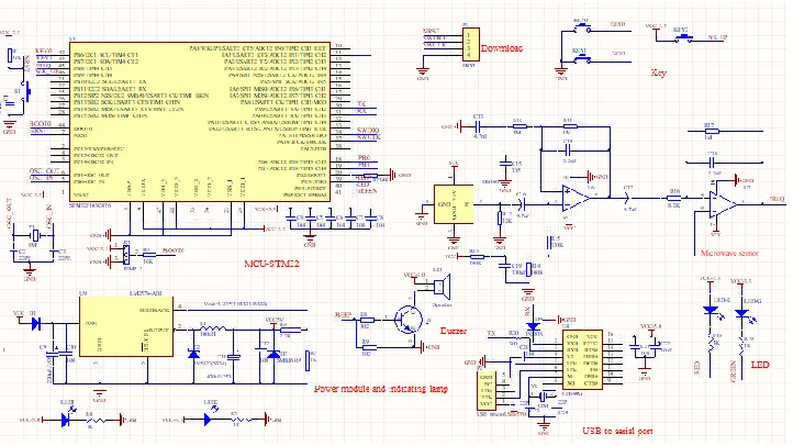
System principle integration shown in Figure 7.
Figure 5. LED circuit.
[image:6.612.322.501.206.351.2]Figure 7. System schematic.
[image:6.612.136.497.407.610.2]SOFTWARE PROGRAM IMPLEMENTATION
Main Program Design
[image:7.612.165.430.279.660.2]Interrupt Function Design
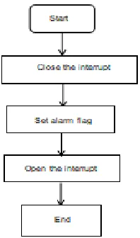
When someone invades, the sensor triggers an external interrupt. Enter the interrupt program, turn off the interrupt, and prevent the external interrupt from being triggered again during the alarm. Then set the alarm flag, open the interrupt, and return to the main program. As shown in figure 9 [13].
CONCLUSIONS
[image:8.612.247.346.393.561.2]According to the application of microwave technology in the residential system, a microwave anti-theft system with simple operation is designed. This paper is designed to be a low-cost, safe and reliable security product. The microwave sensor is selected from HB100, which is not affected by temperature, humidity, noise, airflow, etc. It has strong anti-radio interference capability and low output power, which will not cause harm to the human body. STM32 is selected as the main controller, featuring high performance, low cost and low energy consumption. At the same time, the main controller and the sounding and lighting alarm circuit in the system are connected together, which can quickly and effectively cooperate with the alarm.
Figure 9. Interrupt function flow chart.
ACKNOWLEDGEMENTS
REFERENCES
1. Y Wang. (2018). Status Quo of Smart Home Development and Suggestions for Future Development [J]. Telecommunications Network Technology(3).
2. Z M Li. (2018). Application of Internet of Things Technology in Smart Home Environment.
China Informatization (5).
3. W G Lu. (2018). Discussion on Artificial Intelligence Application in Computer Network Technology. Journal of Heihe University (4).
4. X Y Zhu. (2012). An Image Ranging Algorithm Based on Frequency Domain Analysis. Internet of Things (9), 16-18.
5. P F Liu, C Zhao, J Y Wang, & J Zhang. (2011). Research on Intelligent Video Surveillance System Based on Multi-sensor Information Fusion Technology. Electronic Test (4), 38-40. 6. G T Liu, & H Wei. (2013). Suggestions on the Development of Railway Safety Warning Devices
Using Doppler Radar and RFID Technology. Technology Entrepreneurs (12), 146-147.
7. J Y Liu, & Y Ren. (2015). Application and Installation of Common Intrusion Alarm Detection Systems. Automation and Instrumentation (4), 236-237.
8. N Yang. (2008). Wireless Monitoring and Alarm System Design. (Doctoral Dissertation,
Liaoning University of Engineering and Technology).
9. Z Wu, & Y Peng. (2011). Design of Transmission Line Bird Repellent Device Based on Single Chip Microcomputer. Western China Science and Technology, 10(17), 26-27.
10. J J Yao, J H Zhou, Y J Ren, & W Han. (2011). Application of Mobile Sensors in Wireless Video Surveillance Systems. Sensors and Microsystems, 30(3), 135-137.
11. L Q Wu. (2009). Embedded Video Surveillance System Based on Microwave Technology. (Doctoral Dissertation, Nanchang University).
12. J Y Zhang. (2002). Intermediate Course for Single - Chip Machines. Principles and Applications. Beijing: Beijing Airlines Air and Sky University Publishing House.