2019 International Conference on Information Technology, Electrical and Electronic Engineering (ITEEE 2019) ISBN: 978-1-60595-606-0
Edge Fusion Algorithm for Orthogonal Projection of Multiple
Overlapping Regions
Hui-bai WANG, Xin-qi WANG
*and Hong-qing SHI
North China University of Technology, Beijing, China
*Corresponding author
Keywords: Stereo projection, Overlapped projection, Edge blending.
Abstract. Stereo projection display technology has become a hot topic in recent years. A edge fusion technology for multiple projection images with multiple overlapping areas is proposed. An edge fusion method is proposed, which can be used for edge fusion of multiple overlapping areas in irregular fusion areas, eliminate the bright band caused by overlapping projection and realize multi-channel seamless Mosaic display. The practical application shows that this method can make the multi-projector display system with multiple planar and different shape and multiple overlapping areas project a seamless vision.
Introduction
In order to display super-large, panoramic and three-dimensional images and realize seamless splicing of multi-channel projection system[1-2], two problems must be solved: one is to carry out geometric correction of projected images[3], and the other is to fuse the edges of adjacent images[4].
In this paper, a new edge fusion method is proposed to adapt stereo images in real scenes[5]. This
edge fusion method maximizes the effective pixels of all projectors, and can support the Mosaic and display of multi-planar, irregular images and multi-overlapping multi-projector images.
Edge Fusion Algorithm for Orthogonal Projection
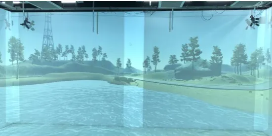
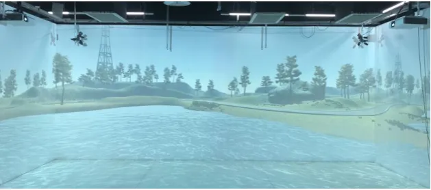
[image:1.595.160.436.588.726.2]The geometric correction step completes the correction of the image distortion and obtains the image without geometric distortion. The whole image is segmented into a stereoscopic projection of the left side, the front side and the right side. Adjacent projection planes with overlapping areas are called fusion zones. The pixels with overlapping parts of the fusion in the stereo projection have been aligned. However, as the number of pixels in the fusion zone increases to twice the previous level, the brightness of the fusion zone is higher than that of other regions, so an obvious bright band appears in the fusion zone, as shown in figure 1. In order to keep the brightness of the fusion zone consistent with that of other regions, edge fusion processing is needed for the fusion zone.
Figure 1. Effect diagram of edge - free fusion processing.
brightness difference between the fusion zone region and non-other regions is obvious, and it can be seen that edge fusion has a great impact on the three-dimensional projection Mosaic.
Edge Fusion Algorithm for Orthogonal Projection
Edge fusion algorithm is to multiply the RGB value of each pixel in the fusion band by an attenuation function. The effect of the same plane projection without edge fusion processing is shown in figure 2 (a), and the projection edge has obvious bright band. The parameter setting in figure 2 (b) assumes that two projected images A and B are spliced to form a fusion band, in which the length of the region removing the fusion band in figure A and B are CA and CB respectively, and
the length of the fusion band is LA+LB.
(a) (b)
Figure 2. Same plane projection without fusion processing effect and parameter setting.
Therefore, the fusion function of the same plane is:
𝑏𝑟𝑖𝑔ℎ𝑡𝐴 = 𝑎 (𝐿 𝑥
𝐴+𝐿𝐵) 𝑓(𝐶𝐴+ 𝑥) (1)
𝑏𝑟𝑖𝑔ℎ𝑡𝐵 = [1 − 𝑎 (𝐿 𝑥
𝐴+𝐿𝐵)] 𝑓(𝑥) (2)
Bright A and bright B are the brightness of projection A and B in the fusion zone, respectively. a(x) is the attenuation function, and f(x) refers to the RGB value of the image. The overall brightness of the fusion belt is the sum of bright A and bright B, with a constant brightness value of 1.
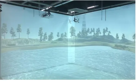
[image:2.595.79.518.214.331.2]Since the fusion function of the same plane can only solve the situation that two projectors are playing in the same plane, it cannot solve the situation that the projectors are playing in different planes. In the fusion of different plane projections, it is difficult for the projector to completely cover a certain section of the other side, most of which will appear as shown in figure 4, forming a bright band in the hexagonal region.
Figure 4. orthogonal projection without fusion effect.
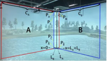
Therefore, this paper proposes a fusion function for right-angle surface fusion. Suppose two projection images A and B are spliced together to form a fusion band, where the length of the region of the fusion band removed in figure A and figure B are CA and CB respectively, and the
length of the fusion band is LA+LB. PA and P𝐴̂ is B projector in A on the surface of the boundary
[image:2.595.190.408.570.700.2]respectively is A and B point up and down below. Since the projection is an irregular hexagon on different planes, in order to facilitate the calculation of the fusion function, we need to transform it into a regular rectangle by geometric correction, as shown in figure 5.
Figure 5. Schematic diagram for setting parameters of right-angle projection.
The calculation method of the fusion function of image A and image B is shown in (3) and (4).
brightA =
{ 𝑎 (𝐿 𝑥
𝐴+𝐿𝐵) 𝑓(𝐶𝐴+ 𝑥) 𝑦 ∈ (𝑓𝐴̂𝐶̂(𝑥), 𝑓AC(𝑥)), x ∈ (0, L𝐵)
𝑎 (𝐿 𝑥
𝐴+𝐿𝐵) 𝑓(𝐶𝐴+ 𝑥) x ∈ (L𝐵, L𝐴+ 𝐿𝐵)
𝑓(𝐶𝐴+ 𝑥) 𝑜𝑡ℎ𝑒𝑟𝑠
(3)
brightB =
{
[1 − 𝑎 (𝐿 𝑥
𝐴+𝐿𝐵)] 𝑓(𝑥) x ∈ (0, 𝐿𝐵)
[1 − 𝑎 (𝐿 𝑥
𝐴+𝐿𝐵)] 𝑓(𝑥) 𝑦 ∈ (𝑓𝐵̂𝐶̂(𝑥), 𝑓𝐶𝐵(𝑥)), x ∈ (L𝐵, L𝐴+ 𝐿𝐵)
𝑓(𝑥) 𝑜𝑡ℎ𝑒𝑟𝑠
(4)
BrightA and brightB are the brightness of projection A and B in the fusion zone, respectively. 𝑓𝐴𝐶(𝑥) is the linear equation of PA and PC:𝑓𝐴𝐶(𝑥) = 𝑘𝐴𝐶𝑥 + 𝑏𝐴𝐶, 𝑓𝐵𝐶(𝑥) is the linear equation of
PB and PC:𝑓𝐵𝐶(𝑥) = 𝑘𝐵𝐶𝑥 + 𝑏𝐵𝐶, 𝑓𝐴̂𝐶̂(𝑥) is the linear equation of P𝐴̂ and P𝐶̂: 𝑓𝐴̂𝐶̂(𝑥) = 𝑘𝐴̂𝐶̂𝑥 + 𝑏𝐴̂𝐶̂, 𝑓𝐵̂𝐶̂(𝑥) is the linear equation of P𝐵̂ and P𝐶̂: 𝑓𝐵̂𝐶̂(𝑥) = 𝑘𝐵̂𝐶̂𝑥 + 𝑏𝐵̂𝐶̂.
Each linear equation is obtained from the coordinates of the corresponding two points. For example, the equation 𝑓𝐴𝐶(𝑥) = 𝑘𝐴𝐶𝑥 + 𝑏𝐴𝐶 is obtained from the linear equation constructed by the two points PA and PC.
Mixed Attenuation Function
In this paper, a mixed attenuation function is proposed to solve the attenuation problem in the fusion band. The mixed attenuation function uses the combination of exponential attenuation function and triangular attenuation function. In paper [6], an exponential attenuation function is proposed to solve the attenuation problem of the fusion band brightness, as shown in formula (5).
𝑎𝑅(𝑥) = 𝛼𝑥𝑝 0 ≤ 𝑥 ≤ 1
𝑎𝐿(𝑥) = 1 − 𝛼𝑥𝑝 0 ≤ 𝑥 ≤ 1 (5)
Figure 6. Schematic diagram of exponential decay function.
The trigonometric attenuation function uses the mathematical property of the trigonometric function 𝑠𝑖𝑛2𝑥 + 𝑐𝑜𝑠2𝑥 = 1 to attenuate the basic point[7], as shown in formula 6.
𝑎𝑅(𝑥) = 𝛽𝑠𝑖𝑛2(𝜋
2𝑥) 0 ≤ 𝑥 ≤ 1 𝑎𝐿(𝑥) = 𝛽𝑐𝑜𝑠2(𝜋
2𝑥) 0 ≤ 𝑥 ≤ 1
(6)
The triangular attenuation function has a significant improvement in the transition between the fusion zone and the non-fusion zone, but the brightness of the region in the middle of the fusion zone decayed so rapidly that there is a dark zone, and the dark zone gets darker and darker as the pixel gets closer to the center zone.
Appears in order to solve the above of the fusion zone regional to merge with the brightness of the inconsistent problem, the proposed hybrid damping function, adopts the exponential decay function and triangle combination of attenuation function, as described in formula 7, when x close to 1 triangle attenuation function of proportion bigger, close to zero exponential decay function accounted for a larger proportion.
𝑎𝑅(𝑥) = (1 − 𝑚𝑥)𝑛𝛼𝑥𝑝+ (𝑚𝑥)𝑛𝛽𝑠𝑖𝑛𝑞(𝜋
2𝑥) 0 ≤ 𝑥 ≤ 1 𝑎𝐿(𝑥) = (𝑚𝑥)𝑛(1 − 𝛼𝑥𝑝) + (1 − 𝑚𝑥)𝑛𝛽𝑐𝑜𝑠𝑞(𝜋
2𝑥) 0 ≤ 𝑥 ≤ 1
(7)
Experimental Results and Analysis
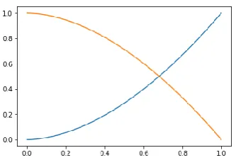
The effect of exponential decay function is shown in figure 7 (a). After repeated experiments, it can be known that the best effect is achieved when 𝛼 = 0.9 and p= 0.8. The effect of triangular attenuation function is shown in figure 7 (b). After repeated experiments, it can be known that the effect is best when 𝛽 = 1.
(a) (b)
Figure 7. Effect of exponential decay function and triangular attenuation function.
[image:4.595.94.484.575.707.2]Figure 8. Effect of mixed attenuation function.
It can be seen that the mixed attenuation function proposed in this paper can combine the advantages of exponential attenuation function and triangular attenuation function, and improve their disadvantages in different areas.
The mixed attenuation function combines the advantages of uniform brightness in the fused zone in the exponential attenuation function and the advantages of natural transition between the fused zone and the non-fused zone in the triangular attenuation function. In addition, it can solve the problem that the transition from the non-fused zone of exponential decay function to the fused zone in figure 7 is not smooth enough, and the brightness of the region in the middle of triangle decay function fusion zone in figure 8 is attenuated so rapidly that there is a dark belt and the dark belt gets darker and darker as the pixel point approaches the center.
Conclusion
Multi-plane projection display provides high resolution and seamless super large picture through the Mosaic display of multiple projectors. Aiming at the problem of projection Mosaic display of different planes, this paper proposes a method for the fusion area in different planes. In the multi-plane projection display system, this method can effectively fuse the edges of different projections without affecting the previous geometric correction steps, thus improving the image quality and viewability.
References
[1] Ramesh Raskar, Jeroen van Baar. Low-cost multi-projector curbed screen displays [J]. SID, 2005, 36(1): 884-887.
[2] Aditi Majumder. Luminance management for seamless multi-projector displays [J]. SID, 2005, 36(1): 1056-1057.
[3] RASKAR R. Immersive planar display using roughly aligned projectors [C/OL] // Proceedings of IEEE Virtual Reality 2000. [2013-12-01]. http: // web.media. mit. edu / ~raskar / UNC / Planar / raskarImmDisplay. Pdf.
[4] Li K, Chen Y. Optical blending for multi-projector display wall system [C] // Lasers and
Electro-Optics Society 1999 12th Annual Meeting. LEOS: IEEE, 1999: 281-282.
[5] Brown M, Lowe D G. Automatic panoramic image stitching using invariant features [J]. International Journal of Computer Vision, 2007, 74(1): 59-73.
[6] Wang Shengzheng, Yang Jie. Auto-nonlinear geometry calibration and edge blending of multi-projector display system[J]. Shanghai Jiaotong Daxue Xuebao/Journal of Shanghai Jiaotong University, 2008, 42(4): 574-578(in Chinese).