2018 International Conference on Computer, Communication and Network Technology (CCNT 2018) ISBN: 978-1-60595-561-2
Super-resolution Imaging by Two-photon Structured
Illumination Microscopy
Fan LIU, Shu-rong JIANG, Yan-hui WANG, Qing-ru LI and Han ZHANG
*College of Electrical Engineering and Information technology, Sichuan University, Chengdu, China
*Corresponding author
Keywords: Structured illumination microscopy, Two-photon laser scanning microscopy, Super-resolution.
Abstract. The application of two-photon excitation to confocal laser scanning microscope (CLSM)
leads two-photon laser scanning microscopy (TPLSM) to become an important tool in biology. The simultaneous absorption of two photons can reduce the phototoxicity and scattering, which can realize better imaging depth and high quality image. However, the spatial resolution of TPLSM is limited by optical diffraction, which is a barrier for its application. Structured illumination microscopy (SIM) offers rapid imaging speed for living cells and resolution enhancement by a factor of two. In this paper, we propose a nonlinear two-photon structured illumination microscopy (NTPSIM) that combines SIM with two-photon excitation, enabling resolution in thick specimens imaging twice of the normal resolution. Our method has the ability of less scattering and better depth penetration. Through theoretical simulation, we demonstrated that NTPSIM can improve imaging resolution significantly and provide strong penetrability with rapid imaging speed.
Introduction
Fluorescence microscope’s real-time dynamic imaging ability of living cells and the advantage of specificity mark make it widely used in the life science, materials, and polymer field [1]. The resolution of the conventional fluorescence microscopy is limited by the optical diffraction. This limit is a barrier for researchers to observe more precise structure. In recent years, various super-resolution fluorescence microscopy techniques about breaking the diffraction limit can be divided into two groups [2]. The first group is based on the single molecular localization microscopy (SMLM), such as photoactivated localization microscopy (PALM) [3], fluorescent photoactivated localization microscopy (FPALM) [4], and stochastic optical reconstruction microscopy (STORM) [5]. Another group employs the nonlinear effects or the transformation of illumination to improve resolution, including stimulated emission depletion (STED) microscopy [6], and structured illumination microscope (SIM) [7]. SMLM has high resolution but restrained by its slow imaging speed [7-10]. Also, the applications of total internal reflection fluorescence (TIRF) improve the signal-to-noise (SNR) of images but sacrifice the depth of imaging [11]. STED has high imaging speed, but the resolution of STED microscopy is easily degraded by the depth-dependent aberrations [12].
Theory and Simulation
Traditional microscopic imaging process can be written as:
( ) [ ( ) ( )] ( )
P r = I r ×O r ⊗psf r
(1) In the above equation, I(r) is the illumination pattern. O(r) is the object sample, and psf(r) represents the point spread function of the microscope imaging system. In traditional microscopy, I(r) is uniform, and it can only observe the information that within a circular region in frequency domain [20]. In linear SIM, the illumination pattern change to stripe illumination pattern, and the moire fringe is used to move the high frequency information into the region from the outside to make it visible so that the resolution can be improved. In the two dimensional linear SIM, I(r) can be represented by the following equation:
( ) 2 cos(2 x x) cos(2 y y)
I r = + πk x+ϕ + πk y+ϕ
(2) kx and ky are the frequency of the stripes in the x and y direction, and the frequency of both directions in single photon SIM is set to k0 in this paper. In Fourier space, the illumination pattern is represented by Eq. 3, and Cn is the strength coefficient of nth harmonic.
1 1
1 1
( ) ( ) xx ( ) y y
x y
in in
x x x x y y y y
n n
I K Cn δ K n k e− ϕ Cn δ K n k e− ϕ
=− =−
=
∑
× + +∑
× +(3) The frequency domain expression of Eq. 1 is shown in Eq. 4. After multiplying the simulated object by structured illumination pattern, the +1, and -1 frequency domain components in x, y directions (D(k), D(kx-k0), D(kx+k0), D(ky-k0), D(ky+k0)) are moved into the range of OTF (OTF is the Fourier transform of PSF).
1 1
1 1
( ) ( ) x x ( ) y y
x y
in in
x x x x y y y y
n n
P K Cn D K n k e− ϕ Cn D K n k e− ϕ
=− =−
=
∑
× + +∑
× +(4) By multiplying the simulated object and five different phase illumination patterns, different original images can be obtained, and take original images to FFT. The information of different frequencies will be separated for the image construction by solving 5×5 equations from Eq. 4. Then, the frequency domain of the super-resolution image could be obtained. After the IFFT, the final super-resolution image is retrieved.
In the two dimensional NTPSIM (2D-NTPSIM), the wavelength of two-photon excitation is twice the wavelength of single photon excitation [21], so when the wavelength is changed, the frequency of effective illumination pattern becomes half. And the effective illumination pattern of the 2D-NTPSIM is represented by Eq. 5, where kx and ky are k0/2. And the effective illumination pattern is shown in Figure 1(a), and the 2D-NTPSIM effective illumination pattern of frequency domain expression is Eq. 6.
2
( )double 2 cos(2 x x) cos(2 y y)
I r = + πk x+ϕ + πk y+ϕ
(5)
( )double ( ) ( )
I k =I k ⊗I k
(6)
simultaneous absorption of three photons is difficult to realize in practical application, so we mainly discuss the imaging process of NTPSIM.
3
( )three 2 cos(2 x x) cos(2 y y)
I r = + πk x+ϕ + πk y+ϕ
(7)
( )three ( )double ( )
I k =I k ⊗I k
(8)
(a) (b)
Figure 1. (a)Effective illumination pattern of 2D-NTPSIM. (b)Effective illumination pattern of 2D three-photon SIM.
From Eq. 7, the object which illuminated by the two-photon structured illumination pattern will contain 13 different frequency information. Therefore, 13 pairs of two-photon structured illumination pattern with different phases are needed to obtain the original images, and then through the separation of the information, different frequencies information could be acquired for image recombination. Similarly, it contains 25 pieces of information after the object illuminated by the three-photon structure illumination pattern, and then 25 original images are required to obtain the information of 25 different frequencies and reconstruct the super-resolution Fourier image. The final result can be obtained after IFFT. The reconstruction process of 2D-NTPSIM is described in Figure 2.
Figure 2. (a)The Simulated object contains three circles spacing at 250 nm and 150 nm, and four pairs of vertical bars spacing at 250, 150, 130, 120 nm respectively. (b) Effective illumination patterns. (c) Airy disk (point separated function).
(d) Raw images. (e) Raw images in frequency domain. (f) Different frequency information in frequency domain. (g) The super-resolution frame in frequency domain. (h) The Super-resolution frame. The frames in frequency
domain are all log-converted and the colors are limited to make them visible.
500nm 750nm
(a) (b) (c) (d) (e)
(h) (g) (f)
250 nm
150 nm 130 nm
In Figure 2(h), which is the desired super-resolution image, the pairs of bars can be distinguished when the bar’s spacing is beyond 130 nm. Thus, the resolution of reconstructed images can be improved by a factor of two.
Discussion
In the simulation of 2D-NTPSIM, we developed two imaging methods. One is described in the above simulation, which is 2D-NTPSIM. Another is by changing the orientation angle of illumination pattern basing on the one-dimensional SIM, so that the resolution can be improved in all directions to realize two-dimensional super-resolution imaging. The frequency domain information of one-dimensional two-photon SIM consists of five parts (0, +kx, -kx, +2kx, -2kx). Then changing the direction of kx and sweeping the entire field to realize wide field super-resolution imaging. The reconstruction process of rotary NTPSIM is shown in Figure 3.
In the simulation of rotary NTPSIM, multiplying the simulated object by the illumination patterns with different orientation and phase, and convoluting with airy disk could get different raw frames. Next, we separate information in different frequency in the space domain according to Eq. 4. In order to improve the accuracy of information shift distance, we use the translation characteristics of the Fourier transform to carry out the shift, such as Eq. 9. Thus, in space domain, multiplying the separated information by coefficient shown in Figure 3 and merging the images together can obtain the super-resolution frame.
2
( ) ( ) i nkx
x
D K±nk =D r e∓ π
(9)
Figure 3. (a) Simulated objects. (b) Different orientation angle (0°, 30°, 60°, 90°, 120° and 150°) and phase of the effective illumination patterns. (c) Airy disk. (d) Raw images. (e) Different-frequencies of object in space domain. (f)The varied information shifted to the original position. (g) Reconstructed images in different orientation angles. (h) Super-resolution image.
(a) (b) (c)
(f) (e) (d)
(g) (h)
Merge local
images together Merge local
images together Information separation
2 x
i k
e± π ×
⊗ ×
250 nm
150 nm 130 nm
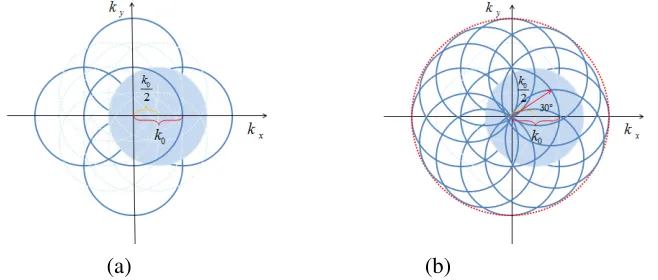
The set of low-frequency information that can be observed by the conventional microscope is a circular observable region of radius 1/k0 in frequency domain. A long-wavelength excitation light will decrease the shift distance of high-frequency domain (kx and ky decrease). In the process of image reconstruction, repetition of the frequency domain information that is moved back to original positions will create more artifacts.
Therefore, without losing any frequency domain information, we only add the outside frequency domain information and the origin frequency domain information (the area represented by the blue circle in Figure 4) and ignore the light blue circle in the image reconstruction for less artifacts.
(a) (b)
Figure 4. (a)The frequency domain diagram of the reconstructed image of 2D-NTPSIM. (b)The frequency domain diagram of the reconstructed image with the orientation angle 0°, 30°, 60°, 90°, 120° and 150°.
Comparing two imaging methods through the simulation of the imaging construction process, the 2D-NTPSIM is based on frequency domain, and the rotary NTPSIM is based on space domain. For rotary NTPSIM, when the orientations of pattern can cover all directions, the resolution is uniform in all directions, as shown in Figure 4(c). However 2D-NTPSIM’s resolution in ~45 ° and ~135 ° directions is smaller than x and y axis, as shown in Figure 2(h) and Figure 4(a). And, in practical application, kx is usually not an integer, thus, the accuracy of information shift distance in 2D- NTPSIM is not better than rotary NTPSIM. In the process of image recombination, the 2D-NTPSIM adds multiple low-frequency information, while the rotary NTPSIM adds low-frequency information only once. Comparing the super-resolution image reconstructed by the two methods (Figure 2 and Figure 3), the artifacts in Figure 2 are more significant. Therefore, the method of image reconstruction in rotary NTPSIM is better than 2D-NTPSIM.
Summary
To sum up, the NTPSIM can improve the resolution by a factor of two with fast imaging speed. According to the theoretical simulation, compared with 2D- NTPSIM, the rotary NTPSIM offers better accuracy of displacement in practical practice and the resolution is more uniform with less artifacts. NTPSIM can provide high SNR and anti-noise capability without decrease of resolution. And in the TPLSM imaging process, the stimulation of two-photon deepen imaging depth. These characteristics improve the imaging quality greatly, making NTPSIM have extensive application prospect in the field of thick tissues imaging. We believe it can promote the application of super-resolution imaging in biological medicine, polymer material science, etc.
Acknowledgement
[image:5.612.173.502.179.319.2]References
[1]Huang B, Babcock H, Zhuang X. Breaking the Diffraction Barrier: Super-Resolution Imaging of Cells[J]. Cell, 2010, 143(7):1047-58.
[2]Huang B, Bates M, Zhuang X. Super resolution fluorescence microscopy[J]. Annual Review of Biochemistry, 2009, 78(1):993.
[3]Betzig E, Patterson G H, Sougrat R, et al. Imaging intracellular fluorescent proteins at nanometer resolution.[J]. Science, 2006, 313(5793):1642-1645.
[4]Hess S T, Girirajan T P, Mason M D. Ultra-high resolution imaging by fluorescence photoactivation localization microscopy.[J]. Biophysical Journal, 2006, 91(11):4258-4272.
[5]Klar T A, Hell S W. Subdiffraction resolution in far-field fluorescence microscopy[J]. Optics Letters, 1999, 24(14):954-956.
[6]Bates M, Huang B, Rust M J, et al. Sub-Diffraction-Limit Imaging with Stochastic Optical Reconstruction Microscopy[J]. Nature Methods, 2010, 3(10):793.
[7]Hell S W, Wichmann J. Breaking the diffraction resolution limit by stimulated emission: stimulated-emission-depletion fluorescence microscopy.[J]. Optics Letters, 1994, 19(11):780-782.
[8]Klar T A, Jakobs S, Dyba M, et al. Fluorescence microscopy with di raction resolution barrier broken by stimulated emission[J]. Proceedings of the National Academy of Sciences of the United States of America, 2000, 97(15):8206-10.
[9]Wen G, Li S, Yang X, et al. Super-Resolution Fluorescence Microscopy System by Structured Light Illumination Based on Laser Interference[J]. Acta Optica Sinica, 2017, 37(3):0318003.
[10]Herbert S, Soares H, Zimmer C, et al. Single-Molecule Localization Super-Resolution Microscopy: Deeper and Faster[J]. Microscopy & Microanalysis, 2012, 18(6):1419-1429.
[11]Gould T J, Burke D, Bewersdorf J, et al. Adaptive optics enables 3D STED microscopy in aberrating specimens.[J]. Optics Express, 2012, 20(19):20998-1009.
[12]Yeh C H, Chen S Y. Resolution enhancement of two-photon microscopy via intensity-modulated laser scanning structured illumination.[J]. Appl Opt, 2015, 54(9):2309-2317.
[13]Winter P W, Chandris P, Fischer R S, et al. Incoherent structured illumination improves optical sectioning and contrast in multiphoton super-resolution microscopy.[J]. Optics Express, 2015, 23(4):5327-34.
[14]Winter P W, York A G, Nogare D D, et al. Two-photon instant structured illumination microscopy improves the depth penetration of super-resolution imaging in thick scattering samples.[J]. Optica, 2014, 1(3):181-191.
[15]Takasaki K T, Ding J B, Sabatini B L. Live-cell super resolution imaging by pulsed STED two-photon excitation microscopy[J]. Biophysical Journal, 2013, 104(4):770-777.
[16]Gustafsson M G.2000. Surpassing the lateral resolution limit by a factor of two using structured illumination microscopy[J]. Journal of Microscopy, 198(2):82–87.
[17]Denk W, Strickler J H, Webb W W. Two-Photon Laser Scanning Fluorescence Microscopy[J]. Science, 2007, 248(4951):73-76.
[19]Heintzmann R, Jovin T M, Cremer C. Saturated patterned excitation microscopy--a concept for optical resolution improvement.[J]. Journal of the Optical Society of America A Optics Image Science & Vision, 2002, 19(8):1599-1609.
[20]Chen D. Two-Photon Laser Scanning Fluorescence Microscopy and its Applications[J]. Physics, 2000, 248(4951):73-6.
[21]Wu M, Yang X, Xiong D, et al. Structured Illumination Fluorescence Microscopy: Diffraction-Limit Breaking Principle and Application in Life Science[J]. Laser & Optoelectronics Progress, 2015, 52(1):17-27.