2018 International Conference on Physics, Computing and Mathematical Modeling (PCMM 2018) ISBN: 978-1-60595-549-0
Numerical Simulation of the Separation Flow Field
in a Gravitational Oil-water Separator
Long LIANG*, Zhi-shan BAI and Xiao-yong YANG
School of Mechanical and Power Engineering, East China University of Science and Technology, Shanghai 200237, China
*Corresponding author
Keywords: Numerical simulation, Corrugated plate, Opening ratio, Phase interface.
Abstract. The RNG k-ε model and Euler model are used to simulate the internal flow field of the corrugated plate separator. By comparing the pressure drop and the interfacial distribution of oil and water at different opening ratios, we obtain the coalescence characteristics of corrugated plates. The results show that the corrugated plate pressure drop decrease with the increase of the opening ratio. The higher the opening ratio is, the slower change of pressure drop along the flow channel is. The interfacial area of oil and water decreases first and then slowly increases with the increase of opening ratio, and reaches the maximum after the corrugated plate with opening ratio of 0%, and gets the minimum after the corrugated plate with opening ratio of 10%, which means the best opening ratio is about 10%. The hole in the corrugated plate can eliminate the barrier of the corrugated plate to the oil phase and promote the floating rise of the oil phase which means the corrugated plate with holes has good separation effect.
Introduction
The earliest application of corrugated plate coalescence separator appeared in the US, and it has been widely concerned by industry researchers and engineering technicians since its birth [1]. Based on two separation methods of gravity settlement and coalescence, a large number of researchers have studied the corrugated plate by numerical simulation method [1-4]. The flow in the corrugated plate is very complex and many research results show that the chaotic flow is very beneficial to the collision of droplets and improve the separation efficiency [5]. There are many factors affecting the internal flow, such as corrugated plate spacing, corrugated plate angle and plate peak height [6]. Different plate types, such as parallel plates. snake shaped plate and interlaced corrugated plate, will also affect the internal flow field and separation efficiency [2,7] . Orifice plate corrugated structured packing has higher separation efficiency [8,9]. The smaller the space of the plate is, the higher the separation efficiency is, but the pressure drop will increase with the decrease of plate spacing [10,11] . The structural parameters of corrugated plate will not only affect the internal flow field, but also affect the distribution of dispersed phase inside it [12]. The corrugated plate material will also have a great influence on the separation efficiency which means that the application of the oil-bearing corrugated plate has a higher separation efficiency in the oil and water separation[13-16]. However, there are few reports about the influence of corrugated plate opening ratio on the separation flow field and oil-water interfacial area.
Through the numerical simulation of the internal flow field and the oil-water interface in the corrugated plate separator, the influence of the opening ratio on the pressure drop and the oil-water interface is analyzed, which provides some reference for the structure design of the oil-water separator and the selection of the type of the corrugated plate structured packing.
Numerical Modeling
Geometric Model
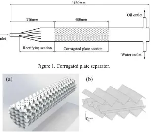
The placement of corrugated plates is shown in Fig.2. A complete flow channel with 7 cycles in a corrugated plate structured packing is shown in Fig.3. The wavelength of the corrugated plate is 16mm, and the hole position is at the angle of the corrugated plate. The channel between the two plates is divided into upper and lower flow channels by the interface of the two plate.
Figure 1. Corrugated plate separator.
Figure 2. (a). A three-dimensional model of perforated corrugated plate, (b). Interlaced corrugated plate.
Figure 3. A complete flow channel in corrugated plate with holes.
Control Equations
Fluid phase is treated as a continuum by solving the Navier–Stokes equations. Mass conservation equation:
( )
div U 0 (1)
Momentum conservation equation
X-direction:
( )
( ) xx yx zx
u p
x t div uu x x y z F
(2)
Y-direction:
( )
( ) xy yy zy
v p
y t div vu y x y z F
(3)
Z-direction:
( )
( ) xz yz zz
w p
z t div wu z x y z F
(4)
[image:2.595.150.447.427.518.2]Turbulence
The traditional way of dividing the flow state is based on the circular pipe flow. For corrugated plate packing, it is generally considered that the Reynolds number 135 is the boundary between laminar flow and transitional flow in corrugated packing[17]. Therefore, the RNG k-ε turbulence model is used to close the turbulent equation. The equations for the turbulence kinetic energy k and the turbulence dissipation rate ε can be described by Eq.(5) and Eq.(6) respectively:
i ( )
i j j
k
k eff k b x ku x a x G G
(5)
( )
i i i eff i k b
x x a x C k G C G C k R
2
1 3 2 (6)
In the equation, Gk is the generation of turbulence kinetic energy due to mean velocity gradients, Gb is the generation of turbulence kinetic energy due to buoyancy, ak and aε are the inverse effective
Prandtl numbers for k and ε respectively, μeff is the effective viscosity, C1ε, C2ε, C3ε are turbulence
model constants, Rε accounts for the effects of rapid strain and streamline curvature.
Multiphase Flow Model
The fluent software in a multiphase model is used to simulate the coalescence of oil and water separation. The multiphase models include volume of fluid (VOF), mixture, Euler and discrete phase model. VOF model is only used to solve the phase interface flow conditions problems. Technically speaking, the mixture and Euler model are both available for the condition, but only Euler model can fit the simulation of the surface modification and the coalescence plate structure. So Euler model is used for the condition.
Boundary Condition and Grid Independence
Boundary Condition Settings
Velocity inflow boundary was set at the inlet.
All wall surfaces are set to non-slip wall conditions, and the standard wall function is adopted. Water phase and oil phase outlet are both set to free outflow boundary conditions.
Grid Independence
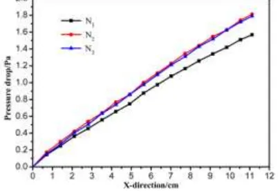
[image:3.595.198.399.606.745.2]Three sets of different numbers of grids are established for the model, namely N1=17 million, N2=33.5 million and N3=41 million. As shown in Fig.4, in the calculation results of pressure drop along the channel, the calculation accuracy of N2 is significantly better than that of N1. When the number of grids continues to increase to N3 million, the accuracy of computation has not changed significantly. The maximum relative error between grid number N2 and N3 is 7.12%, which is within the allowable range. Therefore, the number of N2 grids is used to calculate the model.
Results and Discussion
The Influence of Opening Ratio on Pressure Drop
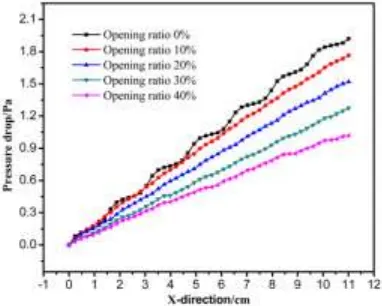
As shown in Fig.5, when the opening ratio is 0%, the pressure drop along the ladder rises step by step, and the variation curve has 7 ladders. Meanwhile, 7 cycles are observed in a complete flow channel in Figure 3, and the position of the ladder in the pressure drop curve corresponds to the location of each cycle in the flow channel. The reason of this phenomenon is that the plate corner in the flow channel disturbs the flow, affects the fluid flow and causes the increase of local pressure loss at the angle of the plate, thus the ladder shape in the pressure drop curve appears. It can be obtained from Fig.5 that the greater the opening ratio is, the slower the change of pressure drop along the flow channel is, which means that the high opening ratio can reduce the pressure loss inside the corrugated plate structured packing. And when the opening ratio is above 10%, the ladder change trend of pressure drop along the flow channel will disappear. The reason of this phenomenon is that the hole is located at the corner of plate, and the greater the opening ratio, the less the influence of the plate corner on the fluid flow, thus the severe change area of the pressure drop in the flow passage is eliminated, which means the flow is more stable and the pressure loss is reduced.
[image:4.595.203.394.405.558.2]Fig.6 is the effect of different opening ratio on pressure drop of corrugated plate section. It can be seen from Fig.6 that the pressure drop of the corrugated section decreases with the increase of the opening ratio, which indicates that the greater the opening ratio is, the lower the pressure drop of corrugated plate section is. This is because the holes in the corrugated plate are all located at the plate corner of the corrugated plate, and the existence of holes can weaken the effect of the plate corner on the pressure drop, making the loss of the pressure drop in the opening corrugated plate lower.
[image:4.595.201.397.585.723.2]Figure 5. The change of pressure drop in the flow channel under different opening ratios.
Figure 6. The pressure drop of corrugated plate varies with different opening ratios.
The Influence of Opening Ratio on Oil-water Two-phase Interface
opening ratio of 0%. This shows that the corrugated plate has a positive effect on the accumulation of oil phase. At the same time, it can be found that the corrugated plates with opening ratio of 0% has an insulating effect on the oil phase, which hinders the further rise of the oil phase in the corrugated plate. In the corrugated section with opening ratio of 10%, the larger volume fraction of oil phase is at the top of the separator. The oil volume fraction increases from the bottom to the top of the separator. The reason of this phenomenon is that the holes provide channels for the cross layer floating of the oil phase, so that the oil phase at the bottom of the separator can continue to float up to the top through the holes. Therefore, the orifice plate corrugated packing not only has the same accumulation effect on the oil phase, but the holes can also act as the convenient channel for oil phase floating, eliminate the isolation effect of the corrugated plate and enhance the separation effect of oil and water two phase.
Figure 7. Contour of oil volume fraction on the cross section of the corrugated plate section.
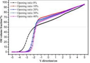
[image:5.595.208.393.644.774.2]Fig.8 is the oil volume fraction on the cross section of the separator at 10cm after corrugated plate section. The area in which the oil volume fraction ranges from 0% to 60% is set to be the oil-water phase interface. The size of the area can be quantitatively analyzed by the width of the two-phase interface. It can be obtained from Fig.8 that after the corrugated plate with opening ratio of 0%, the width of oil-water phase interface is about 4cm, and there is a higher oil volume fraction of oil phase at the bottom of the separator. The widths of the two phase interface after the corrugated plate with four opening ratios of 10-40% are 0.7cm, 0.9cm, 1.0cm, 1.2cm separately which are much smaller than that after corrugated plate with opening ratio of 0%. This means that holes on corrugated plates can effectively reduce the interfacial area of oil-water. It can be seen from Fig.8 that the oil volume fraction on the upper part of the separator decreases with the increase of opening ratio, which means the coalescence effect of corrugated plates on oil phase will be reduced when the opening ratio is larger than 10%. Considering the effect of corrugated plates on coalescence of oil phase, we find that as the opening ratio increases, the surface area of the corrugated plate is reduced, which is not conducive to the accumulation and growth of the oil droplets on the surface of the plate, and the volume fraction of the oil phase on the upper part of the separator shows a downward trend. Therefore, although the increase in opening ratio is beneficial to reducing the pressure drop of the corrugated plate section, considering the effect of oil and water separation and the rectifying of the corrugated plate, the opening ratio is not suitable to be too large. By comparison, the corrugated plate used for oil and water separation can obtain more effective separation when the opening ratio of the corrugated plate is around 10%.
Model Validation
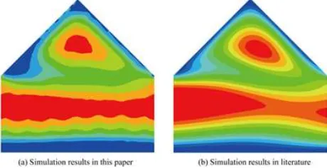
[image:6.595.184.414.190.308.2]The simulation results in this paper are compared with the simulation results in the literature [17], in order to validate the reliability of the CFD simulation results. As shown in Fig.9, the flow fields are similar, and the simulation results agree well with each other. But there are some differences between the two flow fields. The reason for this phenomenon is that only a structured packing unit is simulated in the literature without considering the interaction between packing elements. The interaction between packing elements is taken into account in this paper. Therefore, it is feasible to study the flow characteristics in corrugated plates through this model.
Figure 9. Comparison of the simulation results in this paper and in the literature.
Conclusions
The RNG k-ε model and Euler model are used to simulate the internal separation flow field in the corrugated plate with different opening ratio, to simulate the internal flow field in the corrugated plate and the concentration distribution of oil phase in the separator. As a result, this model can reflect the flow field in corrugated plate separator accurately.
Through the analysis of the pressure drop in the corrugated plate separator, the result shows that the pressure drop of the corrugated plate flow channel rises in a ladder shape, and the holes can weaken the influence of the plate corner to the pressure drop. The greater the opening ratio, the lower the pressure drop of the corrugated plate, and the slower variation of the pressure drop in the flow channel.
Through the analysis of the distribution range of oil-water phase interface, the result shows that the corrugated plate has the isolation effect on the oil phase, hinders the floating rise of the oil phase. The oil-water phase interface is wider after the corrugated plate with opening ratio of 0%, and obtains the least width after the corrugated plate with opening ratio of 10%, which realizes better separation efficiency.
References
[1]Han Y, He L, Luo X, et al. A review of the recent advances in design of corrugated plate packs applied for oil-water separation[J]. Journal of Industrial and Engineering Chemistry, 2017, 53: 37-50.
[2]Tavakoli E, Hosseini R. Numerical analysis of 3D cross flow between corrugated parallel plates in evaporative coolers[J]. Energy Conversion and Management, 2011, 52(2): 884-892.
[3]Li Z, Gao Y. Numerical study of turbulent flow and heat transfer in cross-corrugated triangular ducts with delta-shaped baffles[J]. International Journal of Heat and Mass Transfer, 2017, 108: 658-670.
[4]Sun F D. Numerical simulation on liquid flow characteristics of the wavy plate[J]. Modern Chemical Industry, 2012, 32(1): 90-93.
[6]Wang G, He L, Lu Y, et al. Study on oil-water separating behavior of gravity separator[J]. Shiyou Xuebao/Acta Petrolei Sinica, 2006, 27(6): 112-115.
[7]Zhang M, Wang L, Nie F, et al. Study on hydrodynamic performance of corrugated plate packing[J]. Chemical Industry & Engineering Progress, 2012, 31(11): 2411-1273.
[8]Yayla S, Ibrahim S S, Olcay A B. Numerical investigation of coalescing plate system to understand the separation of water and oil in water treatment plant of petroleum industry[J]. Engineering Applications of Computational Fluid Mechanics, 2017, 11(1): 184-192.
[9]Sun Z, Jin Y, Wang Z, et al. Effect of coalescing internal structures acting on oil-water separating performance of gravity separator[J]. Ciesc Journal, 2010.
[10]Zhang L-h, Xiao H, Zhang H-t, et al. Optimal design of a novel oil–water separator for raw oil produced from ASP flooding[J]. Journal of Petroleum Science and Engineering, 2007, 59(3-4): 213-218.
[11]Fan Y G, Zhang L F, Yuan S X, et al. Numerical Simulation of Corrugated Plate Separation Performance with Different Plate Spacing and Dip Angles[J]. Petro-Chemical Equipment, 2015.
[12]Ivanenko A Y, Yablokova M A, Petrov S I. Simulation of the separation of emulsified oil products from water in an apparatus with sinusoidal-profiled oleophilic plates[J]. Theoretical Foundations of Chemical Engineering, 2010, 44(5): 729-741.
[13]Wang X, Yan Y, Xu Z. Application experiment and numerical simulation analysis of oil–water separator with two-oriented corrugated coalescence plate[J]. Journal of Dispersion Science and Technology, 2016, 38(10): 1509-1515.
[14]Spielman L A, Su Y P. Coalescence of Oil-in-Water Suspensions by Flow through Porous Media[J]. Industrial and Engineering Chemistry Fundamentals, 1977, 16(2): 272-282.
[15]Zheng L, Du Y. Corrugated Board Coalescing Oil-Water Separateing Technology[J]. Oil-Gasfield Surface Engineering, 1994.
[16]Krasiński A. Separation of oil-in-water emulsions using polymer coalescence structures[J]. Environment Protection Engineering, 2016, 42(2): 19-39.