Open Access
Research article
Biomechanical comparison of a new stand-alone anterior lumbar
interbody fusion cage with established fixation techniques – a
three-dimensional finite element analysis
Shih-Hao Chen
1, Ching-Lung Tai
2, Chien-Yu Lin
3, Pang-Hsing Hsieh
4and
Weng-Pin Chen*
3Address: 1Department of Orthopaedics, Tzu-Chi General Hospital, Taichung, Taiwan, 2Graduate Institute of Medical Mechatronics, Department of Mechanical Engineering, Chang Gung University, Taoyuan, Taiwan, 3Department of Biomedical Engineering, Chung Yuan Christian University, Chungli, Taiwan and 4Department of Orthopaedic Surgery, Chang Gung Memorial Hospital, Taoyuan, Taiwan
Email: Shih-Hao Chen - [email protected]; Ching-Lung Tai - [email protected]; Chien-Yu Lin - [email protected]; Pang-Hsing Hsieh - [email protected]; Weng-Pin Chen* - [email protected]
* Corresponding author
Abstract
Background: Initial promise of a stand-alone interbody fusion cage to treat chronic back pain and restore disc height has not been realized. In some instances, a posterior spinal fixation has been used to enhance stability and increase fusion rate. In this manuscript, a new stand-alone cage is compared with conventional fixation methods based on the finite element analysis, with a focus on investigating cage-bone interface mechanics and stress distribution on the adjacent tissues.
Methods: Three trapezoid 8° interbody fusion cage models (dual paralleled cages, a single large cage, or a two-part cage consisting of a trapezoid box and threaded cylinder) were created with or without pedicle screws fixation to investigate the relative importance of the screws on the spinal segmental response. The contact stress on the facet joint, slip displacement of the cage on the endplate, and rotational angle of the upper vertebra were measured under different loading conditions.
Results: Simulation results demonstrated less facet stress and slip displacement with the maximal contact on the cage-bone interface. A stand-alone two-part cage had good slip behavior under compression, flexion, extension, lateral bending and torsion, as compared with the other two interbody cages, even with the additional posterior fixation. However, the two-part cage had the lowest rotational angles under flexion and torsion, but had no differences under extension and lateral bending.
Conclusion: The biomechanical benefit of a stand-alone two-part fusion cage can be justified. This device provided the stability required for interbody fusion, which supports clinical trials of the cage as an alternative to circumferential fixations.
Published: 18 June 2008
BMC Musculoskeletal Disorders 2008, 9:88 doi:10.1186/1471-2474-9-88
Received: 6 March 2008 Accepted: 18 June 2008
This article is available from: http://www.biomedcentral.com/1471-2474/9/88 © 2008 Chen et al; licensee BioMed Central Ltd.
Background
Lumbar interbody cages are an improvement in spinal fusion that facilitate stabilization of the motion of seg-ments and relieve discogenic back pain. They favor load transmission via the anterior column, annular fiber ten-sioning, restoration of the disc height and lordosis and have the least demands on bone graft volume [1-4]. The success of a fusion cage insertion, in addition to the bio-logical factors, may depend upon other mechanical parameters, including the material properties of the verte-brae, the geometry of the implants, and the interface between the cage and the bone [5-7]. Although initial sta-bility of the interbody spacers insertion is a requirement for successful fusion, the load transmission and its effect on the tissues adjacent to the fusion cage also play an essential role, which is not easily detectable with experi-mental tests [2,7,8]. Implantation of a single anterior interbody cage in a functional spinal unit has been inves-tigated using finite element analysis (FEA) to reveal the altered load transfer and the neighboring structural change in relation to the peak stress distribution on the cage-bone contact interface [9,10]. Further examination of the stabilization effects of several fusion cages on the same specimen under different loading conditions will provide a better insight into the amount to which certain factors may influence the clinical outcomes.
Conventional cage designs have either cylindrical or rec-tangular shapes, thick walls, and a hollow interior space that contains grafting materials. Cylindrical cages have threads along their entire length, whereas rectangular cages have serrated anchors on the upper and lower sur-faces. The rigid hollow design of fusion cages guarantees sufficient construct stiffness in arthrodesis and affords a substantial stability for the motion segments after spinal surgery, as well as shielding stress on the implanted graft [11,12]. The stability of a cage-buttressed fusion relies on the strong apophyseal part of the endplate for support, as well as the neighboring vertebrae ensuring sufficient den-sity in the peripheral region to tolerate the alternation of load transfer following cage insertion [7,13]. Failure of the implant-endplate interface may occur in an osteoporotic spine with cage subsidence, migration and subsequent loss of disc height [6,7,10]. The anterior stand-alone tradi-tional cage has been reported to reduce intervertebral motion in flexion and lateral bending, while no stabiliza-tion was achieved during extension and axial rotastabiliza-tion [2,5]. Although supplementation of posterior fixation diminishes residual segmental mobility and preserves lumbar lordosis, the optimal construct performance and all cage-bone interface mechanics have yet to be deter-mined. A newly designed two-part fusion cage consisting of a rectangular frame that accommodates a threaded cyl-inder holding bone graft material was developed. A bio-mechanical comparison between the two-part cage and
the conventional interbody spacers will be completed. The purpose of this study was to use FEA models to inves-tigate the cage-bone interface mechanics and stress distri-bution on the adjacent tissues after insertion of several interbody fusion cages with or without the supplementary posterior fixation. Based on the parametric measurement of contact stress on the facet joint, maximum slip dis-placement of the implants on the endplate, and rotational angle of the upper vertebra in relation to the peak stress of contact site, the biomechanical differences of several implanted constructs were assessed under different load-ing conditions.
Methods
Generation of L4-5 intact finite element model
A 27 year-old male with paraplegia scheduled for a com-puted tomography (CT) examination of the lumbar spine was recruited. A one-millimeter scan interval was used from the L4 to L5 vertebrae in the transverse direction and the data files were transferred to a personal computer for image processing. The contours of the cortical and cancel-lous bone were used to generate the solid model in the Solid Works CAD software (Solid Works Corp., Boston, U.S.A.). The surface models of the L4-5 vertebrae were transferred to a finite element pre-processing program – Mentat (MSC Software Corp., Los Angeles, U.S.A.) and the finite element mesh of the intact L4-5 vertebrae was gen-erated with 10-node tetrahedral elements. The determina-tion of the facet joints was difficult since there were only a few CT images across the facet joint. Therefore, the ori-entations and gaps of the facet joints were manually cre-ated according to literature [14]. The facet joints were assumed to be frictionless, had a gap of 0.5 mm, and could only transmit compressive force [15].
The dimension and position of the intervertebral disc were determined from the adjacent endplates. The nucleus pulposus and annulus fibrosis were modeled with solid elements with linear elastic material properties. All seven ligaments (anterior and posterior longitudinal liga-ments, ligamentum flavum, facet capsular ligament, inter-spinous ligament, suprainter-spinous ligament and intertransverse ligament) were included in the finite ele-ment model (FEM). These eleele-ments were modeled as ten-sion-only cable elements with linear elastic behavior. The insertion points, cross-sectional areas, and material prop-erties were adopted from anatomy textbook and various reports. The material properties for the different parts of the model were assigned according to previous literature as shown in Table 1[16-18]
finite element model of the L4-5 functional spinal unit consisted of 51322 elements.
Generation of models implanted with interbody spacers and posterior instrumentation
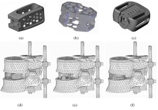
Using the anterior spinal approach and removal of the anterior longitudinal ligament, the following three differ-ent spacers were inserted to stabilize the anterior column for interbody fusion: (A) the Contact Fusion Cage (Stratec, Oberdorf, Switzerland) is a small rectangular cage in dual-parallel position, denoted as "DPC"; (B) the SynCage (Mathys Medical Ltd., Bettlach, Switzerland) is a single monobloc, box-shaped large cage, denoted as "SLC"; (C) the Stabilis (Stryker, Michigan, U.S.A.) device is made of two distinct parts – an anatomically rectangular frame with a threaded, cylindrical delivery unit of bone graft and is denoted as "TPC". The three cages are made of titanium alloy and have known material properties. The appropriate size of trapezoid 8° cage was chosen accord-ing to the space between the vertebrae, as proposed by the manufacturer to restore lumbar lordosis and disc height. Accordingly, a modulus of 110 GPa and Poisson's ratio of 0.3 were defined for titanium alloy (Table 1) [15]. The FEMs of the three different cages are shown in Figure 1a– c, respectively. The FEMs of the L4-5 motion segment implanted with three different cages are shown in Figure 1d–f, respectively.
The residual annulus of the operated intervertebral disc was ignored because it was likely to be compromised sig-nificantly by the anterior surgical procedure and because the stiffness of the remaining tissue would be very low as
compared to that of the interbody cage. Bone graft and bone ingrowth into the hollow interior space were not modeled in this study.
Contact definition
The interfaces between the cage and endplate were mod-eled with contact bodies. Slip displacement was defined as the relative micromotion on the implant-bone interface by calculating the length between two adjacent contact nodes on the contact bodies. For the definition of interac-tion between the implant and the bone, a Coulomb fric-tion contact algorithm was used to model the force transmission between implant and vertebral endplate. The coefficient of friction for the interaction was set to 0.4 for the benchmark case [19]. Commercially available implants often have serrated contact surfaces, creating higher effective friction coefficients than would be expected with smooth contact surfaces, which were mod-eled in this study. The facet joints were treated as nonlin-ear, 3-dimensional contact interfaces, including friction on the joint surfaces. Finite-sliding interaction was defined and allowed any arbitrary motion of the surfaces, i.e. separation, sliding and rotation.
Loading and boundary conditions
The loading conditions were applied on the superior sur-face of the L4 with 150 N of compressive pre-load, together with four different kinds of 10 N-m moments to simulate the following motions: (1) flexion, (2) exten-sion, (3) right lateral bending, and (4) torsion [20]. To homogenize the load influence, the forces were distrib-uted to the nodes on the superior surface of L4. The
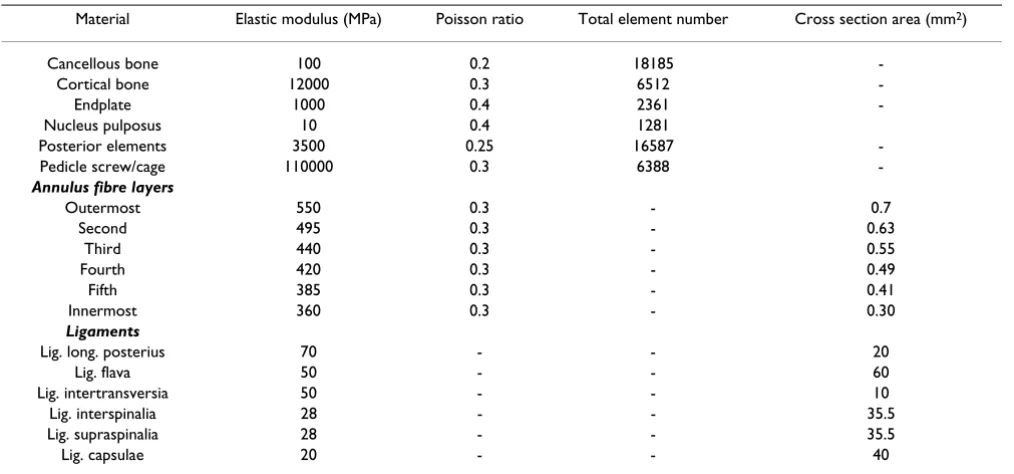
infe-Table 1: Material properties specified in the finite element models
Material Elastic modulus (MPa) Poisson ratio Total element number Cross section area (mm2)
Cancellous bone 100 0.2 18185
-Cortical bone 12000 0.3 6512
-Endplate 1000 0.4 2361
-Nucleus pulposus 10 0.4 1281
Posterior elements 3500 0.25 16587
-Pedicle screw/cage 110000 0.3 6388
-Annulus fibre layers
Outermost 550 0.3 - 0.7
Second 495 0.3 - 0.63
Third 440 0.3 - 0.55
Fourth 420 0.3 - 0.49
Fifth 385 0.3 - 0.41
Innermost 360 0.3 - 0.30
Ligaments
Lig. long. posterius 70 - - 20
Lig. flava 50 - - 60
Lig. intertransversia 50 - - 10
Lig. interspinalia 28 - - 35.5
Lig. supraspinalia 28 - - 35.5
[image:3.612.54.561.99.336.2]rior surface of L5 was constrained in all direction. The selection of these loads simulated situations in an in vitro experimental study, allowing for validation FEA output of an intact spine model [8,10,21,22]. The commercially available FEA software MARC (MSC Software Corp., Los Angels, USA) was used for these analyses. Analyses were performed using the computing facilities at the National Center for High-Performance Computing (NCHC, Hsin-Chu, Taiwan) via internet connection. Analysis results were retrieved back and processed on a local personal computer. All analysis results for the models with inter-body spacers were compared with those of the intact one.
Results
Convergences of FEM
The convergences of the FEMs were justified by the total strain energy of the structures. Four models with different numbers of elements and nodes were created to perform the convergence test, and the results of the total strain
energy for the four models were all within 5% difference. In this study, the model with the finest mesh was used and the convergence of the FEMs was demonstrated from the above procedures.
Validation of the intact FEM
We validated the intact FEM by comparing the flexion and extension angles with those of previously published experimental studies [23,24]. The previous studies had indicated that the flexion and the extension angles ranged between 5° – 6.2° and 2.8° – 4.2°, respectively, under a 10 N-m flexion or extension moment. In current study, the flexion angle was 5.4° under a 10 N-m flexion moment, and the extension angle was 3.1° under a 10 N-m extension N-moN-ment. These data were closely correlated with the results of past studies (Figure 2a).
[image:4.612.54.557.88.439.2]Finite element models of three interbody cages: (a) dual paralleled cage; (b) single large cage; (c) two-part cage, and (d, e, f) each inserted in the L4–L5 motion segment supplemented with posterior instrumentations
Figure 1
Validation of the FEM with cage insertion
Initially, our FEM with dual-paralleled cage insertion was validated by comparing the rotational angle of vertebrae with those reported using Tsantrizos, experimental setup, which applied the following moments: (1) 4.0 N-m flex-ion-extension moment; (2) 4.0 N-m axial rotation moment; (3) 8.0 N-m lateral bending moment. All load-ing conditions were applied with a 200 N preload (Figure 2b) [25]. In addition, we found that the relative micromo-tion at the implant-bone interface increased with the increasing compression force (150N–600N), and with the decreasing friction coefficient (0.4–0.2) [19]. All the cal-culated data were consistent with the in vitro experimen-tal reports.
Stresses of interbody cages on vertebral endplates
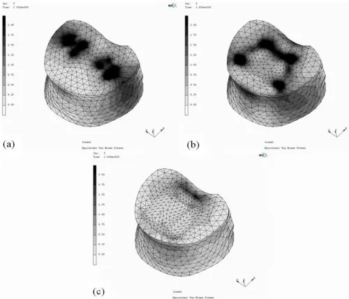
To simplify the analytic procedures, identical cancellous bone density of 100 MPa was defined in our study to eval-uate the peak stress of the selected cages designs on the vertebral endplate. With the consistent lordotic angle and maximal contact of the cage-bone interface, the peak stress of the DPC was mapped on the whole contact area of the endplate, the SLC on the periphery of posterior interface, and the TPC on the central edge of posterior interface (Figure 3). The cage insertions, with different designs, illustrated significantly different peak stress dis-tribution on the cage-bone interface. Examples for the per-centile differences of the maximum von Mises stress on the L5 superior endplate were calculated as (σDPC-σTPC)/
σDPC or (σSLC-σTPC)σSLC. The maximum stress of the end-plate after the TPC insertion decreased by 60% and 23%
as compared with that after the DPC and SLC insertion, respectively.
Facet contact stresses after interbody cages insertion
Under flexion-extension, lateral bending and torsion (10 N-m moment loading) conditions, the facet contact stress values in the FEM with cage insertion were calculated (Fig-ure 4a). The predicted facet stress values under extension, lateral bending and torsion loadings were larger than those under flexion in all cage groups. Besides, the pre-dicted facet stress values after DPC and SLC insertion were larger than those after TPC insertion. When supplemented with posterior pedicle screw fixation, most of the facet stress was shared by the supplemented implants. The stress values on the screws were comparable among the intact, DPC, SLC and TPC groups under flexion and exten-sion loadings (Figure 4b). On the other hand, under lat-eral bending and torsion, the stress values on the screw of DPC, SLC and TPC groups were larger than the intact group.
Slip distance of the implant-bone interface after interbody cage insertion
Relative micromotion on the implant-bone interface was noted at the peripheral edges under axial compression, which increased with the addition of flexion, extension, lateral bending and torsion moments to the compressive preload [19]. In our study, with the setting of determined cancellous bone density, loading force, and friction coef-ficient of 0.4, the slip displacement values on the cage-bone interface were calculated in various loading
condi-(a) Validation of our intact finite element model, as compared with Markolf, Schultz, Tencer, Shirazi-Adl et al studies; (b) Vali-dation of our finite element model with dual paralleled cage insertion, as compared with Tsantrizos et al. experimental study Figure 2
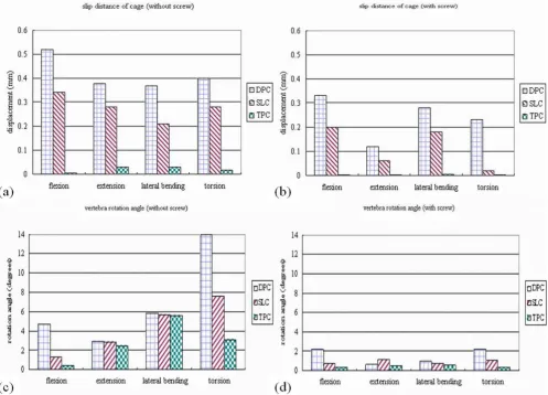
tions. Under each loading condition, the predicted dis-placement values after TPC insertion were smaller than those after DPC and SLC insertion (Figure 5a). When sup-plemented with posterior fixation, the displacement val-ues decreased by 25–40% under flexion, lateral bending and torsion loadings and decreased by 70% under exten-sion among the DPC and SLC groups. In TPC group with posterior fixation, the predicted displacement value decreased to zero level under all loading conditions (Fig-ure 5b). Most likely, there was no significant effect of pos-terior fixation upon the slip behavior of TPC insertion group.
Rotational angle of the upper vertebra after interbody cage insertion
With the consistent segmental lordosis and maximal con-tact of the cage-bone interface, the rotational angle of the upper vertebra was calculated, as compared to the intact model, under various loading conditions. Under flexion and torsion loading conditions, the predicted rotational angles after the TPC insertion were smaller than those after the DPC and SLC insertion (Figure 5c). However, there was no difference in rotational angle under lateral bending and extension, which might be attributed to the threaded cylinder incorporated in the TPC group. The threaded cylinder had no prominent effect on lateral
[image:6.612.54.554.87.515.2]The maximum von Mises stress distribution on the L5 upper endplate after insertion of various interbody cages: (a) dual paral-leled cage; (b) single large cage; (c) two-part cage
Figure 3
bending and extension moments. When supplemented with posterior fixation, the rotational angle decreased by 80–90% under lateral bending and decreased by 60–80% under extension among the DPC, SLC and TPC groups (Figure 5d). Results were similar in all cage groups with or without supplementary posterior fixation under lateral bending and extension in spite of cage designs.
Discussion
The introduction of interbody cages for spinal fusion has been a promising innovation; nevertheless, there is ongo-ing debate regardongo-ing the necessary conditions for success-ful fusion [1,4]. The influence of implant designs, surgical approach, additional posterior instrumentation and bone mineral density on stiffness, compressive strength and three-dimensional flexibility of the spinal units under static and cyclic loading have been investigated [2,5,7,11,13]. This study used FEA to investigate the inter-face mechanics and deformation levels in a range of vari-ous loading conditions among three trapezoid cage systems. In our FEMs with cage insertion, similar to that of Kim's report [19], micromotion at the cage-bone inter-face increased with applied load and was sensitive to the friction coefficient. Additionally, the parameters of facet contact stress, cage stress on the endplate and rotational angle of the upper vertebra were evaluated under different loading conditions in this study. In the event of physio-logical loading and maximal contact on the cage-bone interface, a stand-alone two-part fusion cage model has minimal slip displacement and rotational angle under compression, flexion, extension, lateral bending and tor-sion, as compared with the traditional cages, even with the additional posterior fixation. Conceptually, the adja-cent vertebrae with sufficient density in the peripheral
regions tolerate the above alteration following cage inser-tion, and an adequate remodeling for fusion is subse-quently achieved.
Relative micromotion on the cage-bone interface can hinder bone growth into the surface pores of an interbody cage and eventually induce endplate failures with cage subsidence [9,10,12,18]. Interface mechanics provides insight and interpolation for the observed performance of established fixations and a point of departure for design improvements. A FEA study is an appropriate tool for such a purpose, allowing us to repeat experiments, change parameters, and analyze the effect of a single component within the designed constructs [9,10,19]. In the current FEMs with cage insertion under coupled loadings, com-plete contact on the cage-bone interfaces was assumed; therefore, the computed slip behaviors would be underes-timated to avoid local bone failure from stress concentra-tion. In addition, the slip distance of the cage-bone interface and the rotational angle of the upper vertebra were non-uniform, because of compressive indentation induced by body weight. The quantified amount of slip distance and rotational angle in the current two-part cage models is a critical advantage for the varying characteris-tics of traditional interbody spacers. Biomechanical bene-fit of the stand-alone two-part cage is justifiable in this study. Under flexion or torsion with a preload on the lor-dotic lumbar spine, the slip distance of the cages and rota-tional angle of the vertebrae measured at the anterior contact edges were smallest in the two-part cage group. However, under lateral bending or extension with a preload, there was no difference in the rotational angle among all cage models. Theoretically, the threaded cylin-der incorporated in the trapezoid box had no prominent
(a) Facet contact stresses values before and after interbody cages insertion; (b) Supplemented screw stresses values, sepa-rately, before and after interbody cages insertion
Figure 4
effect on the lateral bending and extension moments. A design modification of stand-alone cages using the diver-gent orientation of vertebral fixation incorporated in the box had been considered to overcome lateral bending and extension loadings [26]. However, as compressive load increased, improvement in the cage-bone contact and bone density of the adjacent vertebrae would overcome excessive cage micromotion on the endplate and lead to cage stabilization. Furthermore, age-related changes in the mechanical properties of the annulus fibers and vertebrae would reduce the stability of interbody spacers on a spinal segment, increasing cage stress on the interfaces under var-ious combined loadings. This high stress might result in early failure of the endplate. Therefore, the stand-alone anterior two-part cage would not be indicated in the oste-oporotic spine.
The results of FEA, as calculated by a mathematical method, should be interpreted as a trend only. This study has several limitations. First, inter-individual variation of bone geometry and material properties does not exactly reflect the behavior of all the human specimens tested. Major differences may occur, and validation of the results in an in vitro and in vivo study is recommended. Second, the bone-implant interface can be described as only an approximation to in vitro or in vivo conditions. It is unclear how the packed bone graft chips are connected to the host vertebrae. We have chosen to simulate the inser-tion of a solid spacer into the middle part of the disc space and do not think that this discrepancy from the in vitro model influenced our findings: the compressive load was mainly transferred through the peripheral part of the cages, not through the central part of the bone graft. Third, the interbody spacer was juxtaposed on an arbitrary shape/volume in the cancellous core of L4 and L5
[image:8.612.57.554.89.446.2]verte-Slip distance of the implant-bone interface after interbody cages insertion: (a) without pedicle screw supplementation; (b) with pedicle screw supplementation
Figure 5
bral body. We have assumed an ideal situation for graft incorporation without taking into account some factors: the effect of topology, stress at the graft/host bone inter-face, and local blood supply. Fourth, an extensive valida-tion has not been done by comparing the predicvalida-tion of several cage FEMs to a corresponding part of the experi-mental study, or by analyzing bone density to more pre-cisely determined value of the osteoporotic level. We think that the influence of bone density on the compres-sive stiffness of cage FEA has been defined. The current FEA only predicts the relative movement of the segments under different loading conditions. For example, graft resorption, settling or partial implant failure may occur, resulting in a decrease of initial stability and the need for additional posterior instrumentation following cage insertion. Fifth, a fully bonded pedicle screw fixation was assumed on the posterior elements, which neglected the relaxation effect of the posterior implant on the coupling of load share after the solid arthrodesis. Finally, we have chosen to generate a L4–L5 model with material proper-ties equivalent to those reported by Goel et al. [14,27,28]. Using experimental data from L2-3 and L3-4 human seg-ments to validate a L4-5 model clearly is a limitation of the present study. However, with the consistent segmental lordosis and maximal contact of the cage-bone interface, it has been shown that both anatomical details and seg-mental flexibility are quite similar in human lumbar spine segments for L2-3, L3-4 or L4-5.
Conclusion
In conclusion, the current study investigated the effects of geometric properties, loading conditions and cage-bone interface mechanics on the characteristics of several inter-body cages. The biomechanical benefit of a stand-alone two-part cage is promising in spinal surgery to avoid sur-gical morbidities in damaged posterior muscles and facet joints caused by posterior instrumentation. This device addresses the stability required for interbody fusion, and supports the necessity of clinical trials using this alterna-tive to the circumferential fixations. However, in the oste-oporotic spine, supplementation with posterior fixation is recommended under various loading conditions.
Competing interests
The authors declare that they have no competing interests.
Authors' contributions
S–HC participated in the study design, in collecting the data, the statistically analyses and drafting of the manu-script. C–LT, C–YL and P–HH participated in the study design. W–PC advised and assisted drafting of the script. All authors read and approved the final manu-script.
Acknowledgements
This study was supported by a grant from the National Science Council of the Republic of China. The computing facilities provided by the National Center for High-Performance Computing are greatly appreciated.
References
1. Pavlov PW, Spruit M, Havinga M, Anderson PG, van Limbeek J, Jacobs WC: Anterior lumbar interbody fusion with threaded fusion cages and autologous bone grafts. Eur Spine J 2000,
9(3):224-229.
2. Oxland TR, Lund T: Biomechanics of stand-alone cages and cages in combination with posterior fixation: a literature review. Eur Spine J 2000, 9:S95-S101.
3. Brantigan JW, Steffee AD, Lewis ML, Quinn LM, Persenaire JM: Lum-bar interbody fusion using the Brantigan I/F cage for poste-rior lumbar interbody fusion and the variable pedicle screw placement system: two-year results from a Food and Drug Administration investigational device exemption clinical trial. Spine 2000, 25(11):1437-1446.
4. Kuslich SD, Danielson G, Dowdle JD, Sherman J, Fredrickson B, Yuan H, Griffith SL: Four-year follow-up results of lumbar spine arthrodesis using the Bagby and Kuslich lumbar fusion cage.
Spine 2000, 25(20):2656-2662.
5. Steffen T, Tsantrizos A, Aebi M: Effect of implant design and end-plate preparation on the compressive strength of interbody fusion constructs. Spine 2000, 25(9):1077-1084.
6. Oxland TR, Lund T, Jost B, Cripton P, Lippuner K, Jaeger P, Nolte LP:
The relative importance of vertebral bone density and disc degeneration in spinal flexibility and interbody implant per-formance. Spine 1996, 21(22):2558-2569.
7. Steffen T, Tsantrizos A, Fruth I: Cage: designs and concepts. Eur Spine J 2000, 9:S89-S94.
8. Kettler A, Wilke HJ, Dietl R, Krammer M, Lumenta C, Claes L: Sta-bilizing effect of posterior lumbar interbody fusion cages before and after cyclic loading. J Neurosurg 2000, 92:87-92. 9. Overaker DW, Langrana NA, Cuitino AM: Finite element analysis
of vertebral body mechanics with nonlinear microstructural model for the trabecular core. J Biomech Eng 1999,
121(5):542-550.
10. Polikeit A, Ferguson SJ, Nolte LP, Orr TE: Factors influencing stresses in the lumbar spine after the insertion of interverte-bral cages: finite element analysis. Eur Spine J 2003,
12(4):413-420.
11. Boden S, Sumner D: Biologic factors affecting spinal fusion and bone regeneration. Spine 1995, 20:102S-112S.
12. Silva MJ, Keaveny TM, Hayes WC: Load sharing between the shell and centrum in the lumbar vertebral body. Spine 1997,
22(2):140-150.
13. Grant JP, Oxland TR, Dvorak MF: Mapping the structural prop-erties of the lumbosacral vertebral endplates. Spine 2001,
26(8):889-896.
14. Yamamoto I, Panjabi MM, Crisco T: Three-dimensional move-ments of the whole lumbar spine and lumbosacral joint. Spine
1989, 14(11):1256-1260.
15. Rohlmann A, Zander T, Bergmann G: Comparison of the biome-chanical effects of posterior and anterior spine-stabilizing implants. Eur Spine J 2005, 14(5):445-53.
16. Shirazi-Adl SA, Shrivastava SC, Ahmed AM: Stress analysis of the lumbar disc-body unit in compression. A three-dimensional nonlinear finite element study. Spine 1984, 9(2):120-34. 17. Smit T, Ddgaard A, Schneider E: Structure and function of
verte-bral trabecular bone. Spine 1997, 22(24):2823-2833.
18. Lu YM, Hutton WC, Gharpuray VM: Do bending, twisting, and diurnal fluid changes in the disc affect the propensity to pro-lapse? A viscoelastic finite elements model. Spine 1996,
21(22):2570-2579.
19. Kim Y: Prediction of mechanical behaviors at interfaces between bone and two interbody cages of lumbar spine seg-ments. Spine 2001, 26(13):1437-1442.
20. Chen CS, Cheng CK, Liu CL, Lo WH: Stress analysis of the disc adjacent to interbody fusion in lumbar spine. Med Eng Phys
2001, 23(7):483-491.
Publish with BioMed Central and every scientist can read your work free of charge "BioMed Central will be the most significant development for disseminating the results of biomedical researc h in our lifetime."
Sir Paul Nurse, Cancer Research UK
Your research papers will be:
available free of charge to the entire biomedical community
peer reviewed and published immediately upon acceptance
cited in PubMed and archived on PubMed Central
yours — you keep the copyright
Submit your manuscript here:
http://www.biomedcentral.com/info/publishing_adv.asp
BioMedcentral
22. Skalli W, Robin S, Lavaste F, Dubousset J: A biomechanical analy-sis of short segment spinal fixation using a three-dimensional geometric and mechanical model. Spine 1993, 18(5):536-545. 23. Tencer AF, Ahmed AM, Burke DL: Some static mechanical
prop-erties of the lumbar intervertebral joint, intact and injured.
J Biomech Eng 1982, 104(3):193-201.
24. Shirazi-Adl A, Ahmed AM, Shrivastava SC: Mechanical response of a lumbar motion segment in axial torque alone and com-bined with compression. Spine 1986, 11(9):914-927.
25. Tsantrizos A, Baramki HG, Zeidman S, Steffen T: Segmental stabil-ity and compressive strength of posterior lumbar interbody fusion implants. Spine 2000, 25(15):1899-1907.
26. Cain CM, Schleicher P, Gerlach R, Pflugmacher R, Scholz M, Kandzi-ora F: A new stand-alone anterior lumbar interbody fusion device: biomechanical comparison with established fixation techniques. Spine 2005, 30(23):2631-2636.
27. Goel VK, Kong W, Han JS, Weinstein JN, Gilbertson LG: A com-bined finite element and optimization investigation of lum-bar spine mechanics with and without muscles. Spine 1993,
18(11):1531-1541.
28. Skalli W, Robin S, Lavaste F, Dubousset J: A biomechanical analy-sis of short segment spinal fixation using a three-dimensional geometric and mechanical model. Spine 1993, 18(5):536-545.
Pre-publication history
The pre-publication history for this paper can be accessed here: