2019 International Conference on Computer Science, Communications and Multimedia Engineering (CSCME 2019) ISBN: 978-1-60595-650-3
Acquisition Algorithm of Spatial Control Parameter Tilt Angle for
On-line Insulator
Chen-hong YAO
*and Xi-zhen ZHANG
Xi’an University of Architecture & Technology, Xi’an, China
*Corresponding author
Keywords: Insulator Robot, Insulator Spatial Control Parameter, Tilt Angle.
Abstract. Most vision control of the existing power-line insulator robot system needs to be realized indirectly through the remote computer. The vision system itself does not have the ability of vision control, and the level of automation is low. In order to improve the visual control ability and automation level of the power-line insulator robot, an on-line spatial control parameter acquisition algorithm for insulator is presented based on target extraction. The algorithm can be embedded in the hardware platform of visual system to automatically measure tilt angle of insulators. The results of hardware implementation show that the proposed algorithm can measure tilt angle parameters relatively accurately on the hardware platform of visual system. The error of tilt angle measurement is 0.4°~4°, which achieves the desired effect and design requirements.
Introduction
Through the research of transmission line robots at home and abroad in recent years, it is found that most of the research focuses on mechanical control system, manipulator and obstacle climbing. In the control of transmission line robot, the robot vision system can only collect line insulator images and transmit them to the ground base station through wireless devices, and then send control signals to remote control the robot for on-line insulator maintenance after image data processing by artificial ground control computer [1-5]. Therefore, the existing robot vision system itself does not have visual control ability, and cannot get rid of manual intervention to complete the task. In addition, binocular ranging, which is often used in visual ranging, has high measurement accuracy, but its algorithm is complex, its operation time is long, its feature matching is difficult and its working environment is strict[6]. And monocular vision ranging has simple structure, high universality and low cost [7], which is more suitable for the realization of microcontroller in vision system with low main frequency.
In order to improve the visual control ability and automation level of insulator operating robot for transmission line, a hardware-based algorithm for acquiring spatial control parameters of insulator is presented in this paper based on the principle of keyhole imaging and the hardware platform of vision system. The algorithm can be applied to the embedded hardware platform of vision system to measure tilt angle of insulators online. In order to obtain angle parameters, it is necessary to analyze the imaging status of insulators in visual sensors based on the completion of insulator target extraction. And then, the geometric model and coordinate reference system of distance measurement are established by using the position relationship between the insulator target center and the visual sensor. Finally, after finding the corresponding relationship according to the above conditions, the tilt angle of insulators are measured and calculated, and the algorithm is verified by hardware implementation.
Algorithmic Principle
modes of insulators on transmission lines can be basically summarized into three types: vertical suspension, inclined suspension and horizontal suspension.
The actual acquired insulator target image changes with the distance between the robot and the insulator, and characteristics of the insulator target in the image space will also change. The image space characteristic parameters measured from the extracted insulator target images mainly include the central axis length of insulator string, the long axis of insulator umbrella lobe and the short axis of insulator umbrella lobe.
In Figure 1, the red horizontal dotted line represents the long axis of the insulator umbrella lobe, while the black vertical dotted line represents the short axis of the insulator umbrella lobe. The shorter the distance between the visual sensor and the insulator is, the fewer insulator umbrella lobes will enter the image in vertical mode and inclined mode. The length of the central axis of insulator string is not fixed in the two observation maps, and the measurement of the short axis length of insulator umbrella lobes in the oblique insulator target map is slightly complicated. Only the long axis of insulator umbrella lobe still exists in these two observation maps along with the change of relative distance and is easy to measure and calculate; in the horizontal insulator target observation map, the insulator target presents a quasi-circular state, and the closer the relative distance is, the larger the circle is in the observation map. In this type of observation map, the central axis of insulator string and the short axis of umbrella lobe cannot be measured, only the long axis of insulator umbrella lobe is fixed and can be measured. Therefore, the long axis of the insulator umbrella lobe fixed in the three types of insulator target observation maps with the change of relative distance is chosen as characteristic parameter in the image space to measure.
Figure 1. Insulator single umbrella lobe diagram.
Since the insulator image pixel reading mode is from left to right and from top to bottom, the origin is located in the upper left corner of the image, and a two-dimensional pixel coordinate system oxy is established on the physical imaging plane. The coordinates of the pixels in the image plane are (x, y). The calculation of image space characteristic parameter size l (image size l) is based on the two-dimensional pixel coordinate system.
In order to measure the size of insulator umbrella lobe long axis image l, the minimum outer rectangle of insulator target image is introduced. The minimum outer rectangle of an image is minimum rectangle range framing the target with four two-dimensional coordinate points. The rectangle drawing is completed by four vertices, i.e. the maximum and minimum abscissa and ordinate coordinates of the image object. The minimum outer rectangular pixel coordinates of insulator target images in three modes are shown in Figure 2.
y
x
o x2
y2
y1
m1
x1
m2
m3 m4
x
y
o x1 x2
y1
y2
m1 m2
m3
m4
y2
x
y y1
x1 x2
o
m1 m2
m3 m4
[image:2.595.125.469.616.728.2](a) Vertical mode (b) Inclined mode (c) Horizontal mode
Figure 2. A schematic diagram of pixel coordinates for the minimum outer rectangle.
The process of obtaining the coordinates four vertices m1, m2, m3 and m4 is divided into three
Step 1: Traverse every pixel on the binary insulator target image from left to right from top to bottom to determine whether the pixel is the target point, i.e. black point (0xFFFF). If it is black point, the row and column coordinates of the black point are stored in one-dimensional arrays R and
C, respectively, until the coordinates of the whole target point are stored.
Step 2: Find the maximum and minimum values of the members of the one-dimensional array R
and C, i.e. the maximum x2 and the minimum x1 of row coordinates, the maximum y2 and the
minimum y1 of column coordinates, respectively, and store them in the pre-defined array RC, where
RC={ x2, x1, y2, y1}.
Step 3: According to the maximum and minimum values of row and column coordinates, the four vertex coordinates m1(x1, y1), m2(x2, y1), m3(x1, y2) and m4(x2, y2) of the smallest outer rectangle can
be obtained.
When the robot moves into a safe distance, in order to facilitate the robot to work on the insulator, it is necessary to determine the tilt angle of the insulator relative to the conductor in the inclined state, which is used as the reference data for the robot to grasp the insulator. The process of measuring the tilt angle of insulator is shown in Figure 3.
Calculation for image size ratio q
Calculation for inclined radian R Binary insulator
target image Relational expression between R and q angle ɤ
Figure 3. Process of measuring the Tilt Angle of insulator.
According to a large number of hardware experiments, it is found that there is always a fixed and measurable ratio between the inclined radian and the image size ratio q for a certain type of insulator. As long as the size ratio q of the insulator target image is obtained, the inclined radian can be obtained by the pre-determined proportional relation, and then the inclined radian can be converted into the inclined angle.
In Figure 4, the tilt angle ɤ is to be calculated. n1, n2, n3 and n4 are the four vertices of the inclined
insulator target image. The coordinates are (x2, y1), (x3, y1), (x1, y2) and (x4,y2), respectively. Although
the target image of tilted insulator increases with the movement of the robot, the ratio q of the target image size n1n2 to n3n4 will remain unchanged as long as the degree of tilt angle of insulator is
constant. If the tilt angle changes, the target image size ratio q of insulator changes accordingly. The simplified formula for q is
3 2
3 21 2
3 4 4 1 4 1
x x w x x n n
q
n n x x w x x
(1)
Where w is the pixel size, x1, x2, x3 and x4 are the abscissa coordinates of the four vertices. The
calculation includes two steps.
ɤ
x
y
o x1 x3
y1
y2
n1 n2
n3 n
4
x2 x4
[image:3.595.144.457.577.705.2](a) Schematic diagram (b) Pixel coordinate of insulator tilt angle system
Figure 4. Principle diagram for calculating inclined radian of insulator.
Step 2: Specify column coordinates y2 and y1, and traverse the image from left to right until the
corresponding abscissa of the pixel point is black, that is, to get x2 and x3,x1 and x4. After calculating
x2 and x3, x1 and x4, the image size ratio q of insulators can be obtained according to (1).
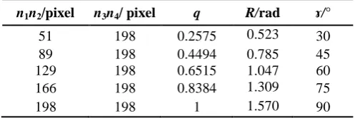
[image:4.595.195.406.191.331.2]In this paper, a silica gel insulator is used as the target insulator. The relationship between the inclined radian R and the image size ratio q of the target insulator under the ideal extraction condition is obtained by calculation in advance as shown in Table 1. The least square method is used for linear approximation fitting. The actual curve and the fitting straight line are drawn as shown in Figure 5.
Figure 5. Folded Line Diagram for Relationship of R VS q.
Table 1. Tilt Angle Relations of Silicone Insulators in Ideal State.
n1n2/pixel n3n4/ pixel q R/rad ɤ/°
51 198 0.2575 0.523 30
89 198 0.4494 0.785 45
129 198 0.6515 1.047 60
166 198 0.8384 1.309 75
198 198 1 1.570 90
In Figure 5, the relationship between the inclined radian R of insulator and the image size ratio q
shows a rising line after fitting approximation by least square method. The linear relationship after fitting is
1.3954 0.15463
R q (2)
The target image size ratio q of the silica gel insulator need be obtained by image processing algorithm, and the inclined radian can be calculated by (2), which will be converted into inclined angle of the insulator then.
Hardware Platform
[image:4.595.173.422.386.469.2]
(a) Insulator Tilt (b) LCD Display of Angle Test Live Diagram Vision System
Figure 6. Hardware Platform of Vision System for Transmission Line Insulator Operating Robot.
Experiment Results
The algorithm is tested on the embedded platform of vision system. The experiment mainly carries out the software test of the visual control function of the robot vision system under the vertical and inclined state of insulators. The observation direction of the robot vision sensor with insulators is in vertical and inclined states.
Functional test of insulator space control parameters acquisition includes measurement of calculation of tilt angle. The hardware test of tilt angle is to change the Tilt angle of insulator when the relative distance is fixed.
Insulator target spans the whole column coordinates in the whole image, only the size of the largest umbrella lobe long axis image of the insulator in the image needs to be calculated. In order to reduce the amount of calculation and improve the timeliness of the algorithm, the calculation of the smallest outer rectangle does not traverse the pixels in the whole binary image [800,480], and the traversal range of column coordinates in the hardware experiment is [20, 460], the traversal range of row coordinates is [20,780]. Spatial control parameter acquisition function experiment takes silica gel insulator as the measurement target.
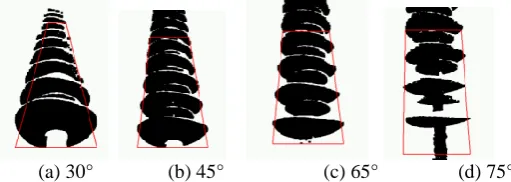
[image:5.595.146.425.70.167.2]Insulator tilt angles are measured with four oblique angles of 30°, 45°, 65°and 75°, respectively, at a vertical observation angle of 40 cm away from the insulator. The experimental results are shown in Figure 7.
[image:5.595.174.430.467.558.2]
(a) 30° (b) 45° (c) 65° (d) 75°
Figure 7. Experimental Diagram to Measure Tilt Angle.
The shape of the image is more similar to that of a triangle as the tilt angle of the insulator decreases. The visual system calculates the tilt angle according to the size ratio q and Formula (2) of insulator target image. The results are shown in Table 2.
Table 2. Hardware Measurement of Insulator Tilt Angle.
Group number
Actual angle
/°
Actual radian /rad
Measurement image size ratio
Measurement radian /rad
Measurement angle /°
Error /°
1 30 0.523 0.23 0.48 27.5 2.5
2 45 0.785 0.41 0.73 41.8 3.2
3 65 1.134 0.68 1.11 63.6 1.4
Conclusion
On the basis of the hardware platform of the vision system of insulator-operated robot, the position relationship between the insulator target center and the vision sensor is analyzed, the geometric model of distance measurement and the coordinate reference system are established, and an on-line algorithm for acquiring spatial control parameters of insulator is presented. The algorithm does not need the ground base station computer to process image, and can be directly embedded into the hardware platform of the visual system to complete image processing to obtain tilt angle parameters. The experimental results show that the error range of angle measurement is 0.4° ~4° in 75° tilt angle, which achieves the expected effect and design requirements. The implantation of the algorithm not only enhances the visual control ability of the robot vision system, but also improves the level of automation of the robot operation.
Acknowledgment
The paper is supported by General Project of Shaanxi Provincial Science and Technology Department (2017GY-015).
References
[1] Liu Guohai, Zhu Zhu. Application of image processing technology in vision system of ultra-high pressure inspection robot [J]. Computer Engineering and Design, 2009, 30 (1): 136-140.
[2] Zhu Yanhuan. Research on Visual Detection Method for Line-Patrolling Robot [D]. Harbin University of Technology, 2017.
[3] State Grid Corporation, Baishan Power Supply Company, Jilin Province Power Co., Ltd. State Grid Corporation. Robot System for Patrolling Transmission Lines Crossing Forest Areas: China, CN201310640634.9 [P]. 2015-06-10.
[4] Li Xiaoxu, Zhou Huanyin. Design of Visual Control Navigation for Smart Car Based on STM32 [J]. Electronic Design Engineering, 2017, 25 (9): 105-107, 112.
[5] Liu Tianlin, Yang Boyu, Pan Guangzhen. Target extraction and processing system based on STM32 [J]. Journal of Testing Technology, 2017, 31 (2): 144-147.
[6] Wang Zhongliang, Wu Gongping, He Yuan, et al. Research on obstacle location of HV transmission line based on monocular machine vision [J]. Mechanical design and manufacturing, 2015, (4): 85-87.