International Journal of Emerging Technology and Advanced Engineering
Website: www.ijetae.com (ISSN 2250-2459, ISO 9001:2008 Certified Journal, Volume 2, Issue 12, December 2012)
354
Performance Improvement of a Regenerative Gas Turbine
Cycle Through Integrated Inlet Air Evaporative Cooling
and Steam Injection
Shyam Agarwal
1, S.S. Kachhwaha
2, R.S. Mishra
31,3Department of Mechanical Engineering, Delhi Technological University, Bawana Road, Delhi-110042,
2
Pandit Deendayal Petroleum University, Gujrat, India.
Abstract
-
Like many developed countries, energyefficiency and environment impact are the most important process in the development of power generation policy in India. A high ambient temperature reduces the air density and makes inlet air cooling (IAC) and steam injection gas turbine (STIG) attractive power augmentation method for existing regenerative gas turbine. With a high back work ratio and a high exhaust temperature, the regenerative cycle gas turbine generation system usually has low generation efficiency particularly in hot ambient weather conditions. From available retrofitting technologies to improve the power generation capacity and efficiency of regenerative cycle gas turbine, IAC through fog cooling and STIG are considered most effective ways to modify an existing simple cycle unit without major description to its original integrity. To evaluate and stimulate the performance of power generation system, a computer program has been developed. The results from computer simulation indicated that the retrofitting of regenerative cycle with IAC and STIG can boost the power output from 30MW to 49.05MW while the generation efficiency can be increased from about 36.99% to 45.21%. The effect of retrofitting techniques on exergy destruction in various system components has also been determined. The exergy destruction rate per MW of power output for different system components (combustion chamber and compressor) reduces while for gas turbine increases for retrofitted cycles.
Keywords- Regenerative gas turbine; Retrofitting, Inlet
air cooling, STIG, Exergy destruction
I. INTRODUCTION
Regenerative gas turbine power generation system are most common powere generation units in entire world. A large number of power generation units in Indaia use regenrative gas turbine in order to utilize the heat energy of exhaust gases from the turbine. Rgenerative units are more efficient and benefitial compare to simple cycle units to fulfill the peak load demand but provide low power output and overall efficiency during summer season. In order to recover lost power output and overall efficiency, the retrofitting techniques have seriously been considered by which increasing demand of electricity can be fulfilled.
The thermodynamic analysis of regenerative gas turbine power generation system results that huge amount of useful energy has wasted along with exhuast gases
(which release out from the turbine about at 400 0C to
500 0C). However, some amount of heat energy of
exhaust gases have been recoverted into the regenerator yet a large amount of heat goes wasted in to the atmosphere along with exhuast gases after regenerator means there is a considerable amount of heat energy remains present into the exhaust gases which has to be recovered in order to make the cycle efficient. Secondly, a large part of turbine work has used to compress the inlet air.
Many well established technologies can be used to enhance the power output and thermal efficiency of the regerative gas turbine. Among those, single or double effect vapour absorption LiBr refrigeration system, spray cooling system may be employed to cool the inlet air to the compressor by which the compressor work-done can be reduced. Along with above mentioned inlet air cooling techniques (IAC) the steam injection gas turbine (STIG) technology may also employed to recover the available energy of exhaust gases . The integration of IAC and STIG technologies can be employed with regenerative gas turbine cycle in order to boost power out and generation efficiency of the power generation unit which consequences the most effective way to use retrofitted techniques.
International Journal of Emerging Technology and Advanced Engineering
Website: www.ijetae.com (ISSN 2250-2459, ISO 9001:2008 Certified Journal, Volume 2, Issue 12, December 2012)
355
The high pressure steam generated into the heat recovery steam generator (HRSG) has also fed into the combustion chamber in the form of STIG. The injection ratio of the steam has to be maintained according to the manufacture prescribed for the combustion chamber and turbine.
Nishida et al.1 have analyzed the performance
characteristics of two configuration of regenerative steam-injection gas turbine (RSTIG) systems. They concluded that the thermal efficiencies of the RSTIG systems are higher than those of regenerative, water
injected and STIG systems. . Hawaj & Mutairi2 studied a
cogeneration system comprising a combined cycle power plant (CCPP) with an absorption chiller used for space cooling. They have also studied the relative advantage of using CCPP with absorption cooling over thermally equivalent mechanical vapor compression (MVC).They found that a cogeneration CCPP with absorption cooling yields significantly less power penalty than a CCPP with
a MVC cooling. Pelster et al.3 studied the combined cycle
with advanced options viz. compressor air inter-cooling,
water injection and reheating. They studied
environmental and economic analysis simultaneously. They have optimized the system for economic and other
better operations. Bhargava & Homji4 have studied
parametric analysis of existing gas turbines with inlet
evaporative and overspray fogging. Chaker et al.5 have
presented fog droplet sizing analysis, nozzle types, measurement, and testing. The result of extensive experimental and theoretical studies conducted over several years includes coupled with practical aspects learned in the implementation of nearly 500 inlet fogging systems on gas turbines ranging in power from 5 to 250 MW. This study describes the different measurement techniques available, covers design aspects of nozzles, provides experimental data on different nozzles, and provides recommendations for a standardized nozzle
testing method for gas turbine inlet air fogging. Bansode6
have studied the effect of fog cooling system for inlet air cooling. They concluded that performance parameters indicative of inlet fogging effects have a definite correlation with the climate condition (humidity and temperature) and showed improvement in turbine power
and heat rate. Alexis7 has studied the performance
parameters for the design of a combined refrigeration and electrical power cogeneration system. A steam power cycle (Rankine) produces electrical power 2 MW and steam is bleeded off from the turbine at 7bar to warm a factor or units of buildings during winter or to supply a steam ejector refrigeration cycle to air-conditioning the
same area during the summer. Kumar et al.8 have been
developed design methodology for parametric study and thermodynamic performance evaluation of a gas turbine cogeneration system (CGTS).
Wang & Chiou9 suggested that application of IAC and
STIG technique can boost the output and generation efficiency. They concluded that implementing both STIG and IAC features cause more than a 70% boost in power
and 20.4 % improvement in heat rate. Bilgen et al.10has
developed design and economic methodology for the gas
turbine cogeneration system. Ondrays et al.11 have
investigated gas turbine power augmentation in a cogeneration plant using inlet air chilling. Gas turbine power augmentation in a cogeneration plant using inlet air chilling is investigated. Options include absorption chillers, mechanical (electrical driven) chillers, thermal energy storage, Motive energy for the chillers is steam from the gas turbine exhaust or electrical energy for mechanical chillers. Chilled water distribution in the inlet air system is described. The overall economics of the power augmentation benefits is investigated. They concluded that the gas turbine power augmentation via inlet air chilling can be effectively used to boost power during high ambient temperature usually synchronous with the on-peak power generation, allowing leveling of GT power output.
A large number of efforts have been executed to apply either STIG technology or the IAC method to enhance the gas turbine’s performance, to our knowledge, no attempt has been made to integrate these techniques in the combined form for the same system. In this study, a regenerative cycle generation unit is considered as base unit and STIG and IAC features are sequentially retrofitted to the system. The relative benefits obtained from either the STIG or IAC can be distinguished and the integrated efforts from the combined STIG and IAC can
be quantified for further economic analysis.
II. NOMENCLATURE
AP Approach point (0C)
PP Pinch point(0C)
TIT Turbine Inlet Temperature (K)
wbt Wet bulb temperature(0C)
M Molecular weight (kg/kmol)
E
Exergy rate (kW)U Internal energy (kJ)
m
Mass flow rate (kg/s) A. Subscriptssup superheated Th Thermal
HRSG Heat recovery steam generator GEN Heat generator
f fuel REG Regenerator
International Journal of Emerging Technology and Advanced Engineering
Website: www.ijetae.com (ISSN 2250-2459, ISO 9001:2008 Certified Journal, Volume 2, Issue 12, December 2012)
356
B. Superscript
fraction of gas phase at dead state
1 fraction of gas phase before combustion 2 fraction of gas phase after combustion
E
Exergy rate (kW)U Internal energy (kJ)
m
mass flow rate (kg/s) C. Greek symbolη efficiency λ fuel-air ratio ω steam-injection ratio
Exergetic efficiencyD. Acronyms and abbreviations
FCS Fog cooling system
STIG Steam injection gas turbine EVC Evaporative cooling
III. SYSTEM DESCRIPTION
The regenerative cycle gas turbine system integrated with both IAC and STIG featuring are shown in Figure 1.
The basic unit includes compressor, combustor, gas turbine and a generator. A heat recovery steam generator (HRSG) was installed at the downstream exit of the turbine (state point 5) in order to recover the heat from the exhaust gases. The fraction of superheated steam generated from the HRSG is used for STIG (state point 9) and the remaining steam is used for process application. An evaporative fog cooling system (FCS) is installed to
cool the ambient air (state point
1
) as shown in Fig. 1.Fog cooling is an active system which uses very fine droplets of high pressure water injected through special atomizing nozzles located at discrete points across the inlet duct at high pressure to create the cooling effect. The amount of fog is to be monitored based on dry and wet bulb ambient conditions to achieve the required cooling A typical fog cooling system consists of a high pressure pump skid connected for feeding to an array of manifolds located at a suitable place across the compressor inlet duct. The manifolds have a requisite
number of fog nozzles6 which inject very fine droplets of
water into the inlet air.
5
6
1’Ambient air Fog cooling
System
Water Compressor
2
Fuel f
4 Turbine
Steam-injection 9
8Condensate water water
7 Exhaust gases
Remaining superheated P steam 3
Air
Fogged and cooled air 1
Combustion products
Heat recovery steam generator
ω
(1-ω)
Fig. 1(a)- Regenerated cycle gas turbine with fog cooling and STIG
G
6
C. Ch.
[image:3.595.77.500.413.593.2]International Journal of Emerging Technology and Advanced Engineering
Website: www.ijetae.com (ISSN 2250-2459, ISO 9001:2008 Certified Journal, Volume 2, Issue 12, December 2012)
357
The discharge through each nozzle is around 3ml/s and produces 3 billion droplets per second. The fine fog evaporates very fast, thus dropping inlet air temperature.
IV. THERMODYNAMIC MODELING AND COMPUTER
SIMULATION
A.Formulation:
The following assumptions have been considered for the present study:
1.The composition of ambient air has been assumed
in terms of molar fraction of 1mole of air is:
N2=0.7748, O2=0.2059, CO2=0.00030 and
H2O=0.0190.
2.Fog cooling system has been maintained for 100%
saturation of ambient air at wet bulb temperature of air.
3.Fog cooling system has been maintained for 100%
saturation of ambient air at wet bulb temperature of air.
4.The pressure of water injected from the nozzle into
the evaporative cooling chamber has been assumed 138 bar and converts into the fog (fine droplets), absorbs latent heat of air through adiabatic mixing.
5.Combustion chamber has been maintained at
constant temperature.
6.The regenerator exchanges heat at constant pressure
with fixed effectiveness of 0.6118.
A computer program has been developed to formulate and simulate the retrofitting techniques over simple gas turbine with a set of steady-state governing equations including mass, energy, entropy and exergy balances
using control volume analysis sequentially for
compressor, combustor, gas turbine and HRSG.
A set of governing equations for a particular component (k) is expressed as-
Mass rate balance
(1)
Energy rate balance
(2)
Exergy rate balance
(3)
Where denotes the rate of exergy destruction and
denotes the associated exergy transfer rate due to heat
transfer.
If the effect of kinetic and potential energy is ignored,
the total exergy rate consisting of physical and
chemical can be expressed as
(4)
Superheater Evaporator Economizer
Heat
Recovered
Tem
p
.
Gas
Temperature
HRSG
Outlet
T
6
T
7 Tsu
p
Tcon
TECO
P
P
A
P
TDRUM
Fig. 1(b)- Temperature / Heat energy diagram for HRSG
im
i,k
em
e,k
cv,k e e,k e,k i i,k i,k k,
cv
W
m
h
m
h
Q
i i,k e e,k k
, cv k , q k
,
D
E
W
E
E
E
CH k PH k
k
E
E
International Journal of Emerging Technology and Advanced Engineering
Website: www.ijetae.com (ISSN 2250-2459, ISO 9001:2008 Certified Journal, Volume 2, Issue 12, December 2012)
358
Regenerator is a type of heat exchangers. The purpose of the heat exchangers is to increase the exergy of the hot stream coming from compressor and entering into the combustion chamber. Preheating the air promotes better combustion.
T
T
T
T
2 5
2 3
(6)
Mass flow rate of air is given by
4 5
1 2
n eta a
h h h h w 1
W M
m
(6)
and mass flow rate of fuel
a m a M
f M
f
m (7)
Where Mf = Molecular weight of fuel (Methane)
(16.043 kg/kmolK), Ma =Molecular weight of air (28.649
kg/kmol), Fuel (methane) is injected in combustion
chamber at pressure pf and temperature T1.
Exergy destruction in regenerator-
E E E E W Q T T 1
E 1 C 2 5 3 6
i 1 0
REG ,
D
E E E E
ED,REG 2536 (8)
The heat transfer between exhaust gases and condensate water has been taken place in water heat recovery boiler where superheated steam is generated.
h
6
h
7
m
w
h
sup
h
cond
exh
m
(9)Where mexh and mw are mass flow rate of exhaust
gases of turbine and condensate water, h6, h7, hsup and
hcond are enthalpies of exhaust gases at state 6 and 7,
super-heated steam and condensate water.
PP
T
T
PP
sat
(10)AP
T
T
AP
sat
(11)Where Tpp , Tsat and TAP are pinch point temperature,
saturation temperature of water and approach point temperature. PP is the pinch-point difference and AP is
the approach point difference from saturation
temperature.
The heat transfer takes place in fog cooling system or evaporative cooling system such that:
)
h
h
(
m
)
h
h
(
m
)
h
h
(
m
w v1
w1
a a1
a1
1 a v1
v1 (12)Where mw and
h
w1 are the mass flow rate andenthalpy of cooling water, ma is the mass flow rate of dry
air, (
h
a1
h
a1 ) is the enthalpy change of dry air,(
h
v1
h
v1 ) is the enthalpy change of water vapourduring cooling.
1. Thermal Efficiency (ηTh): Thermal efficiency of a
thermal system is defined as the ratio of net work output
(
W
n et) to the total heat input (Q
f ) of the fuel.f net Th
Q
W
(13)2. Generation Efficiency (ηGen): Generation efficiency of
a thermal system is defined as the ratio of electrical
power output (Wel) to the total heat input of the fuel(Qf).
f el G en
Q W
(14)
3. Heat-Rate (HR in kJ/s/kW): Heat rate is defined as the
ratio of heat produced by the fuel (
Q
f ) to the electricalpower output (
W
el) of the thermal system.el f
W
Q
HR
(15)4. Power to heat ratio ( ): The cost effectiveness of
any cogeneration system is directly related to the amount of power it can produce for a given amount of process heat added. Hence, another parameter used to assess the thermodynamic performance of such a cogeneration
system is , which is defined as:
(16)
5. Specific Fuel-Consumption (SFC): Specific fuel–
consumption of a thermal system is defined as the ratio of mass of fuel to the net work output. It is reciprocal of
specific net work (Wspec).
n et f
W
m
SFC
(17)6. First–Law Efficiency ( ): The ratio of all the useful
International Journal of Emerging Technology and Advanced Engineering
Website: www.ijetae.com (ISSN 2250-2459, ISO 9001:2008 Certified Journal, Volume 2, Issue 12, December 2012)
359
First-law efficiency is also known as fuel utilization efficiency or utilization factor or energetic efficiency. By definition,
f o Pr el I
Q
Q
W
(18)Where is process heat rate.
7. Second–Law Efficiency ( ): Since exergy is more
valuable than energy according to the second law of thermodynamics, it is useful to consider both output and input in terms of exergy. The amount of exergy supplied in the product to the amount of exergy associated with the fuel is a more accurate measure of thermodynamic performance of a system, which is called second-law efficiency. It is also called exergetic efficiency (effectiveness or rational efficiency). By definition,
f p ro el II
E
E
W
(19)8. Energy utilization factor (EUF): It is defined as the
ratio of useful energy (net work output and process heat) to the heat supplied by the fuel.
f o Pr net COH
Q
Q
W
EUF
(20)9. Fuel energy saving ratio (FESR): It is defined as the
net energy output to the total energy output of the power generation system.
Brayton net
HRSG PRO
f Brayton
net
HRSG PRO
COH
W
Q
Q
W
Q
FESR
(21)
Where
E
PRO is the exergy content of process heat andf
E
is the exergy content of fuel input.10. Effectiveness(Exergetic efficiency) of component (
) :Exergetic efficiency of component is defined as the ratio
of exergy rate recovered from the component (
E
R) tothe exergy rate supplied to the component (
E
S ).Exergetic efficiency gives true measure of useful energy which cannot be obtained from energy criteria.
D R
D
D R
R
S R
E
E
E
E
E
E
E
E
1
(22)11. Exergy-Destruction Rate (
E
DR): The componentexergy destruction rate can be compared to the total exergy destruction rate within the system.
to t , D
D DR
E
E
E
(23)V. RESULTS AND DISCUSSION
In the present study following three configurations with retrofitting have been studied in comparison to simple gas turbine cycle:
(i)Regenerative gas turbine cycle with inlet air cooling
(IAC)
(ii) Regenerative gas turbine cycle with STIG
(iii) Regenerative gas turbine cycle with both IAC
and STIG.
The initial conditions for system analysis are as shown in Table 1. In the calculation, the steady state operation is investigated without considering the turbine blade cooling. The performance analysis of these retrofitted gas turbine system is done by preparing a computer program
in EES validated with Bilgen et al.10. The temperature,
pressure and gas concentration in each component are calculated by taking into consideration of the compositions and proportions of gases and consequently, various performance parameters and exergy loss in these systems are estimated. Table 2 represents the comparison of performance parameters of regenerative cycle with other combinations. The net power output and power generation efficiency for regenerative cycle are 30 MW and 36.99% respectively. Attachment of evaporative cooler with regenrative cycle improves the performance parameters (which includes system efficiencies, heat rate and specific power output etc.). Gas turbine inlet air fogging is a commonly used method of cooling the intake air where de-mineralized water is converted into fog droplets by means of special atomizing nozzles operating at approximately 138 bar. The evaporation of small size (5 to 20 microns) droplets in the intake duct cools the air and consequently increases the moist air mass flow rate to improve power performance. This technique allows close to 100% evaporation effectiveness in terms of attaining saturation conditions and wet bulb temperature at the compressor inlet. Thus variation in the ambient temperature influences the exhaust temperature of the compressor, the internal and external temperature of the turbine, the mass flow, the specific work, the specific consumption and power. When the ambient temperature drops, the power supplied by the machine increases. Therefore, it is useful in many cases to cool the compressor inlet air with a view to obtain a greater production of electric power and also the compressor work decreases. Using evaporative cooling, the available
International Journal of Emerging Technology and Advanced Engineering
Website: www.ijetae.com (ISSN 2250-2459, ISO 9001:2008 Certified Journal, Volume 2, Issue 12, December 2012)
360
The impact of evaporative cooling will be higher in dry summer season when dry bulb temperature is higher and RH is lower.
TABLE I
Essential input parameters for simple gas turbine cycle and retrofitted systems
Ambient air temperature at state 1′ ( K) 298.15
Ambient air pressure at state 1′, ( bar) 1.013 Ambient air relative humidity at state1′, (%) 60 Spray water temperature at state1′, ( K) 298.15 Spray water pressure at state1′, ( bar) 138
Air inlet pressure to compressor (P1), (bar) 1.013
Air inlet temperature to compressor, (T1) , (K) 298.15
Relative humidity of inlet air to compressor at 1, (%) 100
Pressure ratio of compressor (rp) 10:1
Isentropic efficiency of compressor (η SC), ( %) 0.86
Isentropic efficiency of Turbine (η ST), ( %) 0.86
Lower heating value of fuel (LHV), (kJ/kmol) 802361
Turbine inlet temperature (TIT), (T4), (K) 1520
Network output for regenerative cycle(Woutput),
( MW)
30
Injection pressure of fuel (methane) (Pf), (bar) 12
Injection temperature of fuel (methane) (Tf), (K) 298.15
Pressure drop in combustion chamber, ( %) 5
Pressure drop in regenerator on the gas side, (%) 3
Pressure drop in regenerator on the air side, (%) 5
Effectiveness of regenerator 0.6118
Exhaust pressure of combustion products after
HRSG (P7), (bar)
1.013
Exhaust temperature of combustion products after
HRSG (T7), (K)
403.15
Pressure of steam generation (P9), (bar) 20
Pressure of condensate water at inlet of HRSG (P8),
(bar)
20
Temperature of condensate water at inlet to HRSG
(T8), (K)
298.15
Pressure drop in HRSG on the gas side, (%) 5
Amount of steam injected (
), (% of the mass flowrate of the air)
10
Temperature of superheated steam STIG (T9), (K) 753.15
Approach point , (K) 2
Pinch point, (K) 20
0.94
8.57 9.51
18.11 19.05
-5 0 5 10 15 20
Regenerative cycle with fog cooling
Regenerative cycle with STIG (0.1)
Regenerative cycle with fog cooling and STIG
(0.1)
Regenerative cycle with STIG (0.2)
Regenerative cycle with fog cooling and STIG
(0.2)
In
cr
ea
se
in
n
et
w
o
rk
(
M
W
)
[image:7.595.43.555.133.698.2]r=10, T0=25 0C, R.H =60% TIT = 1247 0C
[image:7.595.43.557.174.679.2]International Journal of Emerging Technology and Advanced Engineering
Website: www.ijetae.com (ISSN 2250-2459, ISO 9001:2008 Certified Journal, Volume 2, Issue 12, December 2012)
361
36.99 37.41
40.44 40.72
45.05 45.21
0 10 20 30 40 50
Regenerative cycle
Regenerative cycle with fog
cooling
Regenerative cycle with STIG (0.1)
Regenerative cycle with fog cooling and
STIG (0.1)
Regenerative cycle with STIG (0.2)
Regenerative cycle with fog cooling and
STIG (0.2)
G
en
er
ati
on
e
ffi
ci
en
cy
(%
)
r=10, T0=25 0C, R.H =60% TIT = 1247 0
[image:8.595.49.552.151.352.2]C
Fig. 3- Comparison of Generation efficiency for different retrofitted
Comparison of regenerative cycle gas turbine with and without fog cooling shows (Table 2) that the net power output increases by 3.1% and various efficiencies increase by 0.44% while the heat rate decreases by 1.1%. Comparison of regenerative cycle gas turbine with and without STIG shows (Table 2) that net power output and thermal efficiency increase by 28.57% and 3.52% respectively while heat rate decreases by 8.5%. In the process of recovering energy from the exhaust gases via the HRSG, the temperature at the outlet of the stack (state
point 7 in Fig.1) is usually kept above 1270C (dew point
temperature of acid) in order to prevent condensation of
SO2 and NO2 which ultimately hydrolyzed into sulphuric
acid (H2SO4) and nitric acid (HNO3) and cause scale and
corrosion to the air preheater of HRSG. The pinch point
and approach point for present analysis are taken as 200C
and 20C respectively. Under these conditions, the
maximum flow rate of generated superheated steam at 753.15K and 20bar is about 19.27 kg/s. If all the generated steam is injected into the combustor (STIG
only), the maximum injection ratio (msteam/mair) is about
0.2. Therefore, there is a wide range of STIG available to optimize the power cycle. The calculated power output for injection ratio 0.1 shows that the effect of the STIG is quite substantial. The net power output is increased to 38.57MW. The profound effect from STIG alone is obtained from the pump. Since the pumping work is 2 to 3 orders of magnitude smaller than that of compressor, the net power output produced by the steam is, thus, much higher than that of air per unit mass flow rate. Besides this the specific heat of superheated steam is almost double the value of air and the enthalpy of steam is higher than that of air at a certain temperature.
Therefore, the STIG method is a very effective way to boost the net power output and increase the overall efficiency of the gas turbine. Regenerative gas turbine cycle with STIG (for steam injection ratio 0.1)
significantly improves the system efficiencies.
Comparison of regenerative cycle gas turbine with and without FC (fog cooling) and STIG shows that net power output increases by 31.7% and thermal efficiency increases by 3.81%, while heat rate decreases by 9.2%. Hence, combination of simple cycle with STIG and evaporative (fog) cooling further improves the system performance.
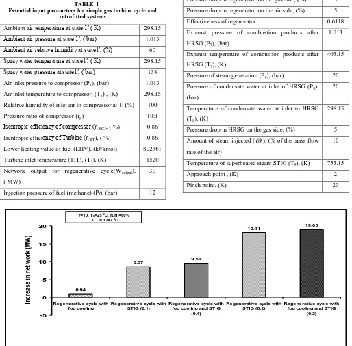
The Fig.2 represents the net increase in work output for different retrofitted cycle in comparison to regenerative cycle. The maximum value of increase in work output obtained is 19.05 for regenerative cycle combined with STIG (injection ratio 0.2) and fog cooling.
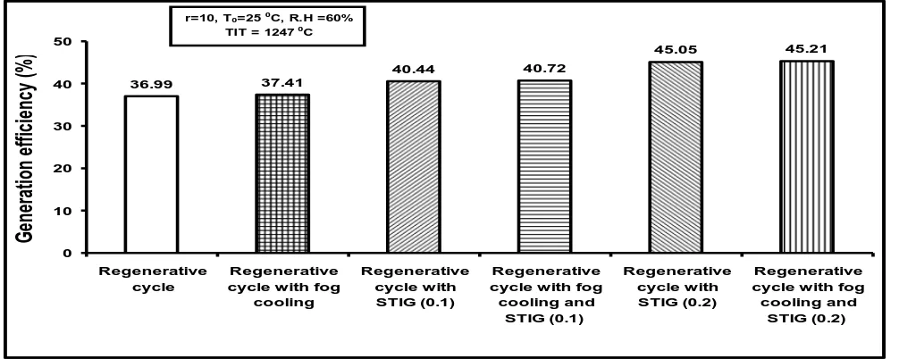
Fig.3 represents the comparison of generation efficiencies for regenerative cycle and retrofitted cycles. The maximum generation efficiency achieved is 45.21% for retrofitted combined cycle (fog cooling and STIG) with injection ratio 0.2. The trends show that the combination of fogging and STIG with simple cycle gas turbine cycle is a better approach to enhance the performance of the system on the basis of first law as well as second law.
International Journal of Emerging Technology and Advanced Engineering
Website: www.ijetae.com (ISSN 2250-2459, ISO 9001:2008 Certified Journal, Volume 2, Issue 12, December 2012)
362
The reason for decrease in first-law efficiency is that the slope of process heat is sharper than the slope of generation efficiency i.e. the reduction in process heat takes place with much faster rate. The maximum amount of injection steam is limited by the available energy recovered from the HRSG. The maximum injection ratio at 0.2 is still below the allowable injection limit (prescribed by the manufacturer) for the available industrial turbines.
The exergy destruction rate represents the wastage of available energy. Exergy destruction of all components have been calculated to enhance the overall cycle performance. Table 3 presents the exergy destruction of regenerative and retrofitted cycle components. While examine the exergy destruction for all components, the combustor has the largest exergy destruction and shows the major location of thermodynamic inefficiency because of large irreversibility arising from the combustion reaction and heat transfer. Steam injection will increase the exergy destruction due to mixing of high
temperature superheated steam (753.150C) and
compressed air (at 604.950C) into the combustor
increases the overall temperature of combustor. The exergy-losses at position 7 (see Fig.1) is considered as exergy loss through stack. Since part of exhaust heat is recovered in HRSG, the exhaust exergy out of stack can be reduced substantially after retrofitting. The exergy losses through stack will not only waste the available exergy but also dump the thermal pollution to our living environment.
Exergetic efficiency for each component can be
defined as the ratio of
E
R toE
S, whereE
S is theexergy rate supplied to the component and
E
R is theexergy rate recovered from the component. For a retrofitted cycle with fog cooling and STIG, exergetic
efficiencies of compressor, turbine, combustor,
regenerator and HRSG are respectively 93%, 94%, 71%, 84% and 79%, among which gas turbine and compressor have higher exergetic efficiency. This implies most of the exergy destruction in combustor and compressor is inevitable. It is interesting to note that the exergy destruction rate of combustor is the highest. Exergy efficiency of regenerator and HRSG is higher than that combustor. Due to maximum injection ratio limitation, there is about 5.5MW heat remain available into superheated steam. Therefore, there is a greater improvement margin exists for HRSG than for combustor.
Comparison of regenerative cycle gas turbine with and without FC (table 2) shows that exergetic efficiency gets also improve by 0.4%. However fuel-air ratio increases by 0.6%. Comparison of regenerative cycle gas turbine with and without STIG shows that exergetic efficiency gets also improved by 23.1% however fuel-air ratio increases by 17.7%.
[image:9.595.321.543.236.389.2]Exergy destruction increases in each system component except air compressor due to mixing of steam and air. Comparison of regenerative cycle gas turbine with and without FC and STIG shows that exergetic efficiency gets also improve by 23.02% however fuel-air ratio increases by 18%. The exergy destruction gets increased in each system component due to increasing mass flow rate.
Fig. 4- The effect of steam injection ratio on first-law efficiency, generation efficiency and process-heat for regenerative cycle
combined with fog cooling and STIG
However with increasing amount of STIG, exergy destruction rate of each component increases except combustion chamber and compressor.
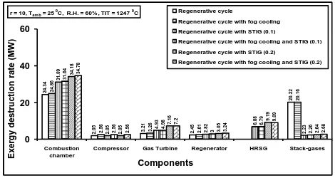
The exergy destruction rate (MW) for different system components of regenerative and retrofitted cycle has been shown in Fig. 5. The power output increases for large amount of STIG due to increasing mass flow rate of air and steam mixture. While the exergy destruction rate increases into the Combustion chamber, turbine, regenerator and HRSG. The exergy destruction in combustion chamber is highest among all the system components due to highest temperature of combustion chamber. 2 4 .3 4 2 .0 5 3 .2 1 2 .4 5 2 0 .2 2 2 4 .8 6 2 .5 6 3 .2 6 2 .6 1 2 0 .1 6 3 1 .0 9 2 .0
5 4.9
3
2
.8
2 6.8
8 2 .2 3 3 1 .6 4 2 .5
6 4.98
3 6 .7 9 2 .2 6 3 4 .1 8 2 .0 5 7 .1 6 3 .0 5 9 .1 9 2 .6 4 3 4 .7 8 2 .5
6 7.2
3 .2 4 9 .0 9 2 .6 8 0 20 40 60 Combustion chamber
Compressor Gas Turbine Regenerator HRSG Stack-gases
Components Ex e rg y d e s tr u c ti o n r a te (MW ) Regenerative cycle Regenerative cycle with fog cooling Regenerative cycle with STIG (0.1) Regenerative cycle with fog cooling and STIG (0.1) Regenerative cycle with STIG (0.2) Regenerative cycle with fog cooling and STIG (0.2) r = 10, Tam b = 25
0
C, R.H. = 60% , TIT = 1247 0
C
Fig. 5- Comparison of exergy destruction rate of system components for regenerative and retrofitted cycle (fog
[image:9.595.322.557.588.713.2]International Journal of Emerging Technology and Advanced Engineering
Website: www.ijetae.com (ISSN 2250-2459, ISO 9001:2008 Certified Journal, Volume 2, Issue 12, December 2012)
363
The results predicts that as the steam injection increases the amount of stack-losses reduces appreciably up to some extent (for STIG 0.1) and further increases slightly (for STIG 0.2). The exergy destruction in combustion chamber increases with increasing amount of STIG due increasing amount of air and steam mixture. The exergy destruction rate (MW) per MW of power output for different system components with different amount of STIG has been shown in Fig. 6.
Due to significant increase in power output the rate of exergy destruction (MW) per MW of power output reduces for combustion chamber, compressor and stack -gases while increases for gas turbine due to increasing mass flow rate (mass flow rate of air from compressor plus mass flow rate of superheated injected-steam with lower exergy).
VI. CONCLUSIONS
With the rapidly increasing demand for electricity in the developed countries like India, and the expected shortage in power supply due to delays in the major power projects, retrofitting regenerative gas-turbines with inlet air pre-cooling and STIG are attractive investment opportunity. Recovering the energy from the exhaust gas of a regenerative cycle can be used back to the system to improve the system performance. Steam injection and inlet air evaporative cooling are well-proven technology that can effectively improve power output and power generation efficiency for a regenerative cycle gas turbine. In the present work, a regenerative cycle gas turbine has been investigated. An existing regenerative cycle gas turbine was considered as the basic system and has been converted into modified retrofitted system with either the IAC or /and STIG features. The steam needed in the STIG feature is generated from the energy recovered from the system’s own exhaust gases.
Under the average local weather conditions (250C and
60% RH), the benefit of adding the STIG feature can substantially improve the power output from the 30 MW to 38.57 MW and power generation efficiency from 36.99 to 40.44%. The maximum power that can be reached by the system with both IAC and STIG features is 49.05 MW for steam injection pressure ratio at 0.2. Although the steam injection will increase the total exergy losses, the exergy loss per MW output is much smaller than that of regenerative cycle. It also reveals that the degree of energy wasting and thermal pollution can be reduced through retrofitting.
REFERENCES
[1 ] Nishida K., Takagi T., Kinoshita S. 2005. Regenerative steam-injection gas turbine systems, Applied Energy 81 (2005) 231-246; Japan.
[2 ] Hawaj O. M., Mutairi H, A. 2007. combined power cycle with absorption air cooling, Energy 32 (2007) 971-982, Kuwait. [3 ] Pelster S., Favrat D.,Von Spakovsky M. R. 2001. The thermo
economic analysis and environomic modeling and optimization of the synthesis and operation of combined cycle with advanced options, Engineering for gas turbine and power, transaction of the ASME 123 (2001) 717-26.
[4 ] Bhargava R. & Meher-Homji C. B. 2005. Parametric analysis of existing gas turbines with inlet evaporative and overspray fogging, Journal of Engineering for gas turbines and power 127 (2005) 145; Houston.
[5 ] Chaker M., Homji C. B. M., Mee I. I. I. T. 2004. Inlet fogging of gas turbine engines-part II: fog droplet sizing analysis, nozzle types, measurement and testing, Journal of engineering for gas turbines and power 126 (2004) 559, Monrovia.
[6 ] Bansode S., Sinha R., A. 2010. thermodynamic analysis for gas turbine power optimization by fog cooling system, 20th national and 9th International ISHMT-ASME heat and mass transfer conference (2010).
[7 ] Alexis G. K. 2007. Performance parameters for the design of a combined refrigeration and electrical power cogeneration system, International journal of refrigeration 30 (2007) 1097-1103, Greece. [8 ] Kumar A., Kachhwaha S. S., Mishra R. S. 2010.
Thermodynamics analysis of a regenerative gas turbine cogeneration plant, Journal of Scientific & Industrial Research, 69
(2010) 225-231; India.
[9 ] Wang F. J. & Chiou J. S. 2004. Integration of steam injection and inlet air cooling for a gas turbine generation system, Exergy conversion and Management, 45 (2004) 15-26, Taiwan; ROC. [10 ]Bilgen E, Exergetic and engineering analysis of gas turbine based
cogeneration systems, Energy 25 (2000) 1215-1229, Canada. [11 ]Ondryas I. S., Wilson D. A., Kawamoto M., Haub G. L. 1991.
Options in gas turbine power augmentation using inlet air chilling, Journal of Engineering for gas turbines and power 113 (1991) 205.
0 .8 1 0 .0 7 0 .1 1 0 .0 8 0 .6 7 0 .8 0 .0 8 0 .1 1 0 .0 8 0 .6 5 0 .8 1 0 .0
5 0.13
0
.0
7 0.18
0 .0 6 0 .8 0 .0
6 0.13
0
.0
8 0.1
7 0 .0 6 0 .7 1 0 .0
4 0.1
5
0
.0
6 0.1
9 0 .0 5 0 .7 1 0 .0
5 0.1
5
0
.0
7 0.1
9 0 .0 5 0 0.5 1 1.5 2 Combustion chamber
Compressor Gas Turbine Regenerator HRSG Stack-gases Components E xe rg y d es tr u ct io n r at e (M W )/M W o f P o w er o u tp u t
Regenerative cycle PO = 30MW
[image:10.595.48.280.245.351.2]Regenerative cycle with fog cooling PO = 30.94MW Regenerative cycle with STIG (0.1) PO = 38.57MW Regenerative cycle with fog cooling and STIG (0.1) PO = 39.51MW Regenerative cycle with STIG (0.2) PO = 48.11MW Regenerative cycle with fog cooling and STIG (0.2) PO = 49.05 r = 10, Tam b = 25 0C, R.H. = 60% , TIT = 1247 0C
Fig. 6- Comparison of Exergy destruction rate (MW) per MW of output for system components for diggernent retrofitted