Rapid Prototyping and Its Role in
Supporting Architectural Design Process
Aziz, Zeeshan and Bayar, M. Sanem
Title
Rapid Prototyping and Its Role in Supporting Architectural Design Process
Authors
Aziz, Zeeshan and Bayar, M. Sanem
Type
Article
URL
This version is available at: http://usir.salford.ac.uk/id/eprint/50159/
Published Date
USIR is a digital collection of the research output of the University of Salford. Where copyright
permits, full text material held in the repository is made freely available online and can be read,
downloaded and copied for noncommercial private study or research purposes. Please check the
manuscript for any further copyright restrictions.
For more information, including our policy and submission procedure, please
Case Study
Rapid Prototyping and Its Role in Supporting Architectural
Design Process
M. Sanem Bayar
1and Zeeshan Aziz
2Abstract:Model making is a crucial part of the design development for evaluating the form,fit, and functionality of a design before a notable investment is made. The emergence of novel technologies and their increasing uptake are helping to redefine the architecture and the archi-tects’master builder role by altering the way architects think and make things. Different methods and strategies are available to utilize for the production of artifacts that are considered not only to be new communication and representation tools but also are being utilized for testing and evaluation during design processes. Rapid-prototyping processes are forming a language for use between different phases of the design and are considered as a feedback mechanism informing each other. This article presents the experimental research products of two rapid-prototyping technologies, focusing on how each technology can effectively be used in the delivery of design intent. Prototyping machines were used in testing the accuracy of the geometry of the design, in terms of protecting the design intent within the production process of each model. To verify the results of the experiment, researchers conducted semistructured interviews with the experts in the built environ-ment, and a preliminary decision-making matrix was generated, aiming to provide guidance to the architectural designers on how to effec-tively use the current rapid-prototyping technologies within design processes.DOI:10.1061/(ASCE)AE.1943-5568.0000307.©2018 American Society of Civil Engineers.
Author keywords: Rapid prototyping; Model making; Complex surfaces.
Introduction
Architects use many forms of representation for their designs, ranging from physical to digital, two-dimensional (2D) to three-dimensional (3D), sketches to drawings, from renderings and ani-mations to movie clips. Among all these representational media, the physical model helps designers a great deal in portraying their ideas. Whether it is a student conveying a design idea across to lecturers, an architect presenting her design to a client, or an archi-tect giving building instructions to a contractor, physical represen-tation and model making are considered an integral component of the architectural design process.
For many centuries, models have been used to explain complex construction details to builders and considered to be fundamental tools of design (Gibson et al. 2002). According to Lampugnani and Millon (1994), Michelangelo, when designing the Vatican, used physical models as an intermediary to describe construction techni-ques and the form of internal spaces to both clients and stone masons. Similarly, Palladio in the sixteenth century used interme-diate models of wood as full-scale mock-ups to explain buildings to masons (Sass and Oxman 2006). The craft of architectural model making seems to have been overtaken by recent develop-ments in the area of digital renderings and virtual reality
technologies, but the importance and relevance of physical models cannot be undermined. Physical models help the designer not only in the exploration of ideas but also in communicating such ideas, as demonstrated by Michelangelo.
Prior to the advent of the digital revolution, architectural mod-els were generally made by hand by skilled craftsmen. This pro-cess was time-consuming and required highly skilled laborers. Given the manual nature of the process, physical models were not optimally used to review various design iterations. In contempo-rary computer-aided-design (CAD)-driven processes, computer modeling is used to generate various iterations of virtual models. Because of the very nature of architecture as a discipline in which the visuals are acting as part of the total sensorial experience, it is still necessary to produce physical models at the key stages of the design.
As suggested by Pham and Gault (1998), prototyping is an essential part of the product development and manufacturing pro-cess, required for assessing the form, fit, and functionality of a design prior to an investment being made. In the early stages of the design process, it is crucial for the designer to understand the choice of rapid-prototyping (RP) technology. Recent advances in RP tech-nologies allow for the development of solid physical models directly from CAD files, rapidly and precisely. Different RP proc-esses have different impacts on the product itself as a result of the varying delivery of design and communication ideas. Mellis (2011) highlights that some processes are more relevant for intricate designs and can only be produced by specific prototyping technol-ogy such as 3D printing. However, Kolarevic (2003) notes that to accelerate the design process, a faster prototyping process, such as a subtractive process [e.g., computer numerical control (CNC)] might be another choice of communication and representation. Thus, dif-ferent prototyping technologies have their own capabilities for delivery of design intent.
This article starts with an introduction of architectural model making, showing that because of technological advancements, there 1Research Assistant, School of the Built Environment, Univ. of
Salford, 4th Floor, Maxwell Building, The Crescent, Salford, Greater Manchester M5 4WT, U.K. (corresponding author). E-mail: m.s.bayar@ salford.ac.uk
2Senior Lecturer, School of the Built Environment, Univ. of Salford, 4th Floor, Maxwell Building, The Crescent, Salford, Greater Manchester M5 4WT, U.K. E-mail: [email protected]
Note. This manuscript was submitted on February 16, 2017; approved on December 8, 2017; published online on April 30, 2018. Discussion pe-riod open until September 30, 2018; separate discussions must be submit-ted for individual papers. This paper is part of the Journal of Architectural Engineering, © ASCE, ISSN 1076-0431.
is crucial demand for RP processes in the architectural design process. For architectural designers with little or no knowledge of RP technologies, a brief explanation is given. This is fol-lowed by the presentation of a research experiment that ana-lyzed the practical use of RP technologies currently used in the architectural design process. This experiment explored how RP could allow architects to alter the way they think during the design process as a result of tremendous technology improve-ments that allow designers to test and manipulate designs before they are actually manufactured. Next, the results of semistruc-tured interviews undertaken to formulate a guidance decision matrix for architectural designers are presented. This is followed by a discussion on the benefits of RP technologies in relation to architectural modeling in academia and practice during the design process. Finally, a conclusion is presented that addresses the potential of actively using RP technologies during the design process.
Literature Review
Rapid prototyping is defined as“the ability to generate models directly from computer-aided design data in a very short time” (Tut et al. 2010). These technologies are based on a group of techniques to quickly generate a scale model or assembly parts using 3D input data (Van der Zee et al. 2014). The use of RP tech-nologies provides an inexpensive, efficient, and rapid method for designers to test and validate the product from the early design stage up until the finishing stage (Sanchez et al. 2005). As a result, novel prototyping technologies (RP) have made it possible to rapidly generate physical models and form a feedback mecha-nism for new design alternatives and iterations to explore (Tomohiro et al. 2016).
Design is a process with different development stages to test and evaluate the design. Each design stage requires various scale mod-els to evaluate the design product. Ryder et al. (2002) categorized three types of models according to the stage of the design project: (1) feasibility model, (2) planning model, and (3) final project model. Ryder et al. (2002) further explained that the feasibility model is created to convey the concept of the design; not much detail is added, and sizes are usually small, but the general form of the design is conveyed. Theplanning modelis created when more details need to be conveyed and at a higher quality than in the feasi-bility model. Therefore, the designer can portray a clearer under-standing of the design and its relationship to its context. Thefinal project modelshows the actual design once it is completed. In prac-tice, this is the type of model that is shown to the clients and public. In a school setting, this could be the model for the final design intent. Furthermore, Kolarevic (2003) highlighted that introduction of digital prototyping enables architectural designers to produce scale models of their designs according to the level of detail they need to evaluate or communicate. This will be further explained in the section on design experiments.
RP technologies can be categorized into two broad categories: additive and subtractive processes. This classification is based primarily on the process of manipulation of material. The addi-tive processes(e.g., 3D printing) produce the prototype through layer-by-layer addition of material until the model is complete (Mellis 2011). This process starts with nothing and then builds up the model to completion, just like the normal construction technique. Thesubtractive processes(e.g., CNC milling), how-ever, are those in which the material is produced by the gradual, bit-by-bit removal of material from an existing block of material (Kolarevic 2003). This is the direct opposite of the additive
process because it starts with a large amount of material that is formed into the desired product through an intricate process of subtraction.
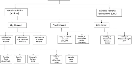
In recent literature, RP technologies have also been broadly classified based on the initial form of the material used by machines in the production of prototypes. Based on material form, RP systems can be categorized as (1) liquid based, (2) solid based, and (3) powder based. A comparison of RP technologies is presented in Fig.1, based on Kruth’s (1991) work as cited in Pham and Gault (1998). Fig.1has been adapted to show the vari-ous different RP technologies. Among the varivari-ous technologies presented in Fig.1, this article reviews two of the most com-monly used technologies: 3D printing (additive) and CNC mill-ing machine (subtractive). The selection was made because of their greater ability to fabricate complex surfaces compared with the other technologies and because they are desktop-size devices (nonindustrial machines) to fit in office or school settings. The machines are simple enough to be operated by students or archi-tectural designers with no serious technical skills with some prior training (De Bruijn 2010).
Research Experiment
This section presents the findings of a research experiment carried out to establish the effects of the use of RP technologies on the ar-chitectural design process. The experiment shows how the use of these technologies could impact or aid the overall design outcome. For the experiment, a Roland (Irvine, California) Modela Pro II MDX-540 CNC milling machine [Fig.2(a)] was used, alongside a ZPrinter 450 [3D Systems (formerly, ZCorporation) Rock Hill, South Carolina] 3D printer [Fig.2(b)]. Each RP machine uses different working principles and software for operation. These machines were used in testing the accuracy of the design geome-try in terms of protecting the design intent within the production process of each model.
This research compared RP techniques with traditional physical modeling techniques, and the research experiment highlights the potential of RP by using it in the development of a design. The research highlights the benefits of the integration of RP into the dig-ital architectural design process.
The design used in the experiment involved researchers’ small-scale pod design (geodesic dome geometry) that was cre-ated using Rhino 3D software (Fig. 3). The small-scale pod design was selected for the experiment to limit the scope of the work. The design was considered suitable for the experiment because of its geometry, which consisted of triangulation of fac-ets on its dome and an opening in the front. The design experi-ment was carried out to test the constructability of the pod and its geometric features using two RP technologies and, as such, to es-tablish the link between the use of these technologies and the design process.
Two prototypes were produced with the aid of two different RP machines, a CNC milling machine and a 3D printer. The following sections present the process of making the two prototypes. The modes of operation and requirements of these machines are dis-cussed in detail.
Prototype 1 Using CNC Milling
The first prototype was made using a CNC milling machine. A Roland Modela Pro II MDX-540 milling machine was used in producing this particular model. The only two requirements for the production of this prototype were a 3D model in .stl file
format and material for milling. To initiate the milling process, the origin of the material should be set, and the milling tools should be replaced [Figs.4(a–c)and5(a–c)].
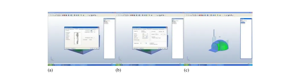
The machine uses software calledMayKa Expert 7.0. The first step was to import the .stl-format 3D model into the operating soft-ware. The scale of the model can either be predetermined or chosen based on the size of the material to be used in milling. If the object to be cut is more detailed, various types of cutting phases can be applied, such as rough cutting and finishing together, with their par-ent milling tools. The finishing process depends on the complexity of the geometry and surfaces. Once the settings were selected through the computer software, the actual fabrication began when the machine started its rough-cutting process (Figs.6and7).
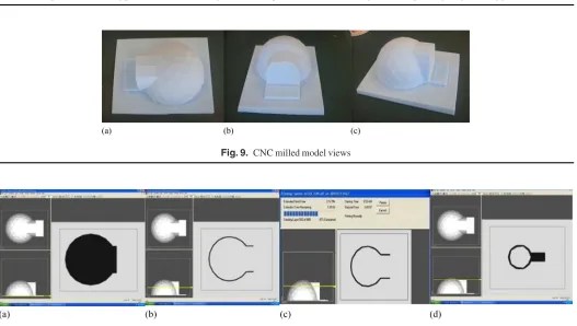
The software simulates the pattern for milling, which is sent to the machine in the same way printing jobs are sent to printers [Figs. 6(c–d)].
[image:4.612.46.569.52.307.2]Fig. 1. Classification of rapid prototyping based on the initial form of the material (Note: SGC = solid ground curing; FDM = fused deposition model-ing; SLS = selective laser sintermodel-ing; 3DP = three-dimensional printmodel-ing; LOM = laminated object manufacturmodel-ing; ES = electrosettmodel-ing; BPM = ballistic particle manufacture; 3DW = three-dimensional welding; GDP = gas-phase deposition; SF = spatial forming; SLA = stereolithography apparatus; LTP = liquid thermal polymerization; BIS = beam interference solidification; TSF = topographic shape formation; SFP = solid foil polymerization; SDM = shape deposition manufacturing) (Reprinted fromInternational Journal of Machine Tools and Manufacture, Vol. 38, D. T. Pham and R. S. Gault,“A comparison of rapid prototyping technologies,”pp. 1257–1287, © 1998, with permission from Elsevier)
Fig. 2. (a) CNC milling machine; (b) 3D printer
Fig. 3. Virtual views of the pod design
[image:4.612.97.573.388.554.2]In addition, it is possible to control the motion, feed rate, operation of the spindle drive tool changes, and other operational parameters with the help of the handy panel to accelerate the milling process. The major aim of the utilization of the CNC
[image:5.612.46.568.35.170.2]milling machine was to observe the design intent, in terms of the representation, accuracy, and effectiveness of the total geometry and its surfaces. Figs.8(a and b)show the 3D milling process in action.
[image:5.612.93.501.213.315.2]Fig. 4. (a) Handy panel showing coordinates; (b) setting the origin on the working piece with handy panel; (c) CNC milling machine before milling operation
Fig. 5. (a) CNC milling machine tool installation door; (b) tool installation per its diameter; (c)final clinching diameter tool with screwing tool
Fig. 6. (a) Importing the .stl 3D model intoMayKa; (b) defining material block size within software environment; (c and d) simulation of the milling method (rough cutting andfinishing)
Fig. 7. Software showing parameters of sweeping: (a) tool depth; (b) milling tool information; (c) sweeping simulation
[image:5.612.47.569.345.485.2] [image:5.612.42.566.519.652.2]Product 1
The model was produced at a scale of 1/100 because of the plate size and tool length of the machine used, which was suitable to eval-uate the facets and the other sections of the geometry. The final product was a closed-geometry model, although the original file sent to the machine was open (Figs.3and9). In addition, on the base point of the final product, some tiny protrusions were visible [Figs.9(c)], which can be inferred as being a result of the constraint of the milling tool length used for this implementation. The milling tool could not reach the 1–2 mm at the bottom of the model. The fabrication process of the total model took approximately 1 to 2 h, including the cleaning process.
Prototype 2 Using 3D Printing
The second prototype was built using a ZPrinter 450 3D printer. To print a 3D model, a few factors had to be considered, such as the thickness of the model to be printed (because a thin model would
directly mean a fragile model) and the required scale (considering the maximum printable size of 203254203 mm). Also, the 3D printer required a completely closed and composite model. This is because it prints the objects in layers, and spaces would result in a fragile and broken model. The software for the printing process was developed by ZCorporation (now 3D Systems) (Fig.10) and allows the user to view each layer of the printing to be done, hence provid-ing an opportunity to evaluate any problem areas. The thin horizon-tal line in Fig.10shows the produced mass in section view, and the plan view of the printed parts was also shown by the operating software.
[image:6.612.136.471.39.181.2]After the allotted time for the 3D printing, the model was col-lected from the machine’s envelope, which was full of unused powder (Fig.11). The 3D printer fabricates layer by layer accord-ing to its workaccord-ing fashion. The powder that was not used was visi-ble over the created model, which was cleaned with the machine’s vacuum and then a soft brush. Because of the model’s fragile walls, it was very carefully carried out of the envelope;
Fig. 8. CNC milling process: (a) CNC milling machine in operation; (b) CNC milling machine operating rough milling process
Fig. 9. CNC milled model views
Fig. 10. (a–c) Additive fabrication process, layer-by-layer fashion; (d) elapsed time of the 3D printing process
[image:6.612.45.572.199.497.2]after that, it had to be glued to strengthen the final 3D printed model. The leftover powder, which is high in cost, can be reused after collection with the vacuum tool, which deposits it back into the machine’s container.
Product 2
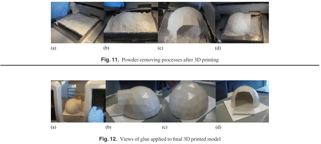
The final product was at a scale of 1/50 of the design geometry and was very fragile because of its thin walls (Fig.12). However, an exact replica of the design intent was produced. The 3D printed model was fabricated in approximately 6 h; after fabrica-tion, the model required 45 minutes for drying. After drying was complete, the powder around the artifact was vacuumed, and glue was applied to the surface. In total, the prototyping process took 6–8 h.
Comparative Analysis and Results
The analysis of the findings of the experimentation on each prod-uct centered on their accuracy in delivering the design intent/ representation.
CNC Milled Model
The experiment carried out on the CNC cut model showed that there were some limitations in the representation of the design. Some details were lost because of the length of the milling tool and the axis constraints. The opening at the front the pod and the dome’s inner space were lost. Although the .stl-format model that was sent to the computer software was accurate in showing the open space, the machine recognized the design as one solid mass. Another con-straint detected was the scale because of the size of the plate. The scale of the product could not exceed the plate size. The tool length was not enough to reach the very bottom of the geometry; therefore, in the final product, there were some visible tiny protrusions around the total mass. The facets on the dome were visible enough to com-municate the design intent.
3D Printed Model
The 3D printed product was an exact replica of the actual 3D pod design produced by the design software (Figs.3and12). The final product was very realistic and accurate as per idea delivery, and the
design intent was protected. The representation was realistic and relevant. The 3D printed design outcome proved that design intent was maintained. However, the product itself was very delicate to carry.
The results of the experiment show that 3D printing was able to accurately represent complex geometries and surfaces in terms of its delivery of design intent. It was able to fabricate an exact replication of the 3D design that was created by the software. Conversely, the results of the CNC milling experiment show that although the representation was accurate for the surfaces of the geometry, it was inaccurate for the representations of empty space.
[image:7.612.42.572.33.271.2]The experimentation results were evaluated by five semi-structured interviews conducted with architectural practitioners and design academics in the field of architecture. The final prod-ucts were shown to the experts for comparison (Fig.13). The interview results suggested that the accuracy level of the 3D printing machine was very highly dependent on the material types that additive technology uses. Because of the 3D printer’s powder material, the product can be very fragile and could be very difficult to construct based on the layer-by-layer principle. Other points noted for 3D printing include the slow processing time resulting from its layer-by-layer fashion and the high cost of materials. In this case, the quick model generation by the CNC milling machine made it more preferable for use compared with the 3D printer. However, the 3D printer was very user-friendly compared with the CNC milling machine. Therefore, CNC tech-nologies could be an option to deliver ideas quickly in different stages of the design because of their low cost and speed. The CNC milling machine was very accurate for surfaces and could rapidly produce mass models at an optimum level. However, pre-cise models with more accurate surfaces can be fabricated with the 3D printer. Typically, models created with 3D printers are brittle but can be strengthened with different powders and adhe-sives. The biggest disadvantage of the 3D printer is the postpro-cessing step, which can be messy and tedious because of the powder that remains after the 3D printing, which needs to be cleaned and vacuumed from the fabricated model. Both machines require no monitoring during the process once they are set for the fabrication. In conclusion, although the RP
[image:7.612.124.493.37.117.2]Fig. 11. Powder-removing processes after 3D printing
Fig. 12. Views of glue applied tofinal 3D printed model
technologies are very convenient for producing various models in different design phases, the machines require some level of training for operation.
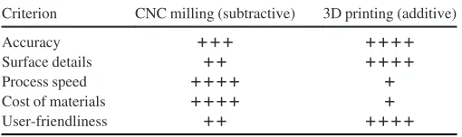
According to the evaluation of the experiment, to provide guidance to architectural designers, the researchers generated a preliminary decision-making tool (Table 1) and verified the results with the experts during the interviews undertaken. Table1 shows an evaluated matrix for designers to consider prior to using the RP technologies, noting the accuracy, delivery of design ge-ometry, process speed, cost of material, and user-friendliness for each RP technology.
The outcome of the design experiments can be supported by Seely’s (2004) extensive research on RP technologies. Although the modes of operations and functions differ to a large extent, some general factors can be compared, such as user-friendliness, size, materials, interaction, speed, and price.
Discussion
This study reviewed the benefits and demerits of two RP technolo-gies carried out through the application of two experiments. Moreover, the benefits and supportive role of these technologies in the architectural design process were analyzed, and practical results were given by forming a decision-making matrix.
The practice and educational requirements for the RP technol-ogies are different. For students, the aim is to learn; therefore, they have the freedom of testing various prototyping processes in different design stages. Conversely, for architectural designers in practice, the aim is to quickly and accurately deliver the design ideas to clients. The new generation of architectural practitioners is partially aware of the RP technologies. However, many of them are not aware of the benefits of current digital prototyping technologies; few firms are using these technologies in various design stages. The RP technologies should be utilized in the ar-chitectural field to maximize design performance during design stages. In conclusion, the advantages of the RP technologies should be introduced both to academia and to the field of archi-tecture and construction as an essential integrated part of the design process.
Conclusion
Technologically driven change has always been a catalyst for new ideas in architecture, and today, digital technology is a key agent for innovation in design and construction (Klinger 2001). Timely assessment of design concepts has given the possibility of generation and elaboration of new ideas. A digitally proto-typed model is something greater than an image on a computer screen; it gives the possibility of testing the accuracy of the digi-tally driven designs. RP offers architectural designers the ability to think of ways to translate computed designs into a tangible medium, allowing a variety of constructible designs rather than abstract objects. With the help of RP, acceleration of the process can be achieved. The data are protected during the stages of the design pro-cess, which has been a challenge for many years in design practice. Rapid prototyping of a model means that more designs can be con-sidered and tested in a shorter period of time. Potential manufac-turing problems that are caused by a part of the design can be iden-tified before full fabrication begins. Not only does the design process move quicker, but the quality of the design is likely to improve as well.
References
De Bruijn, E. (2010).“On the viability of open source development model for the design of physical objects.”hhttp://thesis.erikdebruijn.nl/master
/MScThesis-ErikDeBruijn-2010.pdfi.
Gibson, I., Kvan, T., and Ming, L. W. (2002).“Rapid prototyping for archi-tectural models.”Rapid Prototyping J., 8(2), 91–95.
Klinger, K. R. (2001).“Making digital architecture: Historical, formal and structural implications of computer-controlled fabrication and expres-sive form.”Proc., Education in Computer Aided Architectural Design in Europe (eCAADe) Conference 2001: Architectural Information Management. Helsinki Univ. of Technology, Helsinki.
Kolarevic, B. (2003).Architecture in the digital age: Design and manufac-turing, Taylor&Francis, Abingdon, U.K.
Lampugnani, V., and Millon, H. (1994).The Renaissance. Rizzoli, New York.
MayKa Expert 7.0[Computer software]. PicaSoft, Vierzon, France. Mellis, D. A. (2011).“Case studies in the digital fabrication of open source
consumer electronic products.”M.S. thesis, Massachusetts Institute of Technology, Cambridge, MA.
Pham, D. T., and Gault, R. S. (1998).“A comparison of rapid proto-typing technologies.” Int. J. Mach. Tools & Manuf., 38(10–11),
1257–1287.
Rhino 3D[Computer software]. Robert McNeel&Associates, Seattle. Ryder, G., Ion, B., Green, G., Harrison, D., and Wood, B. M. (2002).
“Rapid design and manufacture tools in architecture.”Autom. Constr.,
11(3), 279–290.
Sanchez, J., Gonzalez, J., and Oyarbide, A. (2005).“Using rapid prototyp-ing for free-form shapes in architectural scale models.” Proc., Int. Association for Shell and Spatial Structures, International Assoication for Shell and Spatial Structures, Madrid, Spain.
[image:8.612.129.488.37.126.2]Sass, L., and Oxman, R. (2006).“Materializing design: The implications of rapid prototyping in digital design.”Des. Stud., 27(3), 325–355.
Fig. 13. Views of design products used during semistructured interviews: (a) additive process; (b and d) subtractive processes; (c) additive process
Table 1.Decision-Making Matrix for Rapid Prototyping
Criterion CNC milling (subtractive) 3D printing (additive)
Accuracy 111 1111
Surface details 11 1111
Process speed 1111 1
Cost of materials 1111 1
User-friendliness 11 1111
Note:þþþþ= adequacy;þ= inadequacy.
[image:8.612.42.297.177.253.2]Seely, J. C. K. (2004).“Digital fabrication in the architectural design process.” M.S. thesis, Massachusetts Institute of Technology, Cambridge, MA.
Tomohiro, F., Tokuhara, T., and Yabuki, N. (2016).“A dynamic physical model based on a 3D digital model for architectural rapid prototyping.” Autom. Constr., 72(1), 9–17.
Tut, V., Tulcan, A., Cosma, C., and Serban, I. (2010).“Application of CAD/CAM/FEA, reverse engineering and rapid prototyping in manu-facturing industry.”Int. J. Mech., 4(4), 79–86.
Van der Zee, A., de Vries, B., and Salet, T. A. M. (2014).“From rapid proto-typing to automated manufacturing.” Proc., 32nd eCAADe Conf., Northumbria Univ., Newcastle upon Tyne, U.K., 445–461.