Building assessment during disaster
response and recovery
PeñaMora, F, Aziz, ZUH, Chen, A, Plans, A and Foltz, S
http://dx.doi.org/10.1680/udap.2008.161.4.183
Title
Building assessment during disaster response and recovery
Authors
PeñaMora, F, Aziz, ZUH, Chen, A, Plans, A and Foltz, S
Type
Article
URL
This version is available at: http://usir.salford.ac.uk/23102/
Published Date
2008
USIR is a digital collection of the research output of the University of Salford. Where copyright
permits, full text material held in the repository is made freely available online and can be read,
downloaded and copied for noncommercial private study or research purposes. Please check the
manuscript for any further copyright restrictions.
Proceedings of the Institution of Civil Engineers
Urban Design and Planning 161
December 2008 Issue DP4 Pages 183–195
doi: 10.1680/udap.2008.161.4.183
Paper 800032
Received 30/05/2008 Accepted 08/09/2008
Keywords: buildings, structures & design/disaster engineering/ information technology
Building assessment during disaster response and recovery
F. Peña-Mora
MS,PhD, Z. Aziz
MS,
PhD, A. Y. Chen
MS, A. Plans
MSand S. Foltz
MSDuring disaster response and recovery operations, civil engineers can be assigned a multitude of tasks including triage of building search priorities, identifi ca-tion and evaluaca-tion of structural hazards, as well as the development of appropriate structural hazard mitigation techniques and monitoring of hazards, while coordinating and reporting this information to the incident command centre (ICC). This paper reviews the role of civil
engineers in disaster response with a focus on existing building assessment and marking systems and highlights various limitations of existing approaches. A mobile information technology (IT)-based collaborative framework is discussed to facilitate a coordinated disaster response and recovery operation. It enables engineers to assess building damage better and to make this information available to personnel more quickly and easily within the disaster area and thereby improve disaster response. The deployed architecture is com-posed of various components including radio frequency identifi cation (RFID)-based structural assessment, a fi eld engineer’s mobility and information support platform and geographic information systems (GIS)-based resource optimisation. Deployed infrastructure enables the on-site and on-demand information provisioning, data processing and computational support required by engineers in the aftermath of a disaster.
1. INTRODUCTION
Modern cities are complex and rely on inter-dependent systems including a mix of utilities, transportation and telecommunica-tion infrastructure, commercial and residential building; this makes them extremely vulnerable. The critical role played by civil engineers to promote urban resilience has long been recognised.1–3 Technically sound and timely decisions by
engineers may mean the difference between life and death in a disaster response operation.4 A signifi cant role for civil
engineers to promote urban resilience through application of engineering expertise including structural, construction, geotechnical, environmental, hydraulic and transportation knowledge has previously been emphasised.3 Table 1
summarises key facets of the role of civil engineers during disaster response operations to attain high levels of disaster resilience.
A well-planned, prompt and accurate building damage assessment and reporting procedure is vital to ensure effective
disaster response and recovery and in restoring/improving pre-disaster built environment conditions. The structure triage, assessment and marking system is designed to help identify, select and prioritise building(s) with the highest probability of success with respect to fi nding and rescuing live victims.5 The
system assists engineers in evaluating several buildings to determine which structures will receive operational priority. The priority is based on a score, which is infl uenced by the building’s occupancy, collapse mechanism, time to get to victims, prior intelligence, resources available and structural condition. Buildings with higher scores receive attention fi rst, to improve the search and rescue performance.6
The current research paper presents the work done related to the building assessment component of the ‘collaboration for preparedness, response and recovery’ (CP2R) project,7 which
has focused on improving the collaboration among the key actors that should be involved in preparedness against disaster (i.e. beforehand), response and recovery to disaster (i.e. afterwards) in reacting to extreme events (XEs) involving critical physical infrastructure. The rest of the paper is organised as follows. Section 2 reviews most commonly used post-disaster building assessment marking systems used in the USA, whereas section 3 discusses the state of the art in building assessment procedures and new technologies used to support it. Section 4 analyses limitations of existing post-disaster building assessment approaches. Section 5 discusses a mobile informa-tion technology (IT) system architecture and implementainforma-tion to address various limitations. Field trials undertaken to validate the system are discussed in Section 6 and conclusions are drawn about the possible future impact of this work in Section 7.
2. REVIEW OF POST-DISASTER BUILDING ASSESSMENT AND MARKING SYSTEMS
A key objective of post-disaster building assessment and marking systems (BAMS) is to communicate buildings’ stability and suitability information to all concerned personnel involved in disaster response and recovery for performing rescue, recovery or crime investigation activities inside the building. BAMS ensure that rescue teams are aware of hazardous areas in damaged buildings. Thus, it is important that information related to building identifi cation, conditions, hazards and victim status be marked in a standardised fashion. In an urban environment building marks also serve as a communication channel between engineers, fi re-fi ghters (local and regional level) and task forces (federal level) and often help to keep
Feniosky Peña-Mora
Professor of Construction Management and Information Technology, University of Illinois at Urbana-Champaign, Illinois, US
Zeeshan Aziz
Research Associate, University of Illinois at Urbana-Champaign, Illinois, US
Albert Chen
PhD Student, Civil and Environmental Engineering Department, University of Illinois, Illinois, US
Albert Plans
PhD Student, School of Industrial Engineering, University of Politècnica de Catalunya, Barcelona, Spain Stuart Foltz
.
track of their location. Different BAMS are often deployed in disaster response operations and are often used to pursue different goals. They have been used in almost all major disasters in the US in recent years. The most commonly used BAMS are discussed below.
2.1. National urban search and rescue response system
The US Federal Emergency Management Agency (Fema) (US&R) response system6 is the national standard system for
identify-ing, evaluating and marking buildings. It was established to ensure differentiation of structures within a geographic area and to communicate the structural condition and status of US&R operations within a structure. The marking is divided into four categories for identifi cation, structure/hazards evaluation, victim location and search assessment marking.6
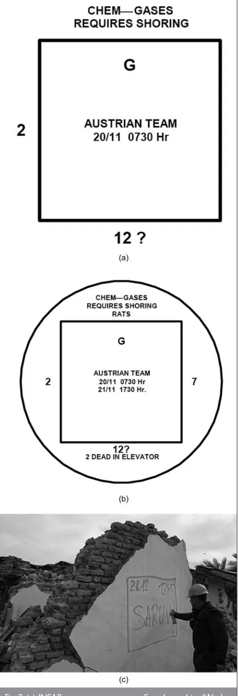
Building marks are made on structures with international orange paint, and placed on the building surface or a nearby
Engineering activities Planning activities
• Identify structural hazards that threaten the safety of rescue personnel and propose safest routes to reach survivors
• Design structural hazard mitigation measures, including shoring and bracing for unstable structures
• Identify alternatives for mitigation of structural hazards to minimise risks to rescue personnel
• Monitor structural stability under changing conditions • Identify dangers posed by loose debris and recommend
priority of removal
• Provide orientation and marking within a structure • Assist with safe placement and operation of heavy
equipment
• Triage collapse area for search operations
• Assessment of structures adjacent to immediate disaster area
• Identify likely void locations to assist locating victims
• Initialise structure triage and assessment
• Coordination and exchange of all other pertinent information such as
°
structure assessments°
mitigation plans, logs and priorities°
monitoring plans and logs°
prioritise, coordinate and provide design support for hazard mitigation [image:3.595.49.535.63.265.2]• Help manage and coordinate the work of contractors
Table 1. Role of civil engineers in disaster response
fl at surface (Fig. 1). This specifi c colour is actually assigned to US&R building marks because of its clear visibility, showing key assessment information to all the personnel involved in operations.
2.2. International search and rescue response system
The international search and rescue response system (INSAR)9
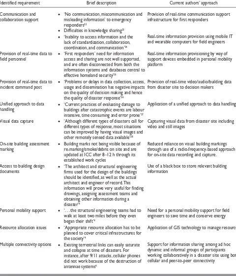
was created to assist international search and rescue (SAR) teams. It includes a complete framework to develop the SAR activities, including a building marking system to assess buildings in a disaster event, which seeks to standardise the way to post the information to ensure uniformity and clarity. Information is posted with fl uorescent colour (Fig. 2) to identify and mark structures permanently. The INSAR system is divided into various categories including assigned areas or work site, structure assessment, general hazards marking, facility/vehicle markings, potential void identifi cation, team/functional markings, symbols and signalling.
[image:3.595.40.542.584.769.2]2.3. Applied Technology Council12
The Applied Technology Council (ATC) has developed different manuals detailing procedures for post-disaster building assessment. Their use is recommended for the following disaster types: earthquakes, windstorms, hurricanes, snow storms, fi res, fl oods, tsunamis, blasts, crashes and terrorist incidents.2 ATC
has various fi eld manuals which give advice on evaluating structural, geotechnical and non-structural risks, and on estimating the impact to safety of different types of building damage. The focus of the manuals is on buildings, and not on other engineering facilities such as bridges or pipelines. Unlike US&R and INSAR, the marking system is for recovery, not rescue. The ATC-20 procedures gained a great acceptance owing to their deployment after the 9/11 attacks, and now they have become a de facto standard for rapid structures inspection of buildings and other structures in the US.2 ATC procedure
defi nes three levels of evaluation, namely, rapid, detailed and engineering evaluation developed for different personnel (Fig. 3).
To specify clearly the extent of a building damage, the ATC procedures include a standard method to identify buildings through three levels of colour-coded placards. Table 2 highlights the main characteristics for each class.
To facilitate the collection and management of data, ATC and Buidfolio Incorporated developed the ATC-20i14 personal digital
assistant (PDA) application. This enables engineers to document inspection results using electronic input screens that duplicate the ATC-20 rapid and detailed evaluation forms and to upload the data by way of wireless technology, or the internet, to a server where the data can be reviewed, summarised and managed by the user and by building departments.
3. APPLICATION OF TECHNOLOGIES TO FACILITATE BUILDING ASSESSMENT
In recent years various research groups and commercial organisations have focused on application of emerging technologies to facilitate building assessment. Various approaches of macro-level building damage assessment using satellite imagery and remote sensing are also proposed.15,16
Sextos et al.17 presented a computer-aided strategy for the rapid
visual inspection of buildings and prioritisation of strengthen-ing and remedial actions usstrengthen-ing computer-aided pre/
post-earthquake buildings assessment involving database compilation, geographic information system (GIS) visualisation and mobile data transmission. Earthdata International18 has
used mapping techniques (based on sensorial gathering of data) in buildings for several purposes. As part of air-borne rapid imaging for emergency support (aries) project, Earthdata18 is
focusing on gathering and processing multi-sensor geospatial information, integrating existing tabular data and producing high-quality information in a minimum of time between data collection and delivery of products to fi rst responders. Researchers have also highlighted the importance of three-dimensional laser scanning tools to assess building damage in the response phase of an extreme event.19 Behzadan et al.20
discussed application of ubiquitous hybrid location tracking technology that could automatically provide engineers and fi rst responders with accurate, prioritised contextual informa-tion by retrieving previously stored building informainforma-tion and superimposing that information on a real building using augmented reality to evaluate building damage,
[image:4.595.58.300.42.748.2].
structural integrity and safety. Digital measurements are also used to complement on-site building observation. For instance, the Exponent wireless building monitoring system21 allows,
through its sensors, a real-time monitoring of the building’s tilt angle. The sensors are attached to columns and/or beams, and once they are initialised to the benchmark position, every 5 s an updated position is broadcast to the receivers. Receivers send data gathered to the PDA or laptop by way of a Bluetooth component. In the case where the original conditions change (e.g. slight movement in buildings), the system automatically launches an alarm state.
While the aforementioned initiatives have concentrated on using individual technology components to support building assessment during disaster response, there is a need for an integrated framework and a holistic approach to support building assessment operations as part of disaster response.
4. LIMITATIONS OF EXISTING POST-DISASTER BUILDING ASSESSMENT APPROACHES
[image:5.595.46.540.43.346.2]The various BAMS discussed in section 2 differ in terms of their scope and focus, and very often different marking systems are used within the same disaster zone at the same time by different agencies involved in disaster response and recovery efforts. Frequently, different BAMS are used at local, regional and national levels. The presence of different building marking systems introduces complexity in their understanding. Rescue– recovery teams have to deal with a large number of symbols. Different organisations, with different marking systems, means duplication of work. Literature review and detailed interviews with experienced personnel from the Illinois Fire Service Institute (IFSI) and the US Army Corps of Engineers, who have been involved in disaster response for the 9/11 terrorist attacks, Hurricane Katrina and numerous other disasters, have provided some insight into various obstacles to effective disaster
Fig. 3. Flowchart illustrating (a) building safety evaluation process and (b) building evaluation techniques12
Colour Posting classifi cation Description
Green Inspected No apparent hazard found, although repairs may be required. Original lateral load capacity not signifi cantly decreased. No restriction on use or occupancy
Yellow Limited entry/ restricted use
Dangerous condition believed to exist. Entry by owner permitted only for emergency purposes and only at own risk. No usage on a continuous basis. Entry by public not permitted. Possible major aftershock hazard
Red Unsafe Extreme hazard, may collapse. Imminent danger of collapse from an aftershock. Unsafe for occupancy or entry, except by authorities (entry controlled by jurisdiction)
response (Table 3). The approach taken to address these obstacles is also briefl y discussed and further explained in section 4. Table 4 maps identifi ed user requirements with CP2R component technologies.
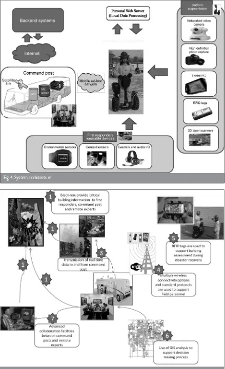
5. SYSTEM ARCHITECTURE AND IMPLEMENTATION
Figure 4 describes the system architecture, which is composed of various components including radio frequency identifi cation (RFID)-based structural assessment, a fi eld engineer’s mobility and information support platform and a GIS-based resource
optimisation component. The system provides the required computing infrastructure such as onboard processing, database accessibility and storage, software access and immediate communication tools to overcome past limitations. Implemen-tation of the system components is discussed in the following subsections.
5.1. RFID-based building assessment
Radio frequency identifi cation technology is used as the basis of a structural assessment system (Fig. 5). Supported by
Identifi ed requirement Brief description Current authors’ approach
Communication and collaboration support
• ‘No communication, miscommunication and misleading information’ to emergency responders22
• Diffi culties in knowledge sharing23
Provision of real-time communication support infrastructure for fi rst responders
• ‘Inability to access information and the lack of standardization, collaboration, coordination, and communication’24
Real-time information provision using mobile IT and wearable computers for fi eld engineers
Provision of real-time data to fi eld personnel
• ‘First responders’ need for information access and sharing are not well supported, and are often disconnected from both the information systems and databases central to effective homeland security’25
Real-time information provisioning by way of support devices embedded in personal mobility platform
Provision of real-time data to incident command post
• ‘Problems or delays in data collection, access, usage and dissemination has negative impacts on the quality of decision making and hence the quality of disaster response’26
Provision of real-time video/audio/building data from disaster site to decision makers
Unifi ed approach to data handling
• ‘Current practices of evaluating damage to buildings after catastrophic events are labour intensive, time consuming and error prone’27
Application of a unifi ed approach to data handling
Visual data capture • ‘Although different types of disasters call for different types of response, most situations can be improved by having visual images and other remotely sensed data available’28
Capturing visual data from disaster site including video and still images
On-site building assessment marking
• Building marks not being visible because of re-marking/smoke/debris on site and are updated at ICC after 8–12 h through its established work cycles
Reduced reliance on visual building markings through use of a radio-frequency-based approach for on-site data recording and capture.
Access to building design documents
• ‘The architect and structural engineering fi rms used for the design of the buildings should be identifi ed, as well as the actual architect and engineer of record. This information will prove very useful for fi nding drawings, assigning assessment teams and obtaining other information during a disaster’4
Use of a black box to store relevant building information
Personal mobility support • ‘. . . the structural engineering teams had to walk at least two miles before they even began their shift’4
Need for a personal mobility support for fi eld engineers to save time and conserve energy
Resource allocation issues • ‘Appropriate resource allocation has to be planned to cover critical infrastructures for the society’4
Application of GIS technology to manage resources
Multiple connectivity options • Existing terrestrial links can easily saturate and collapse at time of disasters. For instance, after 9/11 attacks, cellular phones did not work because of the destruction of antennae systems4
[image:6.595.63.543.203.763.2]Support for information sharing among ad hoc dynamic and informal groups of participants working collaboratively in a disaster site using both cellular and peer-to-peer connectivity
.
wireless client-to-server and peer-to-peer applications, RFID-enabled mobile devices and tags represent a method for posting, gathering, storing and sharing information related to building assessment in a timely manner, leading to an im-proved effi ciency and effectiveness of the emergency response.7
Client application was developed on a pocket-PC platform, while the building assessment module was developed in C# using Microsoft.NET framework 2.0 and Compact framework 2.0. extensible mark-up language was used for data exchange. On-site building assessment information is stored on RFID tags attached to buildings. Building assessment information is also stored in the virtual domain using a PDA-based electronic map. Information about all the assessed building within the range of a particular ad hoc network will be displayed on the electronic map. The global positioning system (GPS) extension of the software enables automatic updating and visualisation of the fi eld engineer’s location as they comb the disaster site to make assessments of the existing disaster situation. Along with the RFID approach, building information hubs (the building equivalent of the ‘black box’) were developed.29 These
intelligent units provide dynamic building information through sensors such as temperature, humidity, personnel location and stresses in structural elements. Additionally, the units contain details of building drawings and historical records that can also support the engineering assessments. Special effort is directed towards disaster survivability, communications and redundancy requirements to provide real-time sensed information to remote teams and to integrate these data in structural models for accurate analysis during and after disasters.
5.2. Personal mobility and information provisioning platform
During disaster response and recovery operations time is of the essence. ‘The elapsed time directly translates into signifi cant economic losses and to circumstances in which humans are exposed to precarious working and living conditions.’27 Thus,
there is a need to employ innovative solutions to increase access of critical responders to chaotic, hazardous and hostile environments. A mobility platform is used to enable engineers to undertake initial damage reconnaissance and building
Identifi ed user requirements
CP2R component technologies
RFID GIS Building black box Mobility platform Photo capture Video capture GPS Command post Ad hoc networks 3G connectivity Communication and collaboration support
Moderate Moderate Moderate Strong Strong Weak Strong Strong Strong
On-site data capture
Strong Strong Weak Strong Strong Moderate Moderate Moderate
Visual data capture
Moderate Strong Strong Moderate Moderate
Real-time data for fi eld engineers
Moderate Strong Strong
Real-time data to command post
Strong Moderate Strong Moderate Strong Strong Moderate Strong Strong Strong
On-site building assessment record
Strong Strong Moderate Weak Weak
Issues with visibility of building marks Strong Weak Access to building design documents
Strong Strong Moderate Moderate
Personal mobility support Strong Resource allocation/route determination
Strong Moderate Moderate Moderate Moderate Moderate Moderate
Multiple connectivity options
Moderate Strong Strong
Location tracking support
Strong Moderate
Knowledge sharing
[image:7.595.44.533.54.490.2]Moderate Strong Strong Strong Weak Weak Weak Weak
Fig. 4. System architecture
.
assessment in the shortest possible time and in diffi cult terrain. Segway is a commercially available self-balancing two-wheeled personal mobility device which is able to balance a person standing on its platform while the engine is kept in motion. It has a speed of up to 22 km/h. The mobility platform is currently being enhanced to host different computational devices and software applications with data capture and analysis capabilities using the enhanced wireless transmission capabilities built up on the platform. Emergency responders will access specifi c sets of information through their wearable computers and a tablet-PC affi xed to the mobility platform.
5.3. GIS-based resource optimisation portal
A GIS-based application supported by decision-making algorithms was developed to prioritise disaster response efforts including routing of fi rst responders and engineers, relief supplies and to support decision making related to search and rescue efforts. Using a standard web browser, decision makers can access fi eld data. The building assessment system exter-nally links to a GIS resource management system to request resources to support search and rescue operations. Within the GIS resource management system (Fig. 6), two major system components are implemented. First, the emergency resource repository portal (E2RP) is a web-based geo-database service. It provides access to resource information for on-site and off-site decision makers. Second, an automated resource management system (ARMS) provides an automated route-fi nding service for resource allocation operations. Although the two systems could be accessed through the internet in normal conditions, there is a high possibility that infrastructure network communication problems could occur during disaster scenarios. The two systems are assumed to be deployed in the fi eld in a mobile incident command post. On-site decision makers and fi rst
responder teams will access the two systems through the ad hoc network established by the CP2R collaboration framework through hypertext transfer protocol (HTTP) and transmission control protocol/internet protocol (TCP/IP) networking.
5.4. Integration of system components
The RFID-based building assessment system is deployed along with the tablet PC affi xed to the mobility platform. As a result, fi rst responders have access to the RFID-based building assessment system while undertaking initial damage reconnais-sance and building assessment on the mobility platform. In addition, the GIS-based resource optimisation portal, deployed on the mobile command centre, is accessible through the ad hoc network established by the CP2R collaboration framework.7
Through the ad hoc network, the RFID-based building assess-ment system interfaces with the GIS-based resource optimisa-tion portal to request critical resource for further response and recovery operations based on the building evaluation using TCP/IP networking protocol. As a result, the system serves as a high-mobility platform with multifunctional services.
6. SYSTEM EVALUATION
[image:9.595.43.540.471.766.2]Field trials of the system were conducted at the IFSI training arena in parallel with a rescue and hazardous material exercise conducted by the Illinois Army National Guard. To test system performance in a realistic setting, the building assessment simulated six building units tested at the World Trade Center (WTC) after the 11 September 2001 attacks. Fig. 7(a) shows a map of the buildings assessed at WTC and Fig. 7(b) illustrates the buildings at the IFSI training area that were replicated for the simulation exercise. These buildings include a six-storey building (labelled 1 in Fig. 7, numbers also correspond to those in Fig. 8), a two-storey building (labelled 2), a one-storey building (labelled 3), light-weight and heavy-weight collapsed
Fig. 7. (a) WTC map with ATC-20 rapid evaluation representation13 and (b) simulated buildings at IFSI
Fig. 8. Key IFSI facilities involved in the simulation
buildings (labelled 4 and 5 respectively) and a partially collapsed wooden home (labelled 6).
In disaster simulation fi rst responders and engineers reach the disaster zone to undertake a structure triage. The objective was to ‘help identify, select, and prioritise the building(s) with the highest probability of success with respect to fi nding and rescuing live victims’.5 This section presents results of three
aspects of system testing including undertaking initial damage reconnaissance and structure triage operation using a mobility platform, building damage assessment using RFID-based PDA application and GIS-based resource allocation and route optimisation system. After the structural triage, the team efforts focused on three buildings (as shown in Fig. 8). The fi rst round of inspections included rapid assessment to consider the feasibility and likelihood of success for rescue operations.
Figures 9 and 10 illustrate the evaluation exercise and the effi ciency gains using a mobility platform. The exercise simulated the preliminary damage assessment reconnaissance
operation to develop an initial estimate and evaluation of degree of damage and safety issues involved in disaster response. The chosen terrain was rugged and slippery. Effi ciency gains were studied both with and without payload. Addition of a 5.9 kg payload did not make any substantial difference to operator’s effi ciency during trials. Both still and video data were captured while riding the mobility platform. Captured image and video (Fig. 11) quality was found to be of an acceptable quality to assist decision makers in the decision-making process.
[image:10.595.61.553.374.480.2].
building materials, was observed to be inconsistent. One contributing factor to this was interference caused by heavy metals in the proximity of the RFID tags on the collapsed building site. This highlights the need to use RFID tags that could perform well with metal surfaces and construction materials.
7. FUTURE WORK AND CONCLUSIONS
[image:11.595.41.541.42.259.2]As part of the CP2R project the present authors are studying, developing and testing tools and methods to support the disaster response process and facilitate planning, strategic decision making and on-demand virtual team formation during disaster response and recovery. This paper has focused
[image:11.595.44.541.332.644.2]primarily on application of emerging technologies to support post-disaster building assessment. An integrated architecture comprising different components including RFID-based structural assessment, personal mobility and information support platform and GIS-based resource optimisation compo-nents have also been discussed. System compocompo-nents have been tested in a simulated disaster scenario. It is important to highlight that there is clearly a large gap between academic research and the ability to deploy research products in an actual disaster and/or crisis situation, from the conceptual,
[image:12.595.56.558.41.577.2]methodical, organisational and cultural points of view. Much rigorous testing and broader involvement of stake holders are needed to enable real emergency deployment of the fully integrated CP2R system. Also, keeping in mind the complexity of emergency response operations owing to the interplay of various socio-behavioural-technical systems it is important to seek input from specialists in other fi elds such as social psychology, organisational science and related fi elds to understand better the requirements of fi rst responders and other teams responding to disasters.
Fig. 5. Infrastructure-related key variables underlying risk and disaster occurrence
.
REFERENCES
1. HAMMOND D. Engineering the collapse: making the structure
safe. Fire Engineering, 1995, 148, No. 11, 49–63. 2. THE NATIONAL COUNCILOF STRUCTURAL ENGINEERS ASSOCIATIONS.
SEERPlan Manual. Structural Emergency Response Plan. NCSEA, Chicago, Illinois, 2003.
3. W ALDUNATE R., PEÑA-MORA F., NUSSBAUM M. and OCHOA
S. Robust Mobile Ad Hoc Space for Collaboration to Support Disaster Relief Efforts Involving Critical Physical Infrastructure, Journal of Computing in Civil Engineering, ASCE, Virginia. 2006, 20, No. 1, 13–27.
4. DOMEL A. World Trade Center Disaster: Structural Engineers At Ground Zero. National Council of Structural Engineers Associations, 2001. See http://www.ncsea.com/ downloads/wtcseerp.pdf for further details (accessed 14 May 2008).
5. FEDERAL EMERGENCY MANAGEMENT AGENCY. SEE http://www.fema.
gov/pdf/emergency/usr/usr_fog_sept_25_2003_color_fi nal. pdf for further details.
6. FEDERAL EMERGENCY MANAGEMENT AGENCY USAR RESCUE
STRUCTURES SPECIALIST/US ARMY CORPS OF ENGINEERS. Urban Search and Rescue Structures Specialist Field Operations Guide, 4th edn. US Army Corps of Engineers, 2005. 7. PEÑA-MORA F., CHEN A. Y., AZIZ Z., SOIBELMAN L., LIU L. Y.,
EL-RAYES K., ARBOLEDA C. A., LANTZ JR T. S., PLANS A. P.,
LAKHERA S and MATHUR S. A mobile ad-hoc network enabled
collaborative framework supporting civil engineering emergency response. ASCE Journal of Computing in Civil Engineering, 2008 (under review).
8. FEDERAL EMERGENCY MANAGEMENT AGENCY. Newsphoto. See
http://www.photolibrary.fema.gov for further details. 9. INTERNATIONAL SEARCHAND RESCUE RESPONSE. INSAR: Guidelines.
Offi ce for the Coordination of Humanitarian Affairs, INSAR Advisory Group. See http://www.reliefweb.int/undac/ documents/insarag/guidelines/Id-mark.html for further details (last accessed 28 August 2008).
10. INTERNATIONAL SEARCHAND RESCUE ADVISORY GROUP. See http://
www.reliefweb.int/undac/documents/insarag/guidelines/ topics.html for further details.
11. VORALBERG. See http://www.vorarlberg.at/jpg/
kennzeichnungnachinsarag_.jpg for further details.
12. APPLIED TECHNOLOGY COUNCIL. ATC-45 Field Manual: Safety Evaluation of Buildings after Wind Storms and Floods. Applied Technology Council, California. See http://www. atcouncil.org/ATC45.shtml for further details (last accessed 28 August 2008).
13. STRUCTURAL ENGINEERS ASSOCIATIONOF NEW YORK. World Trade Center Emergency Damage Assessment of Buildings. SEAoNY–Guy Nordenson and Associates, New York, 2003. 14. APPLIED TECHNOLOGY COUNCIL. Users Manual: Mobile
Post-Earthquake Building Safety Evaluation Data Acquisition System. Applied Technology Council, California, 2003. See http://www.atcouncil.org/pdfs/ATC20i.pdf for further details (last accessed 28 August 2008).
15. SAITO K., SPENCE R. and FOLEY T. Visual damage assessment
using high-resolution satellite images following the 2003 Bam, Iran, earthquake. Earthquake Spectra, 2005, 21, No. S1, S309–S318.
16. MATSUOKA M. and YAMAZAKI F. Use of satellite SAR intensity
imagery for detecting building areas damaged due to earthquakes. Earthquake Spectra, 2004, 20,No. 3, 975–994. 17. SEXTOS A., KAPPOS A. J. and STYLIANIDIS K. A. Computer-aided
pre and post earthquake assessment of buildings involving database compilation, GIS visualization and mobile data transmission. Computer-aided Civil and Infrastructure Engineering, 2008, 23, No. 1, 59–73.
18. EARTHDATA. See http://www.earthdata.com/p-cbre.html for
further details.
19. REHOR M. Classifi cation of building damages based on laser
scanning data. Proceedings of ISPRS Workshop on Laser Scanning and SilviLaser, Espoo, Finland, 12–14 September 2007.
20. BEHZADAN A. H., AZIZ Z., ANUMBA C. and KAMAT V. R.
Ubiquitous location tracking for context specifi c
information delivery on construction sites. Automation in Construction, 2008, 17, No. 6, 737–748.
21. EXPONENT. Wireless Building Monitoring System. 2008. See
http://www.exponent.com/practices/techdev/wbms.html for further details (accessed 31/10/2008).
[image:13.595.43.539.41.223.2]22. INTERNATIONAL ASSOCIATIONOF FIRE FIGHTERS. Fire Fighters Doing Their Jobs and The Jobs Of Others. See http://www.iaff.org/ Comm/Katrina/Center0903Press.asp for further details.
23. FOTHERGILL A. Knowledge transfer between researchers and
practitioners. Natural Hazards Review, 2000, 1, No. 2, 91–98.
24. NATIONAL ACADEMIC PRESS. Reducing Disaster Losses Through Better Information. NRC, Washington, DC, 1999.
25. SAWYER S., TAPIA A., PESHECK L. and DAVENPORT J. Mobility and
the fi rst responder. Communications of the ACM, 2004, 47, No. 3, 62–65.
26. MANSOURIAN A., RAJABIFARD A., VALADAN ZOEJ M. J and
WILLIAMSON I. Using SDI and web-based system to facilitate
disaster management. COM Computers and Geosciences, 32, No. 3, 303–315.
27. KAMAT V. R. and EL-TAWIL S. Rapid post-disaster evaluation
of building damage using augmented situational visualiza-tion. Proceedings of Construction Research Congress, American Society of Civil Engineers, Reston, VA, 2005. 28. WEGENER S. and DUNAGAN S. UAV Over-the-Horizon Disaster
Management Demonstration Projects, White Paper. NASA Ames Research Center, California, 2000.
29. TSAI M. H., LIU L., PEÑA-MORA F. and ARBOLEDA C. A
preliminary design of disaster-survivable building black-box system for urban disaster response. Sensors in Construction and Infrastructure Management, Special Issue, 2008, 13, 179–192.
What do you think?
To comment on this paper, please email up to 500 words to the editor at journals@ice.org.uk. Your article will be considered for publica-tion in the journal. The original author(s) will also be invited to respond.