ii
MOHAMAD MILOOD ALMELIAN
A project report is Submitted In partial
Fulfillment of the Requirements for The Award of The Degree of Master of Electrical Engineering
Faculty of Electrical and Electronic Engineering University Tun Hussein Onn Malaysia
JUNE, 2015
ABSTRACT
vii
ABSTRAK
CONTENTS
TITLE ii
DECLARATION iii
DEDICATION iv
ACKNOWLEDGMENTS v
ABSTRACT vi
ABSTRAK vii
CONTENTS viii
LIST OF TABLES xi
LIST OF FIGURES xii
LIST OF SYMBOL AND ABBREVIATIONS xiv
LIST OF APPENDICES xvi
CHAPTER 1 INTRODUCTION 1
1.1 Introduction 1
1.2 Problem statement 2
1.3 Objectives 2
1.4 Scope 2
1.5 Structure of master project report 3
CHAPTER 2 LITERATURE REVIEW 4
2.1 Introduction 4
2.2 Harmonics 5
2.2.1 Harmonic standards 5
ix
2.2.1.2 IEC 61000-3 Standard 7
2.2.2 Harmonic Order 8
2.2.3 Source of Harmonic 9
2.2.4 Effect of Harmonics 10
2.4.4.1 Effect on Transformer 10
2.4.4.2 Effect on Capacitor bank 11
2.4.4.3 Neutral conductor over loading 11 2.4.4.4 Effect on lines and cables 12 2.4.4.5 Thermal effect on rotating
machine
12
2.4.4.6 Undesired operation of fuse 12
2.3 Harmonic Reduction 13
2.4 Passive filter 14
2.4.1 Filter design constraints 17
2.4.2 Classification Of Passive Filters 17
2.4.2.1 Passive Series Filter 17
2.4.2.2 Passive Shunt Filter 18
2.4.3 Type Of Passive Filters 19
2.4.4 Compensation Principle of Passive Shunt Filters
21
2.5 Previous Research 23
CHAPTER 3 METHODOLOGY 28
3.1 Introduction 28
3.2 Methodology 29
3.3 Design of three phase non-linear load system 31
3.4 optimal Passive Filter Design 31
3.4.1 Single Tuned Passive Filter Design 32
3.5 LAGRANGE interpolation method 33
3.6 Nonlinear Load without and with passive filter 35 3.7 Procedure to design single tuned passive filter
parameters for non-linear load test system
CHAPTER 4 RESULT AND ANALYSIS 39
4.1 Introduction 39
4.2 Simulation results and analysis 40
4.2.1 Linear load system 40
4.2.2 Non-linear Load without single tuned passive filter
42
4.2.3 Non-linear Load with single tuned passive filter
45
CHAPTER 5 CONCLUSION AND RECOMMENDATION 49
5.1 Conclusion 49
5.2 Recommendation 50
REFERENCES 51
APPENDIX A 54
APPENDIX B 56
xi
LIST OF TABLES
2.1 Current distortion limits (in % of ) for general distribution
system (120-69kV)
6
2.2 Voltage Distortion Limits (in % of V1) 6
2.3 THD Limits from IEC 61000-3-2 and 61000-3-4 7
2.4 Comparison of different types of filters 13
2.5 Comparison of different types of passive filter 20
2.6 Previous Research 23
3.1 Parameters of Test system 36
3.2 Reactive power of single tuned passive filter and THD on test system
37
3.3 Excel worksheet result 38
3.4 Parameters of single tuned passive filter 38
LIST OF FIGURES
2.1 IEC Harmonic Limits as a Function of Wattage 8
2.2 Resultant waveform of system having 3rd, 5th and 7th harmonics 9
2.3 Low and High pass passive filters 15
2.4 Characteristic of cutoff frequency of Low and High Pass Filters 16
2.5 Block diagram of basic passive filter operation 16
2.6 Schematic diagram of passive series filter 18
2.7 Schematic diagram of passive shunt filter 19
2.8 Type of Passive Filter 19
2.9 Equivalent circuit diagram of passive tuned shunt filter 21
3.1 Thesis Flowchart 29
3.2 Three phase non-linear load 31
3.3 Single Tuned filter 32
3.4 Interpolation of discrete data 34
3.5 6-pulse diode Rectifier 35
3.6 Test System without passive Filter 35
3.7 Test System with passive Filter 36
4.1 Three phase linear load system 40
4.2 Voltage source waveform of linear load system 41
4.3 Current source waveform of linear load system 41
4.4 Voltage source waveform of non-linear system without passive filter
xiii
4.5 Current source waveform of non-linear system without passive filter
43
4.6 Line current analysis without passive filter 44
4.7 Non-linear system with designed single tuned passive Filter 46 4.8 Source current waveform of non-linear load system with
designed single tuned passive filter
46
LIST OF SYMBOL AND ABBREVIATIONS
PS - Power System
THD - Total Harmonic Distortion AC - alternating current
DC - Direct current
PCC - point of common coupling
IEEE - Institute of Electrical and Electronics Engineers IEC - International Electro technical Commission
h - Harmonic order
- Available short circuit current
- 15 or 30 minute (average) maximum demand current
TDD - Total demand distortion - Fundamental current - Harmonic current
- Total Harmonic Distortion for current - Total Demand Distortion for current - Total Harmonic Distortion for voltage
- Fundamental voltage - Harmonic voltage A - Ampere
W - Watt
xv
- RMS value current
- Peak value currnt V - volt
- Time constant - Cutoff frequency
R - Resistor C - Capacitor L - Inductor
- Impedance of parallel RLC filter
- load impedance - Line impedance - Output voltage - Input voltage - load current - Filter current - Input current - Inductive line
SCR - Silicon controlled Rectifier - capacitive reactive power - capacitor reactance
- nominal line to line voltage by kilovolt - inductor reactance
Q - quality factor of filter - characteristic reactance
- Filter impedance HZ - Hertz
Ω - Ohm
- RMS value voltage
H - Henry
LIST OF APPENDICES
APPENDIX TITLE PAGE
A GANTT CHART OF MASTER'S PROJECT 54
B TOOLS OF SOFTWARE 56
C MATLAB/Simulink DOCUMENTATION FOR
SIMULATION MODEL
CHAPTER 1
INTRODUCTION
1.1 Introduction
Harmonic signal can be described as signal whose frequency in multiple occupy with the reference signal, which mean current and voltage will multiple continues of the fundamental frequency. In mathematical view, it is described as the ratio of the frequency of such a signal to the frequency of the reference signal [1].
Harmonic signal can cause several malfunction in electric equipment such as, distortion in the voltage, current waveform, excessive current on neutral wire, overheating of the motor, microprocessor problem and unexplained computer crash. In terms of industrial sectors, harmonic causes higher transformer losses ,line losses, reactive power and resonance problems, harmonic interactions between customers or between the utility and load.
Basically, the common source of harmonic signal is nonlinear load. It is due to the fact that current does not very smoothly with voltage. Nonlinear load such as fluorescent lamp, electric welding machine and three-phase rectifier generates primarily 5th and 7th current harmonic and some of higher order harmonic.
Passive filters exhibit the best relationship cost-benefit among all other mitigation techniques when dealing with low and medium voltage rectifier system [2]. They supply reactive power to the system while being highly effective in attenuating harmonic components.
1.2 Problem statement
In a power system (PS), the three-phase is used to supply line loads. Operation of three-phase nonlinear load causes harmonic effect on PS. Harmonic voltages cause voltage distortion in PS. Meanwhile, harmonic current provide power that still can be used but with some losses called as harmonic distortion.
The and harmonics are the troublesome harmonic components, especially in the industrial PS. If the total harmonic distortion (THD) increases to a particular percentage level, it could cause permanent damage to the equipments.
Nowadays, many countries set limits for the harmonic distortion in the distribution networks, this harmonic distortion can be mitigated by using filters. So in this project optimal design of passive filter is crucial to make sure it mitigates the harmonic component.
1.3 Objectives
The objectives of this research are:
(a) To design an optimal single tuned passive filter by using MATLAB. (b) To mitigate harmonics in power frequency.
. 1.4 Scope
(a) The main focus in this project to design a single tuned passive filter for mitigating harmonics.
(b) Study on constructing harmonic filter by using MATLAB / simulink .
3
(d) Graphical result and comparing the result before and after installation the harmonic filter by using MATLAB / simulink.
1.5 Structure of master project report
This report is structured and organized as follows:
Chapter 1 (Introduction) -This chapter explains the introduction of the project, problem statements, objectives, scope of study, and the structure of the master project.
Chapter 2 (Literature Review) - This chapter discuss about a journal that associate with this project. Harmonics phenomena, common source of harmonics, and the effect of harmonic signal.
Chapter 3 (Methodology) -The methodology explains clearly and details about how this project was conducted, This chapter will review about the designation of passive filter.
Chapter 4 (Result and Analysis) -This chapter shows the simulation results and brief discussion on the results obtained.
CHAPTER 2
LITERATURE REVIEW
2.1 Introduction
5
2.2 Harmonics
Harmonics are the integral multiples of fundamental frequency resulting in the distortion of supply waveform. Harmonics are defined as the sinusoidal components of a repetitive waveform which consist of frequencies that are exact multiples or harmonic orders of fundamental frequency.
A complete set of harmonics then makes up a Fourier series which together represent the original waveform. Harmonics are currents, usually in multiples of the supply fundamental frequency, produced by non-linear loads such as the AC to DC power conversion circuits. For example a 50 Hz supply, the 5th harmonic is 250 Hz, 7th harmonic is 350 Hz and so on [3].
2.2.1 Harmonic standards
There are two most important international harmonic standards, (American standard) IEEE 519 and (European standard) IEC 61000-3 [10,11].
2.2.1.1 IEEE Standard 519
Table 2.1: Current distortion limits (in % of ) for general distribution system
(120-69kV)
<11 11≤h<17 17≤h<23 23≤h<35 35≥h TDD
< 20 4 2 1.5 0.6 0.3 5
20 - 50 7 3.5 2.5 1 0.5 8
50 - 100 10 4.5 4 1.5 0.7 12
100 - 1000 12 5.5 5 2 1 15
> 1000 15 7 6 2.5 1.4 20
Where : Available short circuit current, : 15 or 30 minute (average) maximum demand current. TDD: Total demand distortion. TDD is identical to THD except is used instead of the fundamental current component. It is important to
note that Table 2.1 shows limits for odd harmonics only [10].
[image:18.595.111.531.624.725.2]
Where: is Total Harmonic Distortion for current, is Total Demand Distortion for current, is the fundamental current , is the harmonic current. Based on the harmonic current limit given in Table 2.1, it is assumed that the voltage levels will not exceed those given in Table 2.2.
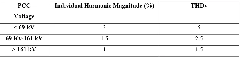
Table 2.2: Voltage Distortion Limits (in % of V1)
PCC
Voltage
Individual Harmonic Magnitude (%) THDv
≤ 69 kV 3 5
69 Kv-161 kV 1.5 2.5
7
Where: is Total Harmonic Distortion for voltage, is the fundamental voltage , is the harmonic voltage.
2.2.1.2 IEC 61000-3 Standard
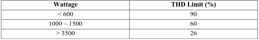
[image:19.595.106.532.424.491.2]The IEC 61000-3-2 describes the general requirements of harmonic current emissions and voltage fluctuations of electrical equipment with line currents lower than 16 A per phase. For the purpose o f harmonic current limitation, the standard divides electrical equipment into four classes. IEC 61000-3-4 is applied for line currents greater than 16 A per phase. The table 2.3 shows what the resulting current THD limit is for a 220 V device [11].
Table 2.3: THD Limits from IEC 61000-3-2 and 61000-3-4
Wattage THD Limit (%)
< 600 90
1000 – 1500 60
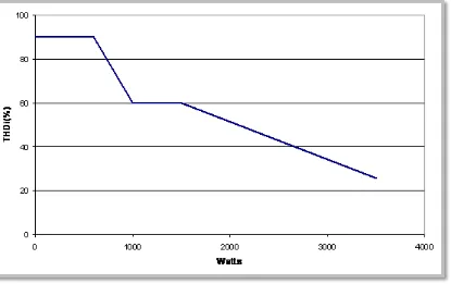
Figure 2.1 shows the same information contained in the table 2.3 but also shows the linear decline between intervals (i.e., between 600 W and 1000 W, and between 1500 W and 3500 W).
Figure 2.1: IEC Harmonic Limits as a Function of Wattage
Finally, the harmonic limits of IEC 61000-3 are based on product level at the terminals of end-user equipment while those of IEEE 519 are based on the interactions between facilities and the public distribution system. The main reason for these harmonic standards which are still evolving is to limit harmonic emissions from electronic equipment in order to protect other loads and components of the PS [10,11]
.
2.2.2 Harmonic Order
In the electrical system various type of harmonics are present which are given by their order. Harmonic order or harmonic number is a reference to the frequency of the harmonic component.
The order of harmonics [4] is given by equation (2.4).
9
Where = Integer value
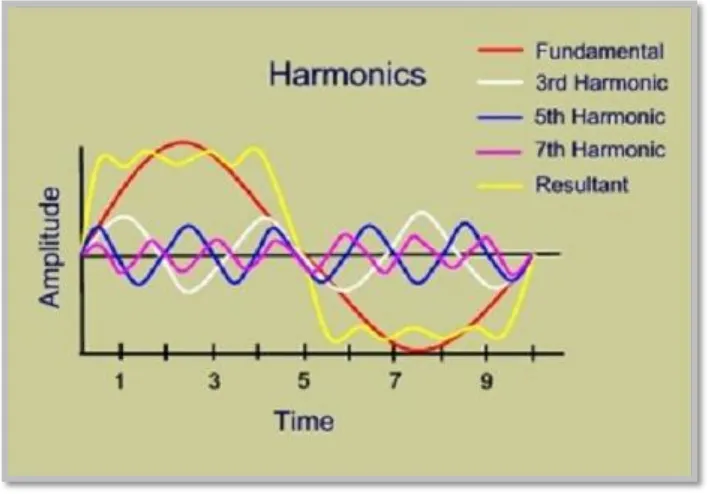
[image:21.595.141.496.238.485.2]So now if we had considered ideal condition that system has frequency of 50 Hz is with a peak value of 100 Amp current along the system. This 100 Amp value is also consider as one per unit. Likewise this per unit the harmonics would have same waveform of order of (1/3) (1/5) (1/7) of fundamental waveform or amplitude. Figure 2.2 shows the harmonic order is inverse to the amplitude of fundamental frequency.
Figure 2.2: Resultant waveform of system having 3rd, 5th and 7th harmonics
2.2.3 Source of Harmonic
The main harmonics sources can be divided into two categories. i. Non linear loads (i.e: speed drives ).
ii. Static power converters and transmission system level power electronic devices (i.e: switch-mode power supplies, voltage source converters).
the Uninterruptible power supplies (UPS) produces harmonics between the phases and produced the imbalanced system [4].
2.2.4 Effect of Harmonics
Harmonics are a major cause of power supply pollution lowering the power factor and increasing electrical losses. The effect of harmonic results in premature equipment failure and also cause of requirement of equipment of high rating The voltage distortion produced in the system is the major issue with the harmonics distribution. The electronics equipment used in the system usually generate harmonics more than one. In all type of harmonics the tripled harmonics are more severe example of triplet harmonics are 3rd 9th 15th [5].
These harmonics creates a big challenge for engineers because they poses more distortion in voltage. The effect of triplex harmonics come with overheating in wires, overheating in transformer units and also may become the cause of end user equipment failure. Triplex harmonics overheat the neutral conductor of 4 wire system. the neutral have generally no fundamental frequency or even harmonics but there may be existence of odd harmonics in system neutral conductor and when there is system consist of triplex harmonics it is become additive. These triplex frequency impact on the system can be understand by this way that even under balanced load condition on the account of triplex frequency neutral current magnitude reaches up to 1.75 times of average phase current [6]. Under above discussed case if the load of system increase may become cause of failure of insulation of neutral conductor which further result in the breakdown of transformers winding. The important and major effect of Harmonics is further discussed as:
2.2.4.1 Effect on Transformer
11
Harmonics produce addition losses in the transformer core as the higher frequency harmonic voltages set up hysteresis loops, which superimpose on the fundamental loop. Each loop represents higher magnetization power requirement and higher core losses.
Because of harmonics, the losses in conductor will increase. The resultant current will increase the distortion and is given by equation (2.5).
(2.5)
Where:
Overheating also can occur when there is resistive skin effect and winding proximity effect [1].
2.2.4.2 Effect on Capacitor bank
In industrial load where a lot of motors are used, we need to improve power factor. For this purpose we are connected capacitor banks near to the loads to improve it. Since harmonics create reactance as for capacitor reactance will increase as the frequency decrease. Therefore, the linear loads served from a common feeder, which also serves nonlinear loads of some other consumers, may become susceptible to harmonic distortion. Moreover, a consumer’s system which does not have harmonics can be subjected to harmonic pollution due to of other consumers in the system. The capacitors can be severely overloaded due to harmonics and can be damaged [7].
2.2.4.3 Neutral conductor over loading
phase cable. Under environment of harmonics the unbalanced current which is passed through the neutral produces a heat loss in the system which again affects the power quality of distribution system [4].
2.2.4.4 Effect on lines and cables
Harmonic distortion in a distribution system affects the system current and significantly. These increased rms currents produce additional heat losses in the system lines and cables Harmonic distortion in cables affect by increasing the dielectric stress in the cables. This stress is proportional to the voltage crest factor which represents the crest value of voltage waveform to rms value of waveform. The effect of this increased stress is such that, the cable useful life is shortened, causing faults, which ultimately increases the system capital and maintenance cost [6].
2.2.4.5 Thermal effect on rotating machine
Rotating machine are also affected by harmonics same as transformer. Resistance of rotating machine will go high if the frequency of system is high. For this if there is harmonic present in the system have a very rich current value which tends to produce a heat loss in the rotating machine . This overall heat loss will again affect its life and thus increase maintenance problems [8].
2.2.4.6 Undesired operation of fuse
In the environment of harmonic the RMS value of voltage and current may increase. This tendency will lead the problem of unexpected operation of fuse in capacitor banks or other arrangements which are used in the system to make operation of nonlinear load. If the fuse of one connected phase blown off then the other remaining fuse is in operation under a stress. In this condition the system become unbalanced and it will tends to produce the overvoltage in the system. To summarize above discussion it is concluded that, the following problems arise due to harmonics [8]. i) Equipment overheating
13
iv) Communications interference v) Fuse and breaker operation failure vi) Maintenance problem
2.3 Harmonic Reduction
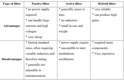
[image:25.595.110.531.335.609.2]There are various kinds of methods to reduce harmonics signal such as, oversize the neutral conductor, use separate neutral conductors and harmonic filters. Filters are designed to suppress system harmonics as well as to improve power factor. There are two common type of filters; passive filter and active filter. Table 2.4 shows comparison of different types of filters used for harmonic mitigation [4].
Table 2.4: Comparison of different types of filters
Type of filter Passive filter Active filter Hybrid filter
Advantages
* no power supply
required.
* can handle large
currents and high
voltages.
* very cheap
* generally easier to
tune.
* no inductors
* small in size and
weight
* very reliable
* can produce high
gains.
Disadvantages
* limited standard
sizes, often requiring
variable inductors and
therefore tuning.
* generally not
amenable to
miniaturization
* power supply require
* susceptible to inter
modulation,
oscillations
* required many
components
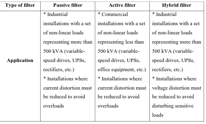
Type of filter Passive filter Active filter Hybrid filter
Application
* Industrial
installations with a set
of non-linear loads
representing more than
500 kVA
(variable-speed drives, UPSs,
rectifiers, etc.)
* Installations where
current distortion must
be reduced to avoid
overloads
* Commercial
installations with a set
of non-linear loads
representing less than
500 kVA
(variable-speed drives, UPSs,
office equipment, etc.)
* Installations where
current distortion must
be reduced to avoid
overloads
* Industrial
installations with a set
of non-linear loads
representing more than
500 kVA
(variable-speed drives, UPSs,
rectifiers, etc.)
* Installations where
voltage distortion must
be reduced to avoid
disturbing sensitive
loads
2.4 Passive filter
Power distribution system is designed to operate with sinusoidal voltage and current waveform at constant frequency. However, when non linear load like thyristor drives, converters and arc furnace are connected to the system, excessive harmonic currents are generated and this causes both current and voltage distortions. From the table 2.4, it is concluded that, the passive filter is the best way to eliminate the distortion in distribution power system [5].
[image:26.595.109.534.68.324.2]15
Figure 2.3: Low and High pass passive filters
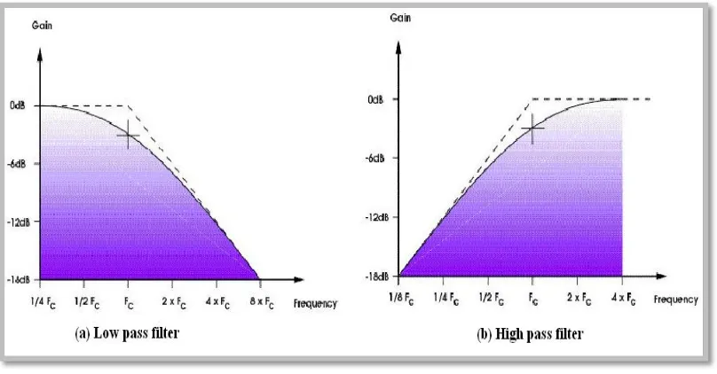
These filters pass low or high frequencies regardless of whether it is a fundamental or a nth harmonic (where n is any integer number). This means that these filters, known to be part of the class of passive filters, can be used to filter out higher order frequencies. These filters have an element known as a time constant which is often equal to the resistance multiplied by the capacitance “RC” connection. This time constant is called τ .
(2.6)
The cutoff frequencies of the filters are directly dependent on this constant. A simple equation to represent the cutoff frequencies for both the basic high and low pass RC filters is shown in Equation (2.7) [13].
Figure 2.4: Characteristic of cutoff frequency of Low and High Pass Filters
[image:28.595.137.500.389.597.2]Figure 2.5 shows the diagram of basic passive filter operation in power system network.
Figure 2.5: Block diagram of basic passive filter operation
17
2.4.1 Filter design constraints
There are various issues in the design of a passive filter for its proper functioning in harmonic reduction. The key issues are mentioned here:
a) Minimizing harmonic source current:
The prime objective of the filter design is to minimize the harmonic current in ac mains. This is ensured by minimizing the filter impedance at the harmonic frequencies so that the harmonic filter acts as a sink for the harmonic currents.
b) Minimizing fundamental current in passive filter:
To ensure that the installation of passive filter does not cause the system loading, the fundamental current in the passive filter is minimized by the maximizing the passive filter impedance at the fundamental frequency.
c) Environment and ageing effect:
The capacitors with metalized film construction lose capacitance as they age. Similarly the manufacturer tolerance of the harmonic filter reactor may result in tuned frequency higher than the nominal. An IEEE Standard 1531 [6] recommends that the passive filters are tuned at 6% below the rated frequency so that it will exhibit acceptable tuning at the end of its 20 year life.
2.4.2 Classification Of Passive Filters
Depending on the connection of different passive components, the passive filters can be broadly classified in two categories as given below.
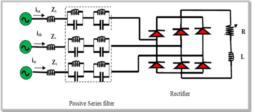
2.4.2.1 Passive Series Filter
flowing into ac mains. Here, the performance of the series filter is not much dependent on the source impedance. However, it results in reduction in dc bus voltage due to voltage drop across filter components.
Figure 2.6: Schematic diagram of passive series filter
2.4.2.2 Passive Shunt Filter
19
Figure 2.7: Schematic diagram of passive shunt filter
2.4.3 Type Of Passive Filters
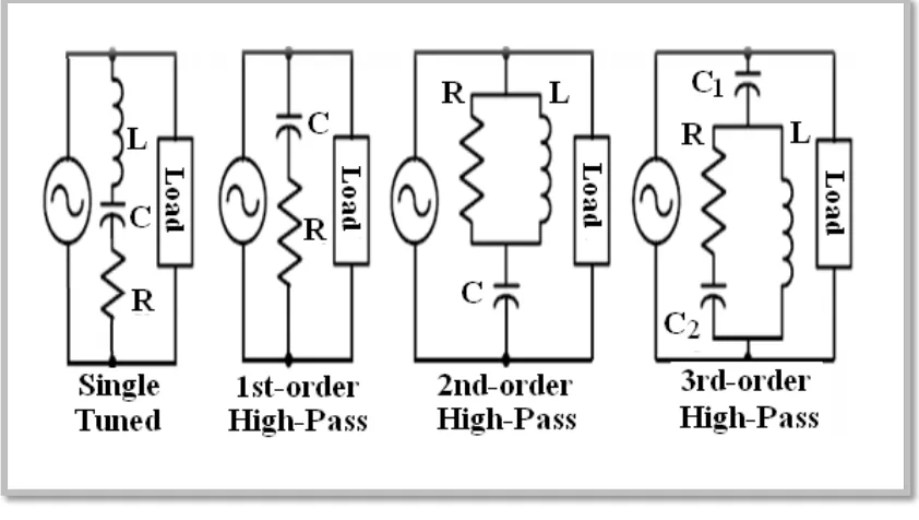
[image:31.595.113.534.416.654.2]There are several type of passive filters, the most commonly filter types as shown in figure 2.8 [7] .
Figure 2.8: Type of Passive Filter
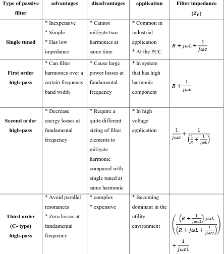
Table 2.5: Comparison of different types of passive filter
Type of passive
filter
advantages disadvantages application Filter impedance
( )
Single tuned
* Inexpensive
* Simple
* Has low
impedance
* Cannot
mitigate two
harmonics at
same time
* Common in
industrial
application
* At the PCC
First order
high-pass
* Can filter
harmonics over a
certain frequency
band width
* Cause large
power losses at
fundamental
frequency
* In system
that has high
harmonic component Second order high-pass * Decrease
energy losses at
fundamental
frequency
* Require a
quite different
sizing of filter
elements to
mitigate
harmonic
compared with
single tuned at
same harmonic
* In high
voltage application Third order (C- type) high-pass
* Avoid parallel
resonances
* Zero losses at
fundamental
frequency
* complex
* expensive
* Becoming
dominant in the
21
2.4.4 Compensation Principle of Passive Shunt Filters
This part will discuss about the compensation principle of passive shunt filters. Mainly single tuned filter are used as composite filter.
A passive shunt filter mainly consists of several LCR branches each tuned at a particular frequency. Figure 2.9 shows the equivalent circuit diagram of a passive tuned shunt filter. The compensation characteristics of a passive shunt filter is equated as [9].
[image:33.595.121.512.267.498.2]
Figure 2.9: Equivalent circuit diagram of passive tuned shunt filter.
Where is the impedance of parallel RLC filter, is the load impedance, is the line impedance, is the output voltage, is the input voltage, is the load current, is the filter current and is the input current. As it can be seen from equation (2.10), that the performance of parallel RLC filter greatly depends on the source impedance .
Moreover, if a filter is exactly tuned at a frequency of concern, then an upward shift in the tuned frequency results in a sharp increase in impedance as seen by the harmonic. The most common mechanisms that may cause filter detuning are: i. Capacitor fuse-blowing, which lowers the total capacitance, thereby raising
the frequency at the filter has been tuned.
ii. Manufacturing tolerances in both inductor as well as capacitor. iii. Temperature variations.
iv. System parameter variations.
23 2.5 Previous Research
[image:35.842.37.794.226.502.2]The table 2.6 below shows the summary of previous research.
Table 2.6 : Previous Research
Remark Tools and techniques Outcomes publication Title authors year Sr.No
* Need to reduce
the number of filters
due to cost because
the Author have
used five filters in
the test circuit.
* Need to reduce
firing angle in SCR
rectifier because it
is proportional with
Total harmonic
distortion. Matlab /
Simulink Presents a comparison
between diode rectifier
and SCR rectifier in six
pulse and twelve pulse
configuration. International Journal
of Scientific &
Engineering Research,
Volume 4, Issue 6,
June-2013 ISSN
2229-5518 Passive Filter For Harmonic
Mitigation Of Power Diode
Rectifier And SCR Rectifier Fed
Loads. C. L. Anooja ,
24 Remark Tools and techniques outcomes publication Title authors year Sr.No
Show the result of
power factor after
mitigates the effect. Matlab /
Simulink
And Genetic
Algorithm Presents a method capable
of designing passive
filters to reduce harmonic
distortion and correct the
power factor based on an
optimization technique. Journal of Theoretical
and Applied
Information
Technology
30th April 2014. Vol.
62 No.3
ISSN: 1992-8645
E-ISSN: 1817-3195 Design of passive filters for
reducing harmonic distortion
and correcting power factor in
two pulse rectifier systems using
optimization. D.M.RAN, et al
3102 [13]
Need to show Total
harmonic distortion
after getting the
result and the values
of active and
reactive power.
----Explanation about passive
and active methods of
power factor correction. Proceedings of the
14th International
Middle East Power
Systems Conference (MEPCON’10), Cairo
University, Egypt,
December 19-21,
2010, Paper ID 154. Review of Passive and Active
Circuits for Power Factor
Correction in Single Phase, Low
Power AC/DC Converters. H.Z.Azazi, et al
51
REFERENCES
1 Grady, W. Mack, and Surya Santoso. "Understanding power system harmonics." IEEE Power Engineering Review 21.11 (2001): 8-11.
2 Fujita, Hideaki, Takahiro Yamasaki, and Hirofumi Akagi. "A hybrid active filter for damping of harmonic resonance in industrial power systems." Power Electronics, IEEE Transactions on 15.2 (2000): 215-222.
3 Lin, Whei-Min, Tung-Sheng Zhan, and Ming-Tong Tsay. "Multiple-frequency three-phase load flow for harmonic analysis." Power Systems, IEEE Transactions on 19.2 (2004): 897-904.
4 Arrillaga, Jos, & Watson, N. R. Power system harmonics. John Wiley & Sons, Ltd, 2004.
5 Dugan, Roger C., Mark F. McGranaghan, and H. Wayne Beaty. "Electrical power systems quality." New York, NY: McGraw-Hill,| c1996 1 (1996).
6 IEEE Guide for Application and Specification of Harmonic Filters., IEEE Std. 1531-2003
7 Das, J. C. Power system analysis: short-circuit load flow and harmonics. CRC press, 2011.
9 Peng, Fang Z., Gui-Jia Su, and George Farquharson. "A series LC filter for harmonic compensation of ac drives." Power Electronics Specialists Conference, 1999. PESC 99. 30th Annual IEEE. Vol. 1. IEEE, 1999.
10 F II, I. "IEEE recommended practices and requirements for harmonic control in electrical power systems." (1993).
11 International Electrotechnical Commission. "Limits for harmonic current emissions (equipment input current≤ 16 A per phase)." (2004).
12 Anooja, C. L., and N. Leena. "Passive Filter For Harmonic Mitigation Of Power Diode Rectifier And SCR Rectifier Fed Loads."
13 DISTORTION, HARMONIC. "DESIGN OF PASSIVE FILTERS FOR REDUCING HARMONIC DISTORTION AND CORRECTING POWER
FACTOR IN TWO PULSE RECTIFIER SYSTEMS USING
OPTIMIZATION." Journal of Theoretical and Applied Information Technology 62.3 (2014).
14 Azazi, H. Z., et al. "Review of passive and active circuits for power factor correction in single phase, low power AC-DC converters." 14th International Middle East Power system Conference (MEPCON’10), Egypt. 2010.
15 Diwan, Seema P., H. P. Inamdar, and A. P. Vaidya. "Simulation Studies of Shunt Passive Harmonic Filters: Six Pulse Rectifier Load–Power Factor Improvement and Harmonic Control." ACEEE Int. J. on Electrical and Power Engineering 2.01 (2011): 1-6.
16 Srivastava, Kuldeep Kumar, Saquib Shakil, and Anand Vardhan Pandey. "Harmonics & Its Mitigation Technique by Passive Shunt Filter." International Journal of Soft Computing and Engineering (IJSCE) ISSN: 2231-2307.
53
18 Cho, Young-Sik, and Hanju Cha. "Single-tuned passive harmonic filter design considering variances of tuning and quality factor." Journal of International Council on Electrical Engineering 1.1 (2011): 7-13.
19 Bayindir, K. Çağatay, and Muammer Ermiş. "Understanding the modelling and
analysis of a shunt active power filter using
MATLAB/Simulink." International Journal of Electrical Engineering Education 43.3 (2006): 185-205.
22 Fujita, Hideaki, Takahiro Yamasaki, and Hirofumi Akagi. "A hybrid active filter for damping of harmonic resonance in industrial power systems." Power Electronics, IEEE Transactions on 15.2 (2000): 215-222.
21 Memon, Zubair Ahmed, Mohammad Aslam Uquaili, and Mukhtiar Ali Unar. "Harmonics mitigation of industrial power system using passive filters." Mehran University Research Journal of Engineering and Technology 31.2 (2012): 355-360.
22 Dastfan, Ali, Hossain Yassami, and Mohammad Reza Rafiei. "Optimum Design of Passive Harmonic Filter by Using Game Theory Concepts." Intelligent Systems in Electrical Engineering 4.4 (2014).
23 Cho, Young-Sik, and Hanju Cha. "A single-tuned passive harmonic filter design using transfer function approach for industrial process application." International Journal of Mechatronics and Automation 1.2 (2011): 90-96.
24 Buła, Dawid, and Marian Pasko. "Hybrid power filter with single tuned passive filter-dynamical properties." Nonsinusoidal Currents and Compensation (ISNCC), 2010 International School on. IEEE, 2010.