Journal of Physics: Conference Series
PAPER • OPEN ACCESS
Effects of fractal grid on spray characteristics and
flame development in burner combustion
To cite this article: S H Amirnordin et al 2017 J. Phys.: Conf. Ser. 822 012046
View the article online for updates and enhancements.
Related content
Circle grid fractal plate as a turbulent generator for premixed flame: an overview M F Othman, B Manshoor and A Khalid
-Thermography of flame during diesel fuel combustion with steam gasification I S Anufriev, S S Arsentyev, M V Agafontsev et al.
-Interaction of turblence and chemistry in a low-swirl burner
J B Bell, R K Cheng, M S Day et al.
Effects of fractal grid on spray characteristics and flame
development in burner combustion
S H Amirnordin1, A Khalid1, M Suardi1, B Manshoor and M F Hushim 1 Combustion Research Group (CRG), Centre for Energy and Industrial Environment
Studies (CEIES), Faculty of Mechanical and Manufacturing Engineering, Universiti Tun Hussein Onn Malaysia, 86400 Parit Raja, Batu Pahat, Johor, Malaysia.
E-mail: amirk@uthm.edu.my
Abstract. Turbulence generator plays an important role in enhancing turbulence in combustion and determining the flame characteristics in burner combustion. This research demonstrated the effect of a fractal grid on the spray and flame characteristics in burner combustion. Three geometrical configurations of fractal grid were investigated with different equivalence ratios of 0.5–1.0. The images were captured using direct photographic method. The characteristics of the spray and flame were studied, including the length, angle, and area. The results from this fractal grid were compared with the swirl. The results showed that the fractal geometry and ratio of air-to-fuel mixture affected the performance of the burner. The correct combination of fractal geometry and air-to-fuel ratio resulted in complete combustion and improved the overall performance of the burner.
1. Introduction
Diesel is a natural resource that is consumed heavily in the world because of the increasing demand for energy. It can be used in numerous applications, such as fuel in automotive and burner systems. Therefore, the continuous improvement of controlled diesel combustion is urgently required [1].
The generation of turbulence from fractal grids has attracted many researchers [2-6]. Krogstad [5] investigated turbulence from fractal grids generated by wind tunnels. Measurements using hot wire and laser Doppler anemometry revealed the strong dependency of turbulence on the grid geometry. The advantages of fractal grid were further studied by Soulopolous et al. [6]. The fractal grid was used to generate turbulence in the premixed flame. The parameters of the grid were blockage ratio, effective mesh size, and perimeter. Results illustrated the advantages of fractal grids. Under the same heat release and downstream distance, fractal grids created intense turbulence and changed the combustion regime. Compared with regular grids, fractal grids exhibited intense turbulence at a given downstream in which the flame angle and turbulent flame speed increased by 50%. Physically, the curvature and flame brush thickness presented large corrugations and intense burning.
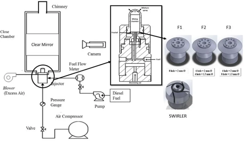
In this research, the effects of fractal grids of different geometry were investigated, focusing on the behaviour of the flame. A closed chamber system (Figure 1) was used with direct photographic methods to study the angle, length, and area of the flame.
2. Experimental Setup
A schematic of the experiment is presented in Figure 1 [7]. The main component was an atomizer with
Fifteenth Asian Congress of Fluid Mechanics (15ACFM) IOP Publishing
IOP Conf. Series: Journal of Physics: Conf. Series 822(2017) 012046 doi:10.1088/1742-6596/822/1/012046
International Conference on Recent Trends in Physics 2016 (ICRTP2016) IOP Publishing
was for incoming fuel. Excess air was supplied to assist in combustion in the closed chamber. The spray and flame video images were captured in color using Sony FDA-EV1S. The images were analyzed using GOM Player and ImageJ software.
Table 1 shows the properties of diesel used in this experiment . The density of the diesel fuel is 0.83374 g/cm3. The details of the experimental equipment and testing conditions are presented in
Table 2. The primary air pressure Pi was constant at 0.1 MPa, which corresponded with the primary air
flow rate of 40 L/min. The adjustable parameters were fuel mass flow rate and secondary air mass flow rate. Diesel was sprayed via the 8-hole atomizer with a diameter of 1 mm using three different fractal geometries. The following fractal grids were fabricated and tested in this system: Fractal 1 with eight holes of 2 mm, Fractal 2 with six holes of 2 mm and four holes of 1.5 mm; and Fractal 3 with four holes of 2 mm and eight holes of 1.5 mm.
3. Result and Discussion
Figure 2 shows the spray formation of Fractal 1 at the equivalence ratio of 0.6 to 0.9 (lean) and 1.0 (stoichiometry). The diesel fuel was sprayed upward as the mixtures were directed into the injector. As time increased by 0.03 s for each image, spray penetration rose. Analysis of spray penetration (at 0.12 s when the penetration peaked) showed that the penetration also increased as the equivalence ratio increased (Table 3). The highest penetration was achieved at stoichiometric conditions (equivalence ratio of 1.0) of 587 mm.
Figure 3 shows the flame images of Fractal 1 developed from 0 s to 0.12 s at different equivalence ratios. An increase in the air–fuel ratio affected flame stability and burner combustion. At a high equivalence ratio, the flame area increased because of the increment of the air–fuel ratio. Table 3 indicates that the highest flame area was 317,585 mm2 under stoichiometric conditions. The image of
[image:3.595.88.506.163.405.2]the flame area obtained from ImageJ is highlighted in Figure 4.
Figure 1. Schematic diagram of experimental setup
2
Fifteenth Asian Congress of Fluid Mechanics (15ACFM) IOP Publishing
Table 3. Spray penetration and flame area of Fractal 1
Properties Value
Density (g/cm3) 0.83374
Kinematic viscosity
(Cp) 3
Flash point (°c) 80
Water content (%) 0.00796
Acid value
(mgKOH/g) 0.423
Air Compressor
Model QUASA HDC-D3050 Capacity, L/min 200 Pressure, kg/cm2 8
Water Pump
Model SFDP1-014-080-22-Seaflo
Voltage, V 12
Flow rate, L/min 5.1
Fuel Pump
Model CNY-3805
Pressure, bar 3 Flow rate, L/hr 100
DC Voltage Regulator
Model Teletron TC-1206A Current, A 64 (max)
Operating condition
Air Pressure, MPa 0.1 Air Density, kg/m3 1.16 Ambient Temperature,
K
300
Equivalence Ratio 0.5 - 1.0
Table 1. Properties of diesel fuel Table 2. Equipment and experimental condition [7]
0 . 0 .
0.8
0.9
1.0
Equivalence ratio 0.6 0.7 0.8 0.9 1.0
Spray penetration
(mm) 310 407 502 547 587
Flame area
[image:4.595.79.517.117.535.2]2 118,669 170,264 183,295 260,237 317,585
Figure 2. Spray development using Fractal 1 (8 holes of ∅2 mm)
Figure 3. Flame development using Fractal 1 (8 holes of ∅2 mm)
Fifteenth Asian Congress of Fluid Mechanics (15ACFM) IOP Publishing
[image:4.595.78.515.374.559.2]Figure 4. Flame area (indicated by the white area) of an image from Fractal 1 at equivalence ratio 1.0
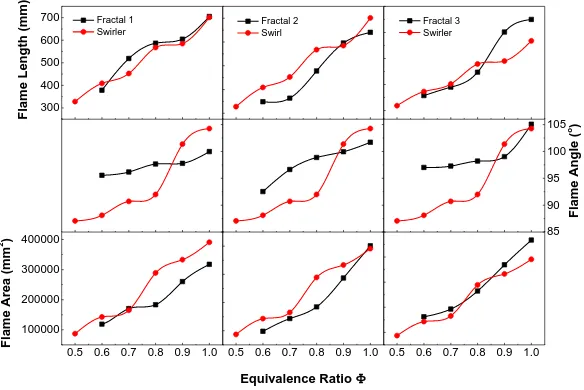
The flame characteristics consisted of the flame length, flame angle, and flame area. Figure 5 exhibits the characteristics of the three fractals. In general, the flame length, angle, and area showed an increasing trend with the equivalence ratio for each type of fractal. This trend indicated the strong relation between the air–fuel ratio and burner combustion.
For Fractal 1, the flame length was higher compared with the swirl. However, the swirl showed a larger flame area and angle as the equivalence ratio approached stoichiometric conditions (0.8, 0.9, and 1.0). For Fractal 2, the swirl showed a higher flame length and flame area. Fractal 3 exhibited higher flame length, flame angle, and flame area compared with the swirl. Therefore, Fractal 3 displayed potential as a turbulence generator in the burner system with better flame characteristics compared with the swirl.
300 400 500 600 700
0.5 0.6 0.7 0.8 0.9 1.0 100000
200000 300000 400000
0.5 0.6 0.7 0.8 0.9 1.0
85 90 95 100 105
0.5 0.6 0.7 0.8 0.9 1.0
Flame Leng
th
(m
m)
Fractal 1 Swirler
Equivalence Ratio
Flame Are
a
(mm
2)
Fractal 2 Swirl
Fractal 3 Swirler
Flame Ang
le
(
[image:5.595.150.442.400.595.2]o)
Figure 5. Flame characteristics of each Fractal
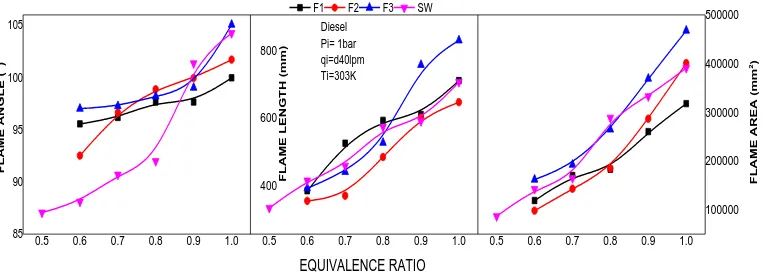
Figure 6 shows the influence of fractal geometry on the flame characteristics in the burner. The changes in the flame length, angle, and area of the flame were also influenced by the equivalence ratio. The equivalence ratio of 1.0 produced the largest flame angle, highest flame length, and highest flame area. The figure also indicated that Fractal 3 demonstrated the highest flame length, flame angle, and flame area, especially at the equivalence ratios of 0.8, 0.9, and 1.0. Therefore, Fractal 3 at the equivalence ratio of 1.0 resulted in the highest combustion performance.
4
Fifteenth Asian Congress of Fluid Mechanics (15ACFM) IOP Publishing
0.5 0.6 0.7 0.8 0.9 1.0 85 90 95 100 105
0.5 0.6 0.7 0.8 0.9 1.0
400 600 800
0.5 0.6 0.7 0.8 0.9 1.0
100000 200000 300000 400000 500000 F L A M E A N G L E ( O)
F1 F2 F3 SW
[image:6.595.109.491.117.253.2]F L A M E L E N G T H ( m m ) EQUIVALENCE RATIO Diesel Pi= 1bar qi=d40lpm Ti=303K F L A M E A R E A ( mm 2)
Figure 6. Flame characteristics of all Fractals
4. Conclusion
A fundamental study on the effect of fractal grid in the rapid mixing injector using diesel fuel in the burner system was conducted. Discussion focused on the relation between the equivalence ratio and flame development during the burning process. Results are summarized as follows:
1. A high equivalence ratio will result in a long flame length, wide flame angle, and large flame area. The flame length will affect the flame area. As the equivalence ratio increased, the intensity of the flame also increased.
2. The results of the flame length were dependent on the fractal geometry. The fractal grid significantly influenced combustion. Fractal 3 was found to improve combustion compared with the other fractals and swirl.
Acknowledgements
The authors would like to thank the Ministry of Higher Education Malaysia for supporting this research under Exploratory Research Grant Scheme (ERGS) Vot E032 and also partly sponsored by the Centre for Graduate Studies UTHM.
References
[1] Mishra D 2008 Fundamentals of Combustion (New Delhi: Prentice-Hall of India Private Ltd) [2] Seoud RE and Vassilicos JC 2007 Dissipation and decay of fractal-generated turbulence Physics of
Fluids19(10):105108
[3] Verbeek AA, Bouten TW, Stoffels GG, Geurts BJ and van der Meer TH 2015 Fractal turbulence enhancing low-swirl combustion Combustion and Flame 162(1):129-43
[4] Othman MF, Manshoor B and Khalid A 2013 Circle grid fractal plate as a turbulent generator for premixed flame: an overview In IOP Conference Series: Materials Science and Engineering (Vol. 50, No. 1, p. 012050) IOP Publishing
[5] Krogstad P 2012 Turbulent decay in the near field of multi-scale and conventional grids International Journal of Heat and Fluid Flow35 102-8
[6] Soulopoulos N, Kerl J, Sponfeldner T, Beyrau F, Hardalupas Y, Taylor AM and Vassilicos JC 2013 Turbulent premixed flames on fractal-grid-generated turbulence Fluid Dynamics Research
45(6):061404
[7] Khalid A, Amirnordin SH, Lambosi L, Manshoor B, Sies MF and Salleh H 2014 Spray characteristic of diesel-water injector for burner system Advanced Materials Research845 pp 66-70
Fifteenth Asian Congress of Fluid Mechanics (15ACFM) IOP Publishing