Axial Compression Behaviour of Wallettes Gonstructed Using
Wood-Wool
Cement
Gomposite
Panel
Mohammad Soffi Md Nohl'^ ,ZakiahAhmad2'b and
Azmi
lbrahim3'"
lFaculty of Civil and Environmental Engineering, Universiti Tun Hussein Onn Malaysia, 86400 Parit
Raja, Batu Pahat, Johor, Malaysia
2lnstitute of lnfrastructure and Sustainable Engineering Management, Universiti Teknologi Mara,
40450 Shah Alam, Selangor, Malaysia
3Faculty
of Civil Engineering, Universiti Teknologi Mara, 40450 Shah Alam, Selangor, Malaysia
"soffi @ uth m. ed u. my,
D
zaki ah @sala m. ed u. my, " azmii7 1 6 @yah oo. com
*Corresponding author
Keywords:
Structural behaviour, Wallettes, Wood-Woolcement
compositepanel
(\M|/CP),Mechanical properties, Axial compression.
Abstract. This paper reports on the investigation of the structural behavior of wallettes made from
wood-wool cement composite panel (WWCP).
Initially,
a seriesof
experimental test were carriedout
to
investigate the mechanical propertiesof
WWCP namely density, bending properties (MORand MOE), compressive strength and tensile strength
for
two thicknessesof
WWCP (50 mm and100 mm). Then, the axial compression capacity of WWCP was investigated using wallettes. In the
fabrication
of
wallettes, there aretwo
typesof
panel arrangement considered and denoted asWl
and W2. For
Wl,
100 mm thick WWCP was used and cut into sizeof
300 mm width and 600 mmlength. The cut panels were then stacked vertically (two layer)
in
running bond patternto
form a600 mm
x
600 mm wallettes. The top and bottom panels were connected togetherwith
10 mm thickmortar paste and three
vertical
steel bars were inserted between panels.In
additionto
this,
anenhancement has been made by fixed two U-Nail at the connection area on each side of wallettes.
For W2, a new panel arrangement technique has been proposed by integrating two layers of 50 mm
thickness of WWCP (cut into size of 300 mm width and 600 mm length)
with
different orientationof panel arrangement to form a 600 mm
x
600 mm wallettes. The front side of the panels has beenarranged in the longitudinal direction, whereas back side in transverse direction. The front and back
side panels were bonded together using either adhesive or mortar
mix with
different thicknesses toform approximately 100 mm
(+
15 mm) thickwall.
For mechanical propertiesof
WWCP,it
wasfound that, the strength properties of the panel decreases
with
the increased in panel thickness. Forthe axial
compressiontest
of
wallettes,the
results showedthat,
a
new
proposedof
panelarrangement technique
with
mortarmix
significantly improved the stability aswell
as increasedload canying capacity of wallettes.
Introduction
Wood and
wood-based productsis
an
importantbuilding material
madefrom
renewablematerials,
lightweight, and
easyto
processand
fabricateand
it
is
widely
availablefor
theconstruction industry. As wood production requires less energy and lower carbon emissions from
the
forestry andwood
processing,it
canbe
a
low-energybuilding
materials and suitable tosubstitute other materials such as concrete and steel [1]. In the last two decades, the production of a
variety
of
wood based productsfor
building applications has shown that woody materials can beused and enhanced features for construction materials [2,3].
Wood-wool cement composite panel (WWCP) is one of the wood-based products made from a
mixture of wood-wool, cement and water. Wood-wool is the main compound of wood-wool cement
composite panels (WWCP) that acts as a reinforcing agent
to
be coateduniformly
with
cementpasti before it was pressed to form a panel with a density in the range of 300 kg/m' - 500 kg/m3 [2].
Advanced Materials
Research
Vol.
1051Wood-wool
is
producedby
shreddinga
log
usinga
professional shredding machine and hasdifferent sizes up to 3.5 mm [4].
Previously, the use
of
WWCPwithin
the construction industry waslimited
to
non-structuralapplications
[3]
and therefore most of the research conducted has focused on material propertiesof
WWCP.
For
example, Sempleand
Evans[5]
studiedon the
effectsof
hearthwoodon
themechanical properties of wood-wool cement boards manufactured from Radiata Pine, Cabangon et
al.
[6]
studied on the effectof
strand orientation asto
improving the flexural propertiesof
wood-wool cement board in the Philipine. Ahmad
et
al.[4],
studied on mechanical propertiesof
wood-wool
cement composite board (WWCCB) at differencesof
wood-wool size and board thicknessmade from Malaysian fast grown timber species known as Kelampayan. In another study, Ashori et
al. l2l,
experimentally investigatedthe
mechanical propertiesof
wood-wool
cement board(WWCB) made from two species of wood namely Eucalyptus and Poplar and the results indicated
that, the of mechanical properties of the board have been found to satisfy the minimum requirement
specified in the ISO standard.
Recently,
in
Malaysia,the
acceptancein
using wood-wool cement composite panels as wallelements for buildings have been increased particularly for constructing low cost housing. This due
to the wood-wool cement composite panel has many potential advantages such as light weight, low
cost, the
ability of
thermal and sound insulation, resistantto
biological degradation and speed upconstruction
time.
Despiteits
many advantages, designers and contractors, aswell
as buildingowners are
still
hesitantto
usethis
material as there wasstill a
lack
of
design standards andguidelines
Ul.
Currently,
the
design
and
construction methodsusing WWCP
still
followconventional construction methods as the study was conducted on the structural behavior
of
thiswall system is
still
limited.Therefore,
in
this
paper, the potentialityof
a
newwall
system constructed using wood-woolcement composite panel
is
investigatedin
orderto
gain better understandingof
the
structuralperformance of the wall when subjected to loads.
Materials and Methods
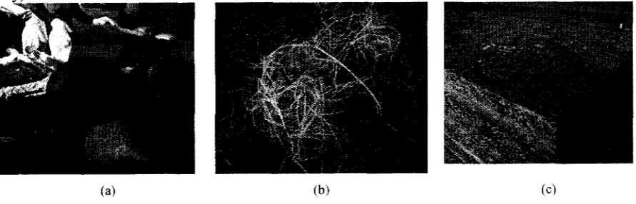
Wood-wool Cement Composite Panel (WWCP)
WWCP used in this study is made from wood-wool that has been shredded from a cut of local fast
grown timber species known as Kelampayan
(Fig.la).
The typical wood-wool strands used in themanufacturing of WWCP are approximately 3.5 mm wide and 0.5 mm thick
with
lengths up to 400-
500 mm as shownin
Fig.
lb.
WWCPis
factory made and manufacturedby
Duralite(M)
Sdn.Bhd., produced
in
standard panel sizeof
600 mm width, 2400 mmin
length and varying from 25 [image:2.593.71.517.574.717.2]mm
to
100 mm thicknesses(Fig.
1c). There are two typesof
panel thicknesses considered in thisFigure l. (a) Shredding a log (b) Wood-wool (c) Wood-wool cement composite panel (WWCP)
Test Specimen
The experimental activities carried
out
in
thiswork
dealwith
mechanical propertiesof
WWCP,flexural
and compressive strenglhof
hardened mortar and behaviorof
prefabricated wallettes671
constructed using WWCP subjected to axial compression load. For the mechanical properties test
of
WWCP,
atotal
of
50 specimens was preparedfrom
50 mm and 100 mm thicknessesof
WWCP.The details
of
specimens for the mechanical properties test is shown in Table 1. For the hardenedmortar
test,3
specimensof
40 mm square and 160 mm lengthfor
each7,28
and 56 days werecarried
out.
For the axial compression behavior test, a totalof
18 wallettes had been fabricated withdifferent panel thickness, panel arrangement and
joint
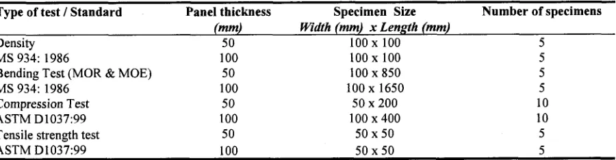
techniques.Table I . Specimen details for mechanical properties test of WWCP Type oftest / Standard Panel thickness Specimen Size
(mm)
Width (mm) x Length (mm)Number of specimens
Density MS 934: 1986
Bending Test (MOR & MOE) MS 934: 1986
Compression Test ASTM D1037:99 Tensile strength test ASTM D1037:99
50 100
50 100
50 100
50 100
100 x 100 100 x 100 100 x 850 100 x 1650
50 x 200 100 x 400
50x50 50x50
5 5 5
)
10 10 5 5
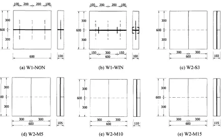
Fabrication of Walleffes
There are two types
of
panel arrangement considered in the fabricationof
wallettes which areWl
and W2. For
Wl,
the 100 mm thick WWCP was used and cut into sizeof
300 mm width and 600mm
length.The
cut
panels werethen
stackedvertically
(two
layer)
in
running bond patternsimilarly as a
brick
laying processto
form a 600 mmx
600 mm wallettes.
The top and bottompanels were connected together
with
10 mmthick
mortar paste andto
hold
the panelsin
theirposition, the three vertical steel bars were inserted between panels. This wallettes specimen was
referred to
Wl-NON
(Fig.2a).
Meanwhile,for
WI-WIN
an enhancement has been made by fixedtwo U-Nail
at the connection area on each sidein
orderto
increase the stabilityof
this typeof
wallettes as shown in Fig. 2b. For W2, a new panel arrangement technique has been proposed as to
improve stability and increased load carrying capacities of the wallettes. The idea is by integrating
two layers
of
50 mm thickness of wood-wool panels (cut into sizeof
300 mm width and 600 mmlength)
with
different orientation of panel affangement to form a 600 mmx
600 mm wallettes. Thefront
sideof
the
panels has been arrangedin
the
longitudinal direction, whereas back side intransverse direction. The front and back sides
ofthe
panels, then, have been bonded together usingadhesive
to form
100mm
(+
15mm) thick
wall. In
this
type,the
wallettes can be seen as asandwich panel where the panels are the covering sheets and the adhesive is the core. For wallettes
W2-S3, Sikadur 30 has been used as an adhesive
with
3 mm thick glue line (Fig. 2c) whereasW2-M5,
W2-M10 and W2-M15 the EmacoRl
mortarmix with
thicknessesof
5mm,
l0
mm and 15mm respectively have been used as an adhesive (Fig. 2d, 2e and
2f).
These two types of adhesive,Sikadur
30
and EmacoRl
mortar have been suppliedby
Sika Malaysia Sdn.Bhd.
and BASFMalaysia Sdn. Bhd. respectively.
Testing Set-up and Procedures
In
the mechanical properties test, the specimens werecut
into
desired sizes, then the test wascarried out
in
accordancewith
standards that have been described earlierin
Table 1. This includeddensity test, determination
of
bending properties (MOR andMOE),
compression test and tensilestrength test (internal bond). The
flexural
and compressive strength of EMACORl
mortar test wascarried out in accordance to BS
EN l0l5-1
l:1999 [ 10] as to establish the contribution of mortar tothe overall stiffness and strength of the wallettes. This test was conducted on
7,28
and 56 days ageof
hardened mortar.All
the specimens were made from the same sampleof
mortarmix
used fortbbricating the wallettes.
In
theaxial
compressionload
test,a
three replicatesof
each typeof
wallettes were tested under axial compression load after 28 days
of
fabrication. The wallettes werecarefully placed on
top
of
steel beams under the middleof
a steel spreader beam which directlyconnected
to
the
250kN
hydraulicjack. The
10mm thick
plywood was placed between thespreader beam and specimen as
to
ensure the loadis uniformly
distributedto
the wallettes. The [image:3.593.70.520.192.309.2]Advanced Materials
Research
Vol.
1051 673displacement and
LVDT 2
and 3 are used to measure the horizontal displacement of the wallettes asshown in Fig. 3. The position and straightness of the specimens were checked using a spirit level to
avoid load eccentricities. The load was then applied
at a
uniform rateof
0.005 mm/minup
tofailure. The failure load, maximum displacement at peak and the failure mode was observed.
il
Ftl
t_l
to0
il
300
uio+
,1.
Lt
n
ill
fi'l
lrl
L.J
100
itos, ri
ll'
'i'
lff
F;
'i{
100, 200 200 100
f+-.-f. -f*-.1
I
1
+ :
il
I
600
f.--(a) Wl-NoN
100 200 200 100
-'r.-..- -T -r 'r
tl l
150 300
150[-r
sooT ]
(b)
wl-wIN
103
1,,.1
i.t
i
'i'1
390
I
f|E
l-i
600+Ul
r'i'
1,,0,
(c) W2-S3
IJ;
u?o I
300
(d) w2-M5
, 300 300
t
=60
[image:4.593.69.510.143.417.2] [image:4.593.100.486.462.625.2]|--(e) W2-Ml0 (e) W2-M15
Figure 2. Configuration of wallettes fabricated using wood-wool cement composite panel (All units in millimeters)
Sor@der Beam
--10 DD
thk.--prywffi - LVDT2&3
Specimen
sted
Bam-.-(a) Illustrated testing
set-up
(b) Actual testing setFigure 3. Axial compression load testing set-up of WWCP wallettes
Results and Discussions
Mechanical Properties of
WWCP
The mechanical properties results presented in this section are rnainly to establish the current state
of
knowledge regarding the characteristicsof
WWCP before structural testing on behaviouralof
wall
constructed using WWCP have been further carried out. The results of mechanical propertiesare shown
in
Table 2. The results showed that, the thickness of the panel aswell
as panel densityhad a significant effect on the mechanical properties of the panels. These significant are similar to
the findings as reported by Ahmad et al.
[4]
where the densityof
WWCP is the best indicator in SO mh&0 mm
predicting the strength properties of the panels.
It
can be seen that, the mean density of 50 mm panelis recorded 20 %higher than 100 mm panel. These were followed by the bending properties (MOR
and MOE), compressive strength and tensile strength of the panels where the strength of the panel decreased with an increase of panel thickness. Ashori et al. [2) reported that, the porosity of thicker
panel is the major contribution to the decreasing
of
panel strength. The increasingof
wood-woolcontent tends
to
reduce the interfacial areaof
contactwithin
the cementmatrix
and wood-woolcausing lower bond strength. Furthermore,
it
was observed that, the settlement of matrix during thesetting time
of
the panel as the main factorof
increasein
porosityof
100 mm composite panels.Despite
of
reductionin
strength properties of WWCP, according to German Standard(DIN
1101)the densities
of
50 mm and 100 mm panels werestill
in the rangeof
low density panel (250kd-'
to 600 kg/m3) [4,11]. Beside of that, the bending and compressive strength calculated in this study
[image:5.593.62.520.274.362.2]were higher than the minimum requirement specified in that standard [11].
Table 2. Mechanical properties of wood-wool cement composite panel
Panel Thickness (mm) Density (kg/m3) Bending Properties
MOR
MOE(N/mm2)
(N/mm2)Compressive Strength
Perpendicular
Parallel(N/mm2)
(N/mm2)Tensile Strength (N/mm2)
Mean SD
Mean
SD Mean
SD Mean Mean SD50 100
328 272
r4.5
l.l5
6.4
0.400.r7 444
41.s0.05 239
29.60.84
0.0590.30
0.0080.041 0.060
0.0100.034 0.018
0.005 1.000.30
Flexural and Compressive Strength of Hardened
Mortar
The results of flexural and compressive strength of hardened mortar are shown in Table 3.
It
can beseen that, the EMACO
Rl
mortar strengths were drastically achieved its early strength at7
days.This is a very quick strength gain as recommended by the manufacturer where compressive strength
at day 7 shou^ld be greater than ?0
N/mm'
[12]. Th"e strengths of mortar were further increased from11.60 N/mm"
to
12.44N/mm'
and23.90N/mm'to
26.02N/mm"
for
flexural and compressivestrengths respectively at
28
days and achieved the target compressive strength of 25 N/mm".At
56 days, the compressive strength of mortar was increased gradually to 27.57 N/mm'.Table 3 . Strength properties of hardened mortar
Age of
specimen (Davs)
No. of specimen
Flexurul
test
Compression testFlexural strength (N/mm')
Mean
^SDCompressive strength (N/mm2)
Mean
SD736
2836
5636
l 1.60 12.44 14.00 0.28 0.1I 0.53 23.90 26.02 27.57 t.74 0.43 0.66
Axial
Compression Behaviour of WallettesThe axial compressive strength of wallettes obtained from this study is a useful guide
in
order todetermine the load carrying capacity
of
wallettes andto
investigate the behaviourof
wall
undercompression load.
A
summary of maximum load, displacement at peak load and failure descriptionof
each type wallettes are presentedin
Table4.
Load-displacement curves selectedfrom
eachwallettes specimen also presented in Fig. 4.
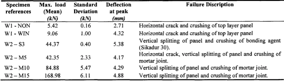
Table 4. Maximum load, deflection and failure mode of wallettes under axial compression load
Specimen Max.
load
Standardreferences
(Mean)
Deviation(kN)
(kr9Deflection at peak
(mm)
Failure Discription
wl
- NoNwl
- wINw2-s3
w2-M5
w2-Ml0
w2-M15 5.42 9.06 44.37 42.35 84.88 168.98 0.16 1.00 0.402-J 5
5.47 6.1 I
2.71 4.32 5.38 4.t7 4.29 4.88
Horizontal crack and crushing oftop layer panel Horizontal uack and crushing of top layer panel
Vertical splitting of panel and crushing of bonding agent (Sikadur 30).
Horizontal crack, vertical splitting of panel and crushing of
mortar joint.
[image:5.593.58.518.653.787.2]Advanced Materials
Research
Vol.
1051 675The experimental results
of
Wl
indicated that,the axial
deformationof
wallettes increasedlinearly with the applied load up to maximum load. The maximum loads recorded were 5.42 kN for
WI-NON
and 9.06kN for
WI-WIN. It
can be seen that, the additionof U-Nail
at the connectionpart significantly increased the load carrying capacity
of
this typeof
wallettes. The load carryingcapacity
of WI-WIN
(walletteswith
U-Nail)
is
1.7 higher than walletteswithout
U-Nail
(Wl-NON).
It
was observed that, the failure mechanism ofWl
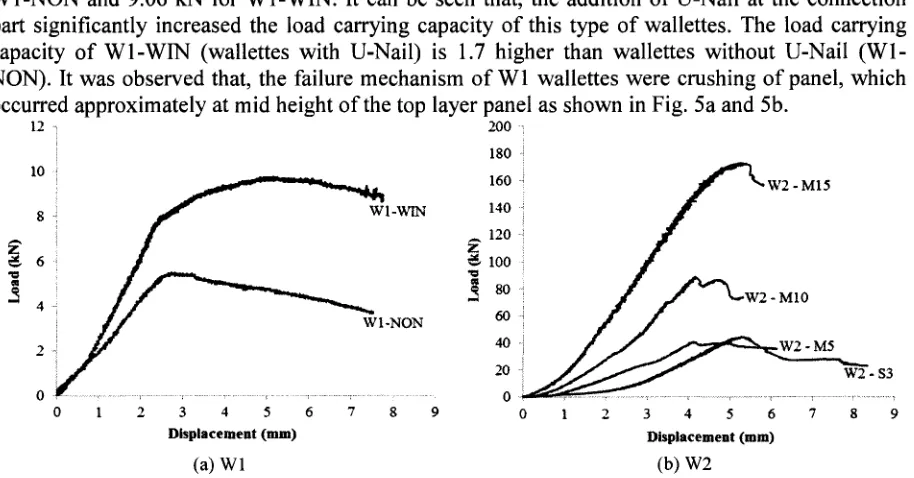
walleffes were crushing of panel, whichoccurred approximately at mid height of the top layer panel as shown in Fig. 5a and 5b.
300 :
180 .l
160 -l
l4o j
^120i zt €lool
{
soiw1-NON 60
40 afi 0
23436
Dlsplrccment (mn) (a) Wl
3456
[image:6.593.66.523.125.364.2]Dbplacemert (mm) (b) w2
Figure 4. Load-displacement curves of selected each wallettes type under axial compression load.
For W2, the new proposed panel arrangement technique was seen performing better in term
of
axial load carrying capacity compared against
Wl.
Wallettes W2-M15 was recorded as a highestcompression load carrying capacity among the tested wallettes. W2-M15 failed at an applied load
of
168.98 kN while W2-M10 failed at an applied load
of
84.88 kN. For W2-M5, the maximum loadwas recorded approximately identical to W2-S3
with
alittle
difference in the failure load of 42.35kN
and 44.37kN.
It
is evident that, the usedof
mortarin
different thicknesses as an adhesive tobond
two
layersof
50mm
panels were significantly contributingto
increase compression loadcapacity of W2 wallettes
[3].
It
can be seen that, the load increased approximately 100 Yofor eachincrement
of
5
mm
mortar
thickness. Previoustest has
shownthe
importanceof
mortar tocompressive strength
of
wallettes. Oliveira and Hanai[14]
reported that, the applicationof
twotypes
of
mortar (weak and strong morlar)for
wallettes overlay increased20
yoin
compressivestrength of wallettes. In terms of the failure mode, it was observed that, the failure mechanism was
similar
for all W2
wallettes specimens. When loading was continued the panelin
compressionstarted to split out vertically near to the mortar
joint
which cause the de-bondingof
panel sheet asshown
in
Fig. 5c. The load was then further increaseduntil
to the overall failure was occulred by(a) Crushing failure of Wl-NON (b) Crushing failure of WI-WIN (c) Splitting of panels of W2-Ml5
crushins the bondin Sikadur 30 and mortar
[image:6.593.64.519.607.745.2]Conclusion
The conclusions from this study can be drawn as follows:
.
The both panels (50 mm and 100 mm thick WWCP) used in this study can be categorized as alow
densityof
cement composite board. Where,the
densityof
50
mm
and
100mm
thickWWCPs
was recorded lower than 390kg/m'
and 360kg/m'
respectively as recommended inGerman Standard
DIN
1101[
l].
r
The strength propertiesof
50 mm thick WWCP exhibit higher than 100 mmthick of
WWCP,lack
of
bonding between wood-wool, dueto
settlementof
matrix during
settingtime
wasobserved as
a
major causeof
the reductionin
strength propertiesof
100 mmthick
WWCP.However,
the
strength properties reportedfor
both
panelsmet the
minimum
requirementspecified in German Standard
DIN
1101 [11].r
Theaxial
compression test showed that a new panel arrangement technique proposedin
thisstudy (W2) significantly improved stability as
well
as increased the load carrying capacityof
wallettes compared against wallettes that currently constructed at the construction industry
ff1).
.
The resultsof
the experimental investigation showed that the behaviourof
wallettes (W2) aregoverned by the strength of WWCP and the strength of mortar.
It
can be seen that, the wallettesmade from
two
layersof
panel at different panel orientation bondedwith
15 mm thick mortarwas recorded as the highest compression load capacity
of
168.98 kN.References
tl]
Goverse,T.,
Hekkert,M.
P.,
Groenewegen,P., Worrell,
8.,
&
Smits,R.
E.
H.
.
Woodinnovation
in
the
residential
constructionsector;
opportunitiesand
constraints. Resources,Conservation and Recycling, 34(1) (2001), 53-74.
I2l
Ashori,A.,
Tabarsa,T.,
Azizi, K.,
&
Mirzabeygi,R. .
Wood-wool
cement board usingmixture of eucalypt and poplar. Industrial Crops and Products, 34(1) (2011),
l146-1149.
t3]
Okino,E.
Y.,
Souza,M.
R. d.,
Santana,M.
a., Alves,M. V. d.
S., Sousa,M.
E.
De,&
Teixeira, D.
E.
. Cement-bonded wood particleboardwith
a mixtureof
eucalypt and rubberwood.Cement and Concrete Composites, 26(6) Q004), 7 29-7 3 4.
14)
Ahmad,2.,
Wee,L.
S.,&
Fauzi,M.
A.
.
Mechanical Propertiesof
Wood-wool CementComposite Board Manufactured
Using
Selected Malaysian FastGrown Timber
Species. ASMScience Journal, 5(1) (201
l),27-35.
t5]
SempleK.
and Evans P. D. . Adverse effects of hearthwood on the mechanical propertiesof
wood-wool cement boards manufactured from Radiata Pine wood. Wood and Fiber Science, 32(1)
(2000), 37
-
43.t6]
Cabangon R. J., Cunningham R.8.,
Evans P.D.
. Manual strand orientation as a meanof
improving the flexural properties of wood-wool cement board in the philiphine. Forest Product J.,
s2(4) (2002), s3
-
se.t7J
Manalo,A.
. Structural behaviour of a prefabricated compositewall
system made from rigidpolyurethane foam and Magnesium Oxide board. Construction and Building Materials,
4l
(2013),642453.
l8l
MS
934:
1986. Specificationfor
Wood Cement Board. Standard&
Industrial ResearchInstitute of Malaysia; 1986.
I9l
ASTM
D1037-99. Standard Test Methodsfor
Evaluating Propertiesof
Wood-Base Fiberand Particle Panel Materials. West Conshohocken (PA): ASTM International;1999.
U0]
BS
EN
1015-ll.
Methodsof
Testfor
Mortar
for
MasonryPart
11:
Determinationof
Advanced Materials
Research
Vol.
1051 677[l]
DIN
ll0l:
1989.Woodwool
Slabs andMultilayered
Slabsas
Insulating Materials inBuilding: Requirement testing, German Standard 1989.
Il2]
BASF Chemical Company. Technical Informationof
EMACO
Rl
-
Cementitious trowelapplied lightweight polymer modified repair mortar. Vol. 4,
24llll20l0.
[13]
Lawrence,M.,
Drinkwater,
L.,
Heath,A.,
Walker,
P.
Racking
shear resistanceof
prefabricated straw-bale panels. Proceeding
of
the
Institute
of
Civil
Engineers: ContructionMaterials, 162(3) (2009), I 33- I 38.
[14]
F.L.
De Oliveira and J.B.
De Hanai.Axial
compression behaviourof
concrete masonarywallettes strengthened