UNIVERSITI TUN HUSSEIN ONN MALAYSIA
STATUS CONFIRMATION FOR MASTER’S THESIS
HEAT TRANSFER ANALYSIS OF NANOFLUIDS WITH VARIABLE STREAM CONDITIONS USING NUMERICAL APPROACH – RKF45
ACADEMIC SESSION: 2015/2016
I, ASHWIN KUMAR ERODE NATARAJAN agree to allow this Master’s Thesis to be kept at the Library under the following terms:
1. This Master’s Thesis is the property of Universiti Tun Hussein Onn Malaysia.
2. The library has the right to make copies for educational purposes only.
3. The library is allowed to make copies of this report for educational exchange
between higher educational institutions.
4. ** Please Mark (√)
CONFIDENTIAL
(Contains information of high security or of
great importance to Malaysia as
STIPULATED under the OFFICIAL
SECRET ACT 1972)
RESTRICTED (Contains determined by the Organization/institution restricted information as where research was conducted)
FREE ACCESS
(WRITER’S SIGNATURE)
Approved by,
(SUPERVISOR’S SIGNATURE)
Permanent Address :
No.1, Swarnapuri Avenue Ext. 2nd Street,
15 Velampalayam, Tirupur, India – 641652.
Date: ___________________ Date : ______________________
NOTE:
** If this Master’s Thesis is classified as CONFIDENTIAL or
RESTRICTED, Please attach the letter from the relevant authority/organization stating reasons and duration for such classifications.
This thesis has been examined on 22.12.2015 and is sufficient in fulfilling the scope and quality for the purpose of awarding Degree of Master of Engineering.
Chairperson:
PROF. MADYA DR. ROSLI BIN AHMAD
Faculty of Mechanical and Manufacturing Engineering Universiti Tun Hussein Onn Malaysia
Examiners:
DR. FATIMA AL ZAHRA BINTI MOHD SA'AT Faculty of Mechanical Engineering
Universiti Teknikal Malaysia
DR. ASLAM BIN ABDULLAH
HEAT TRANSFER ANALYSIS OF NANOFLUIDS WITH
VARIABLE STREAM CONDITIONS USING
NUMERICAL APPROACH – RKF45
ASHWIN KUMAR ERODE NATARAJAN
HEAT TRANSFER ANALYSIS OF NANOFLUIDS WITH VARIABLE STREAM CONDITIONS USING NUMERICAL APPROACH – RKF45
ASHWIN KUMAR ERODE NATARAJAN
A thesis submitted in
fulfilment of the requirement for the award of the Degree of Master of Mechanical Engineering
Faculty of Mechanical and Manufacturing Engineering Universiti Tun Hussein Onn Malaysia
ii I hereby declare that this thesis entitled “heat transfer analysis of nanofluids with variable stream conditions using numerical approach – RKF45” is the result of my own research except as cited in the references. This thesis has not been accepted for
any degree and is not concurrently submitted in candidature of any other degree.
Signature :
Name : ASHWIN KUMAR ERODE NATARAJAN
Matrix No. : HD130005
Date : JANUARY 2016
Supervisor :
Dr. Norasikin Binti Mat Isa
Co-Supervisor :
iii
I would like to dedicate this thesis to ALMIGHTY “GOD”
(Who gave me strength, knowledge, patience and wisdom)
MY “PARENTS”
(Their pure love, devotion, cares and prayers had helped me to achieve this target)
MY “BROTHERS AND FRIENDS”
(Their love, care, encouragement and motivation made me finish this valuable work)
iv
ACKNOWLEDGEMENT
I am grateful to Almighty GOD who is the most congenital, most sympathetic and sustainer for the worlds for giving me the potency and the ability to do this research work.
I would like to express my sincere thanks and cordial appreciation to my academic supervisor Dr. Norasikin Mat Isa, her efforts and sincerity enable my abilities for achieving this target. Her support at every stage of study with patience and unlimited guidance results the completion of this study within time. I thank my co-supervisor Prof. Dr. R. Kandasamy who supported for the research work.
Sincere thanks to Universiti Tun Hussein Onn Malaysia who provide me platform where I did this research work for my higher studies. It was impossible without the financial support to complete this research. The university supported the research by allocating Fundamental research grant scheme (FRGS) under Vot No. 1208 and Geran Insentif Penyelidik Siswazah (GIPS).
v
ABSTRACT
vi
ABSTRAK
vii
TABLE OF CONTENTS
ACKNOWLEDGEMENT iv
ABSTRACT v
ABSTRAK vi
TABLE OF CONTEN TS vii
LIST OF TABLES xii
LIST OF FIGURES xiv
LIST OF ABBREVIATIONS xix
LIST OF APPENDICES xxiii
LIST OF PUBLICATIONS xxiv
CHAPTER 1 INTRODUCTION 1
1.1 Background 1
1.2 Problem statement 2
1.3 Aim of Study 3
1.4 Objectives of the study 3
1.5 Scope of study 3
1.6 Contributions towards nanofluid field 4
1.7 Research motivation 5
1.8 Thesis layout 5
CHAPTER 2 LITERATURE REVIEW 7
2.1 Fluid mechanics 7
2.2 Fluid dynamics 8
2.2.1 Governing equations 9
2.2.2 Similarity Solutions 11
2.3 Heat transfer 11
2.3.1 Convection 12
2.3.2 Important points about the heat transfer of
viii
2.4 Classification of flow 15
2.4.1 Stagnation-point flow 15
2.5 Flat plate boundary- layer concept 17
2.5.1 Velocity boundary layer 18
2.5.2 Thermal boundary layer 18
2.5.3 No slip boundary conditions 19
2.6 Porous surface 20
2.6.1 Momentum transport in porous surface 20
2.6.2 Energy transport in porous surface 21
2.7 Magnetohydrodynamic (MHD) 21
2.7.1 Steady MHD flow over porous surfaces 22
2.8 Thermal conductivity enhancement in nanofluids 22
2.9 Impact and potential benefits of nanofluids 23
2.9.1 Applications of nanofluids 24
2.10 Nanoparticles 24
2.11 Base fluids 26
2.11.1 Fresh water 27
2.11.2 Sea water 27
2.12 Properties of nanofluids 29
2.12.1 Density of nanofluids, ρnf 30
2.12.2 Thermal conductivity of nanofluid, κnf 30
2.12.3 Dynamic viscosity, μnf 31
2.12.4 Specific heat capacity, Cp 31
2.13 Dimensionless parameters 32
2.13.1 Prandtl number, Pr 32
2.13.2 Eckert number, Ec 32
2.13.3 Grashof number, Gr 33
2.13.4 Buoyancy parameter, γ 33
2.13.5 Reynolds number, Re 34
2.13.6 Heat source/sink parameter, λ 34
2.13.7 Porous parameter, K 35
2.13.8 Nanoparticle volume fraction, ϕ 35
2.13.9 Nusselt number, Nu 35
ix
2.14.1 Suction or injection parameter, S 36
2.14.2 Thermal radiation parameter, N 37
2.14.3 Magnetic parameter, M 37
2.15 Runge-Kutta-Felhberg, RKF45 38
2.16 MAPLE Software 38
2.17 Summary 40
CHAPTER 3 RESERCH METHODOLOGY 41
3.1 Methodology 41
3.2 Mathematical modelling 43
3.3 Selection of nanoparticles and base fluids 51
3.4 Simulations 52
3.5 MAPLE programing 54
3.6 Validation and reliability of research software 57
3.7 Summary 61
CHAPTER 4 RESULT AND DISCUSSION 62
4.1 Thermal conductivity enhancement 62
4.2 Defining similarity varibles in terms of conventional
variable 65
4.3 Investigation of (Cu, Al2O3 and TiO2–fresh water)
nanofluids 66
4.3.1 Investigation of magnetic effect on velocity
profiles 66
4.3.2 Investigation of magnetic effect on temperature
profiles 68
4.3.3 Investigation of heat source effect on
temperature profiles 69
4.3.4 Investigation of Eckert number effect on
temperature profiles 71
4.3.5 Investigation of thermal radiation effect on
temperature profiles 72
4.3.6 Investigation of heat sink effect on temperature
profiles 74
4.4 Investigation of Cu-fresh water and pure water
x 4.4.1 Investigation of magnetic effect on velocity
profiles 77
4.4.2 Investigation of magnetic effect on temperature
profiles 79
4.4.3 Investigation of nanoparticle volume fraction on
temperature profiles 80
4.4.4 Investigation of thermal radiation effect on
temperature profiles 82
4.4.5 Investigation of suction effect on temperature
profiles 83
4.4.6 Investigation of heat source effect on
temperature profiles 85
4.5 Investigation of Cu-fresh water (Injection) 86
4.5.1 Investigation on velocity and temperature
profiles (Magnetic strength) 87
4.5.2 Investigation on velocity and temperature
profiles (Grashof number) 89
4.5.3 Investigation on velocity and temperature
profiles (Heat sink) 90
4.5.4 Investigation on velocity and temperature
profiles (Heat source) 92
4.5.5 Investigation on velocity and temperature
profiles (Nanoparticle volume fraction) 93
4.5.6 Investigation on velocity and temperature
profiles (Thermal radiation) 95
4.5.7 Investigation on velocity and temperature
profiles (Porous parameter) 96
4.5.8 Investigation on velocity and temperature
profiles (Injection parameter) 98
4.6 Investigation of velocity and temperature profiles of
Cu- sea water and Cu- fresh water (Suction/Injection) 99
4.6.1 Investigation of magnetic effect on velocity
xi 4.6.2 Investigation of heat source effect on velocity
profiles 103
4.6.3 Investigation of heat source effect on
temperature profiles 105
4.6.4 Investigation of thermal radiation effect on
temperature profiles 107
4.6.5 Investigation of Grashof number effect on
velocity profiles 110
4.6.6 Investigation of Grashof number effect on
temperature profiles 113
4.6.7 Investigation of Eckert number effect on
temperature profiles 115
4.7 Investigation of heat transfer rate (θ'(η)) 118
4.7.1 Investigation of heat transfer rate of Cu- sea
water and Cu- fresh water (Suction/Injection) 119
4.8 Summary 120
CHAPTER 5 CONCLUSION AND FUTURE R ECOMMENDATIONS 121
5.1 Summary 121
5.2 Contribution 123
5.3 Future recommendations 123
REFERENCES 125
APPENDIX A 132
APPENDIX B 146
APPENDIX C 155
xii
LIST OF TABLES
2.1 Applications of nanofluids 24
2.2 Thermal conductivity of common liquids, solids 26
2.3 Properties of base fluids and nanoparticles 29
3.1 Simulation conditions 53
3.2 Heat transfer rate, -θ′(0) in isothermal case when λ=0, ϕ=0, K=0, N=0, Ec=0, b=0, M=0 and Gr=0 for stretching
surface 58
3.3 Heat transfer rate, -θ′(0) in isothermal case when λ=0, ϕ=0, K=0, N=0, Ec=0, b=0, a/c=0, M=0 and Gr=0 for
stretching surface 58
3.4 Skin friction, f ′′(0) in isothermal case when λ=0, ϕ=0, N=0, Ec=0, b=0 M=0, Gr=0 and Pr = 0.05 for stretching
surface 59
3.5 Percentage of error between Figure 3.3 and Figure 3.4
(MAPLE 18 software) 59
4.1 Thermal conductivity (κ) of (Cu, Al2O3 and TiO2–fresh
water) nanofluids for different nanoparticle volume
fraction 63
4.2 Thermal conductivity (κ) of (Cu, Al2O3 and TiO2–sea
water) nanofluids for different nanoparticle volume
fraction 63
4.3 Stream conditions (From Figure 4.4 to Figure 4.15) 66
4.4 Stream conditions (From Figure 4.16 to Figure 4.27) 77
4.5 Stream conditions (From Figure 4.28 to Figure 4.43) 87
4.6 Stream conditions (From Figure 4.44 to Figure 4.71) 100
4.7 Heat transfer rate of (Cu, Al2O3, TiO2)-fresh water for Pr =
xiii 0.1, N = 1, Ec = 0.4 in the presence of suction and
injection 119
4.8 Heat transfer rate of Cu-fresh water for different values of
Grashof number in the presence of suction and injection 120
4.9 Heat transfer rate of Cu-sea water for different values of
xiv LIST OF FIGURES
1.1 Research motivation 5
2.1 Flow configuration 9
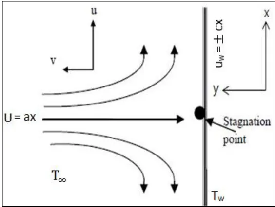
2.2 Stagnation-point flow 16
2.3 Velocity and thermal boundary layer 19
2.4 Sea water constituents 28
2.5 MAPLE 18 window 39
3.1 Research methodology flowchart 42
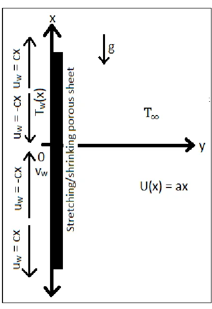
3.2 Stagnation-point flow model over a vertical permeable
surface 44
3.3 Nanoparticle volume fraction effects on velocity profiles
of Cu- fresh water 60
3.4 Nanoparticle volume fraction effects on velocity profiles
of Cu- fresh water (MAPLE software) 60
4.1 Thermal conductivity (κ) of (Cu, Al2O3 and TiO2–fresh
water) nanofluids for different nanoparticle volume
fraction 64
4.2 Thermal conductivity (κ) of (Cu, Al2O3 and TiO2–sea
water) nanofluids for different nanoparticle volume
fraction 64
4.3 Flow configuration (Similarity variables) 65
4.4 Magnetic field effects on velocity profiles of (Cu, Al2O3
and TiO2–fresh water) nanofluids (Injection) 67
4.5 Magnetic field effects on velocity profiles of (Cu, Al2O3
and TiO2–fresh water) nanofluids (Suction) 67
4.6 Magnetic field effects on temperature profiles of (Cu,
Al2O3 and TiO2–water) nanofluids (Injection) 69
4.7 Magnetic field effects on temperature profiles of (Cu,
Al2O3 and TiO2–fresh water) nanofluids (Suction) 69
4.8 Heat source effects on temperature profiles of (Cu, Al2O3
xv 4.9 Heat source effects on temperature profiles of (Cu, Al2O3
and TiO2–fresh water) nanofluids (Suction) 71
4.10 Eckert number effects on temperature profiles of (Cu,
Al2O3 and TiO2–fresh water) nanofluids (Injection) 72
4.11 Eckert number effects on temperature profiles of (Cu,
Al2O3 and TiO2–fresh water) nanofluids (Suction) 72
4.12 Thermal radiation effects on temperature profiles of (Cu,
Al2O3 and TiO2–fresh water) nanofluids (Injection) 73
4.13 Thermal radiation effects on temperature profiles of (Cu,
Al2O3 and TiO2–fresh water) nanofluids (Suction) 74
4.14 Heat sink effects on temperature profiles of (Cu, Al2O3
and TiO2–fresh water) nanofluids (Injection) 75
4.15 Heat sink effects on temperature profiles of (Cu, Al2O3
and TiO2–fresh water) nanofluids (Suction) 76
4.16 Magnetic field effects on velocity profiles of fresh water
(Suction) 78
4.17 Magnetic field effects on velocity profiles of Cu-fresh
water (Suction) 78
4.18 Magnetic field effects on temperature profiles of fresh
water (Suction) 79
4.19 Magnetic field effects on temperature profiles of Cu-fresh
water (Suction) 80
4.20 Nanoparticle volume fraction effects on temperature
profiles of fresh water (Suction) 81
4.21 Nanoparticle volume fraction effects on temperature
profiles of Cu- fresh water (Suction) 81
4.22 Thermal radiation effects on temperature profiles of
Cu-fresh water without magnetic field (Suction) 82
4.23 Thermal radiation effects on temperature profiles of
Cu-fresh water with magnetic field (Suction) 83
4.24 Suction parameter effects on temperature profiles of fresh
water 84
4.25 Suction parameter effects on temperature profiles of
xvi 4.26 Heat source effects on temperature profiles of fresh water
(Suction) 85
4.27 Heat source effects on temperature profiles of Cu-fresh
water (Suction) 86
4.28 Magnetic field effects on velocity profiles of Cu-fresh
water (Injection) 88
4.29 Magnetic field effects on temperature profiles of Cu-fresh
water (Injection) 88
4.30 Grashof number effects on velocity profiles of Cu-fresh
water (Injection) 89
4.31 Grashof number effects on temperature profiles of
Cu-fresh water (Injection) 90
4.32 Heat sink effects on velocity profiles of Cu-fresh water
(Injection) 91
4.33 Heat sink effects on temperature profiles of Cu-fresh water
(Injection) 91
4.34 Heat source effects on velocity profiles of Cu-fresh water
(Injection) 92
4.35 Heat source effects on temperature profiles of Cu-fresh
water (Injection) 93
4.36 Nanoparticle volume fraction effects on velocity profiles
of Cu- fresh water (Injection) 94
4.37 Nanoparticle volume fraction effects on temperature
profiles of Cu- fresh water (Injection) 94
4.38 Thermal radiation effects on velocity profiles of Cu-fresh
water (Injection) 95
4.39 Thermal radiation effects on temperature profiles of
Cu-fresh water (Injection) 96
4.40 Porous parameter effects on velocity profiles of Cu-fresh
water (Injection) 97
4.41 Porous parameter effects on temperature profiles of
Cu-fresh water (Injection) 97
4.42 Injection parameter effects on velocity profiles of Cu-fresh
xvii 4.43 Injection parameter effects on temperature profiles of
Cu-fresh water 99
4.44 Magnetic effects on velocity profiles over Cu-sea water in
the presence of suction 101
4.45 Magnetic effects on velocity profiles over Cu-fresh water
in the presence of suction 101
4.46 Magnetic effects on velocity profiles over Cu-sea water in
the presence of injection 102
4.47 Magnetic effects on velocity profiles over Cu-fresh water
in the presence of injection 102
4.48 Heat source on velocity profiles over Cu-sea water in the
presence of suction 103
4.49 Heat source on velocity profiles over Cu-fresh water in the
presence of suction 104
4.50 Heat source on velocity profiles over Cu-sea water in the
presence of injection 104
4.51 Heat source on velocity profiles over Cu-fresh water in the
presence of injection 105
4.52 Heat source on temperature profiles over Cu-sea water in
the presence of suction 106
4.53 Heat source on temperature profiles over Cu-fresh water in
the presence of suction 106
4.54 Heat source on temperature profiles over Cu-sea water in
the presence of injection 107
4.55 Heat source on temperature profiles over Cu-fresh water in
the presence of injection 107
4.56 Thermal radiation on temperature profiles over Cu-sea
water in the presence of suction 108
4.57 Thermal radiation on temperature profiles over Cu-fresh
water in the presence of suction 109
4.58 Thermal radiation on temperature profiles over Cu-sea
water in the presence of injection 109
4.59 Thermal radiation on temperature profiles over Cu-fresh
xviii 4.60 Grashof number on velocity profiles over Cu-sea water in
the presence of suction 111
4.61 Grashof number on velocity profiles over Cu-fresh water
in the presence of suction 111
4.62 Grashof number on velocity profiles over Cu-sea water in
the presence of injection 112
4.63 Grashof number on velocity profiles over Cu-fresh water
in the presence of injection 112
4.64 Grashof number on temperature profiles over Cu-sea
water in the presence of suction 113
4.65 Grashof number on temperature profiles over Cu-fresh
water in the presence of suction 114
4.66 Grashof number on temperature profiles over Cu-sea
water in the presence of injection 114
4.67 Grashof number on temperature profiles over Cu-fresh
water in the presence of injection 115
4.68 Eckert number on temperature profiles over Cu-sea water
in the presence of suction 116
4.69 Eckert number on temperature profiles over Cu-fresh
water in the presence of suction 117
4.70 Eckert number on temperature profiles over Cu-sea water
in the presence of injection 117
4.71 Eckert number on temperature profiles over Cu-fresh
xix
LIST OF ABBREVIATIONS
a Acceleration, constant (+ve)
A Area
Al2O3 Alumina nanoparticle
b Constants (+ve)
B0 Magnetic field strength
c Constants (+ve)
Cp Specific heat at constant pressure
(Cp)
s Specify heat of solid (Cp)f Specific heat of fluid (Cp)
nf Specific heat of nanofluids
Cu Copper nanoparticle
CuO Copper oxide nanoparticle
DI Deionized water
Ec Eckert number
F Force
𝑓′(η) Dimensionless velocity
𝑓′′(η) Dimensionless skin friction
𝐺𝑟𝑥 local Grashof number
g Gravitational force
h Enthalpy
hx Local heat transfer coefficient (Wm-2K-1)
K Porous parameter
KCl Potassium chloride
K1 Permeability of the porous medium (m2)
xx
L Length
m Mass
M Magnetic strength parameter (Nm Ω-1A-2 s-1)
MHD Magnetohydrodynamics
N Thermal radiation parameter (s3m-2)
Nu Nusselt number
Nux Local Nusselt number
ODE Ordinary differential equations
Pr Prandtl number
Prfw Prandtl number for fresh water
Prsw Prandtl number for sea water
Q Heat transfer rate
Qo Dimensional heat generation/absorption coefficient (kgm-1s-3K-1)
qr Thermal radiative heat flux (Wm-2)
Rex Local Reynolds number
RK4 Runge-Kutta method
RKF45 Runge-Kutta-Felhberg method
S Suction/injection parameter (kgs-1m-3)
T Fluid temperature in Cartesians co-ordinates (x,y)
TiO2 Titanium dioxide nanoparticle
u Velocity component in x-direction
uw Stretching/shrinking surface velocity
uT Tangential velocity
U Free stream velocity in Cartesians co-ordinates (x,y)
UT Tangential boundary velocity
v Velocity component in y-direction
x Direction along the plate
y Direction perpendicular to the plate
2-D Two-dimensional
3-D Three-dimensional
xxi Greek symbols
α Thermal diffusivity
αnf Thermal diffusivity of the nanofluid
αf Fluid thermal diffusivity
β Thermal expansion coefficient
γ Buoyancy parameter
δ Boundary layer thickness
δV(x) Velocity boundary layer thickness in x-direction
δT (x) Thermal boundary layer thickness in x-direction
η Similarity variable
θ(η) Dimensionless temperature of the fluid
θw Wall temperature excess ratio parameter
θ′(η) Dimensionless heat transfer rate
κ Thermal conductivity
κeff Effective thermal conductivity
κf Thermal conductivity of the fluid
κnf Thermal conductivity of the nanofluid
κs Thermal conductivity of solid
λ Heat generation/absorption parameter
λI Heat generation/absorption parameter for injection
λS Heat generation/absorption parameter for suction
μ Dynamic viscosity
𝑣 Kinematic viscosity
𝑣𝑤 Wall mass flux
ρ Density
ρf Density of fluid
ρnf Effective density of the nanofluid
ρs Density of solid
(ρCp)f Heat capacitance of fluid (ρCp)nf Heat capacitance of nanofluid
(ρCp)s Heat capacitance of solid
xxii
σ* Stefan–Boltzmann constant
τ Shear stress
ϕ Nanoparticles volume fraction
ψ Stream function
Superscripts
′ Differentiate with respect to y, x, η correspondingly
Subscripts
f Fluid
fw Fresh water
I Injection
nf Nanofluid
s Solid
S Suction
sw Sea water
T Tangential
w Wall
xxiii
LIST OF APPENDICES
APPENDIX TITLE PAGE
A PROGRAM FOR STAGNATION-POINT FLOW 132
B PROGRAM FOR ISOTHERMAL CASE 146
xxiv
LIST OF PUBLICATIONS
Journal Articles
1. Impact of heat transfer on MHD boundary layer of copper nanofluid at a stagnation point flow past a porous stretching and shrinking surface with variable stream conditions
Ashwin Kumar, Norasikin Binti Mat Isa, Kandasamy
ARPN Journal of Science and Technology, 5(5), (2015), 219-231.
In Press
2. Impact of injection on a stagnation–point flow of copper nanofluids over a vertical porous shrinking or stretching plate in the presence of magnetic field Ashwin Kumar, Norasikin Binti Mat Isa, Vibhu Vignesh, Kandasamy
ARPN Journal of Engineering and Applied Sciences (Scopus Indexed)
3. Heat transfer characteristic of nanofluids on MHD stagnation–point flow towards stretching or shrinking plate in the presence of injection or suction
Ashwin Kumar, Norasikin Binti Mat Isa, Vibhu Vignesh, Kandasamy ARPN Journal of Engineering and Applied Sciences (Scopus Indexed)
4. Effect of injection on thermal and flow characteristics of copper MHD nanofluid in the presence of sea water/fresh water
Ashwin Kumar, Norasikin Binti Mat Isa, Vibhu Vignesh, Kandasamy ARPN Journal of Engineering and Applied Sciences (Scopus Indexed)
5. Impact of suction on a stagnation–point flow of copper nanofluids over a vertical porous plate in the presence of magnetic field
CHAPTER 1
INTRODUCTION
1.1 Background
Heat transfer is one of the most important processes in many industrial and consumer products. The inherently poor thermal conductivity of conventional fluids puts a fundamental limit on heat transfer. Therefore, for more than a century since Maxwell in 1904, scientists and engineers have made great efforts to break this fundamental limit by dispersing millimeter- or micrometer-sized particles in liquids. However, the major problem with the use of such large particles is the rapid settling of these particles in fluids, clogging and erosion of pipes and channels. As extended surface technology has already been adapted to its limits in the designs of thermal management systems, technologies with the potential to improve a fluid’s thermal properties are of great interest once again. The concept and emergence of nanofluids is related directly to the trend in miniaturization and nanotechnology. Maxwell’s concept is old, but what is new and innovative in the concept of nanofluids is the idea that particle size is of primary importance in developing stable and highly conductive nanofluids.
Ultrahigh-performance cooling is one of the most vital needs of many industrial technologies. However, inherently low thermal conductivity is a primary limitation in developing energy efficient heat transfer fluids that are required for
ultrahigh-performance cooling. Nanofluids are engineered by suspending
2 term coined by Choi (1995) to describe this new class of nanotechnology-based heat transfer fluids that exhibit thermal properties superior to those of their host fluids or
conventional particle fluid suspensions. Nanofluid technology, a new
interdisciplinary field of great importance where nanoscience, nanotechnology, and thermal engineering meet, has developed largely over the past decades. The goal of nanofluids is to achieve the highest possible thermal properties at the smallest possible concentrations (preferably < 1% by volume) by uniform dispersion.
Based on the above discussion of the versatile properties and applications of nanofluids, the research study has been narrowed and had made an approach to synthesize Al2O3, Cu and TiO2 based nanofluids which can transfer heat more
effectively. Fresh water and sea water are chosen as base fluids. The enhancement of heating or cooling in an industrial process may promote conservation of energy, reduce process time, raise thermal rating and lengthen the working life of equipment. A number of studies have been conducted to gain an understanding of the heat transfer performance for their practical application to heat transfer enhancement. Thus the advent of high heat flow processes has created significant demand for new technologies to enhance heat transfer.
There are several methods to improve the heat transfer efficiency. Some methods are utilization of extended surfaces, application of vibration to the heat transfer surfaces, and usage of micro channels. Heat transfer efficiency can also be improved by increasing the thermal conductivity of the working fluid. Commonly used heat transfer fluids such as water, ethylene glycol, and engine oil have relatively low thermal conductivity, as compared to the thermal conductivity of solids. High thermal conductivity of solids can be used to increase the thermal conductivity of a fluid by adding nanoparticles to that fluid. However, the emergence of modern materials technology provide the opportunity to produce nanometer-sized particles which are quite different from the parent material in mechanical, thermal, electrical, and optical properties.
1.2 Problem statement
3 environmental and industrial applications is to find the flow and heat transfer behaviors of nanofluids towards the stretching/shrinking surface on various stream conditions when injection/suction is present. This will help in understanding the heat transfer processes of the surfacing materials, hence improving the quality of the final products.
1.3 Aim of Study
The aim of the study is to obtain a mathematical derivation suitable to the stagnation-point flow and study the behaviors of four different nanofluids. The lack of knowledge on the behavior of nanofluids on stagnation-point flow over a stretching/shrinking permeable surface prevents the nanofluids from the widespread use in industrial applications.
1.4 Objectives of the study
The main theme of this study is to modify a mathematical equation for the stagnation-point flow of nanofluids. Based on the research gaps identified in literature review, this study has been done according to the following objectives:
1. To derive a mathematical equation for studying mechanical and thermal behavior of nanofluids in stagnation-point flow in the influence of mechanical field strength and Grashof number and various other parameters i.e. thermal radiation, heat sink/source, suction/injection parameter, Eckert number, Nusselt number, nanoparticle volume fraction and porous parameter. 2. Study the heat transfer rate, thermal and velocity distribution of Al2O3, Cu
and TiO2 nanoparticles in fresh water to predict the best and appropriate
nanofluid for stagnation-point flow and comparing the results by changing the base fluid to sea water for various stream conditions.
1.5 Scope of study
4 permeable shrinking/stretching surface under prescribed parameters effect. The surface of the wall is permeable in order to allow suction or injection. Some prescribed parameters, such as porous medium, heat radiation, variable viscosity and suction/injection parameter, are included in the study on the boundary layer behaviors. The governing partial differential equations are approximated by natural convective flow model, MHD flow model, laminar, stagnation-point flow model. Due to the use of a porous medium, it takes into account the effect of inertia on solid boundary and is simplified using boundary layer theory and Boussinesq approximations.
The partial differential equations governing the problem under consideration are transformed by similarity transformation into a system of ordinary differential equations with boundary conditions. The numerical scheme, Runge-Kutta-Fehlberg in conjunction with shooting method is used to find the dimensionless velocity and temperature profiles. Alumina, Copper and Titanium dioxide as nanoparticles, fresh water and sea water as base fluids are taken into consideration for studying the behaviour of nanofluids in laminar stagnation-point flow over porous surface. MAPLE 18 software is used to solve boundary layer equations, which uses Runge-Kutta-Fehlberg method for solving ordinary differential equations.
1.6 Contributions towards nanofluid field
The proposed mathematical equation for nanofluids in stagnation-point flow over a shrinking/stretching surface would provide better understanding in mechanical and also thermal behaviors of the nanofluids. The major contributions are:
1. A new mathematical derivation with magnetic field strength, Nusselt number and Grashof number helps to get better understanding of the mechanical and thermal behavior of nanofluids flowing horizontally under various governing parameters.
5 1.7 Research motivation
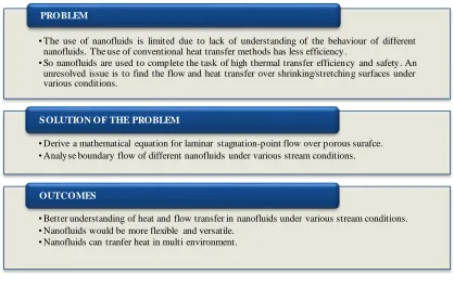
The study focuses on new mathematical equation for stagnation-point flow and boundary layer flow of nanofluids over a vertical permeable membrane under the influence of magnetic field strength. The study motivation chart is shown in Figure 1.1 that highlights the problem, its solution and outcomes.
Figure 1.1 Research motivation
1.8 Thesis layout
This thesis is organized as follows:
In Chapter 1, the introduction, the very beginning of all the research works that has been done for the past year. The problems that are to be dealt with at the end of this research are listed in the problem statement. The aim and the objectives that have pushed this research work with numerous findings and data are provided consecutively. The contribution to the field of nanofluids by this research work are stated after that.
• The use of nanofluids is limited due to lack of understanding of the behaviour of different nanofluids. The use of conventional heat transfer methods has less efficiency.
• So nanofluids are used to complete the task of high thermal transfer efficiency and safety. An unresolved issue is to find the flow and heat transfer over shrinking/stretching surfaces under various conditions.
PROBLEM
• Derive a mathematical equation for laminar stagnation-point flow over porous surafce. • Analyse boundary flow of different nanofluids under various stream conditions.
S OLUTION OF THE PROBLEM
• Better understanding of heat and flow transfer in nanofluids under various stream conditions. • Nanofluids would be more flexible and versatile.
• Nanofluids can tranfer heat in multi environment.
[image:32.596.115.533.221.498.2]6 In Chapter 2, a collection of studies of existing works in several key areas of nanofluids research and background to the field of nanofluids along with examples of existing types of nanofluids are discussed. It also highlights the existing issues related to heat transfer, high pumping power problems. The data from the numerous existing researches from all over the world which are used for the research work purpose are provided in this chapter.
In Chapter 3, the way this project is carried out is explained. Mathematical modelling by which the general fluid dynamics equation suitable for incompressible flow is transformed into an equation suitable for stagnation-point flow is elaborated. The physical flow model is presented and discussed. The MAPLE software using which the governing equations is executed, is explained in this chapter. A unique program coding suitable for solving ODE is written exclusively for this situation. For validation of MAPLE software, data are analyzed with the previous presented results.
In Chapter 4, values and graphs obtained from the numerical calculation are presented and discussed briefly. At first the study of behavior of three nanofluids taking fresh water as base fluid. Then Cu-fresh water nanofluid extensive study of behavior in the presence of suction and injection for various governing parameters are discussed. At last, the behavior of Cu-sea water nanofluid in the presence of suction and injection is discussed and compared with the behavior of Cu-fresh water.
CHAPTER 2
LITERATURE REVIEW
Numerous researches on nanofluids have been carried out in the past two decades, the implementation of nano-meter sized particle to the heat transfer fluids to enhance their heat transfer rate. Nano fluids have been used for engine cooling, engine transmission oil, boiler exhaust flue gas recovery, cooling of electronic circuit, especially in nuclear cooling system, solar water heating, defense and space application and biomedical application, etc. To increase the thermal conductivity of base fluids, many factors have to be considered, such as the shape and size of nanoparticle, thermal conductivity of nanoparticle, concentration of nanoparticle, Prandtl number, and Reynolds number.
2.1 Fluid mechanics
8 On the other hand, the governing equation of fluid dynamics, called the Navier– Stokes equation, would never be described as simple. The common theme is to simplify the mathematical or experimental model used to describe the flow without sacrificing the relevant physical phenomena. The art of fluid mechanics is to know when it is safe to neglect the effects of physical phenomena that are judged to have little impact on the flow. Once it is decided that certain physical phenomena be neglected, the corresponding terms are dropped from the governing equations, thereby decreasing the difficulty in obtaining a solution (Shaughnessy et al., 2005).
One of the intentions of this study is to integrate these modern computational aids into a first course in fluid mechanics. The use of symbolic mathematics codes, such as MATHCAD, MAPLE, Mathematica, and others like them, helps in learning fluid mechanics, to simplify calculations and to visualize the mathematics.
2.2 Fluid dynamics
There are three fundamental physical principles upon which all of fluid dynamics is based on (Anderson, 2012):
1. Mass is conserved.
2. Newton’s second law, F= ma 3. Energy is conserved.
9 2.2.1 Governing equations
In the current study, Navier-Stokes governing equations are used. The advantage of using a time-independent Navier-Stokes approach for incompressible flow is its inherent ability to evolve to the correct steady-state solution (Anderson, 2012). The steady, 2-D stagnation-point flow of a viscous and incompressible fluid over a
stretching/shrinking vertical porous surface is placed in the plane y = 0 of a Cartesian
system of coordinates with the x-axis along the sheet as shown in Figure 2.1. Figure 2.1 shows the flow configuration with conventional variables. The flow being confined to y > 0 that is fluid occupies the half plane (y > 0). It is assumed that the velocity 𝑢𝑤(𝑥) and the temperature 𝑇𝑤(𝑥) of the stretching/shrinking sheet is
proportional to the distance x from the stagnation-point, where 𝑇𝑤(𝑥) < 𝑇∞. g is the
gravity acceleration.
Figure 2.1 Flow configuration
Under these assumptions along with the Boussinesq and boundary layer
[image:36.596.212.426.359.671.2]10
through a porous medium (highly permeable) over a heated porous
stretching/shrinking surface (with the application of Darcy's law) are, in the usual notations,
1. Continuity equation
Physical principal: Mass is conserved
𝜕𝑢 𝜕𝑥 +
𝜕𝑣
𝜕𝑦= 0 (2.1)
2. Momentum equation Physical principle: F = ma
𝑢𝜕𝑢 𝜕𝑥+ 𝑣
𝜕𝑢
𝜕𝑦= 𝑈(𝑥) 𝑑𝑈(𝑥)
𝑑𝑥 + 𝜇𝑛𝑓 𝜌𝑛𝑓
𝜕2𝑢 𝜕𝑦2+
𝜇𝑛𝑓
𝜌𝑛𝑓𝐾(𝑈(𝑥) − 𝑢) (2.2)
In equation 2.2, 𝑈(𝑥) stands for the stagnation-point velocity in the inviscid free stream, 𝑢 and 𝑣 are the components of velocity respectively in the x and y directions, 𝐾 is the permeability of the porous medium, 𝜇𝑛𝑓 is the dynamic viscosity of nanofluids, 𝜌𝑛𝑓is the nanofluids’ density.
By using the boundary layer approximations, the boundary layer equation of energy for fluid temperature T in the presence of heat source/heat sink, thermal radiation and viscous dissipation is
3. Energy equation
Physical principle: Energy is conserved
𝑢𝜕𝑇 𝜕𝑥 + 𝑣
𝜕𝑇 𝜕𝑦 = 𝛼𝑛𝑓
𝑑2𝑇 𝑑𝑦2+
𝑄0 (𝜌𝐶𝑝)
𝑛𝑓
(𝑇 − 𝑇∞) − 1 (𝜌𝐶𝑝)
𝑛𝑓 𝜕𝑞𝑟
𝜕𝑦 +
𝜇𝑛𝑓 (𝜌𝐶𝑝)
𝑛𝑓
(𝜕𝑢 𝜕𝑦)
2
(2.3)
𝐶𝑝 is the specific heat at constant pressure of nanofluids, α is the thermal diffusivity coeficient of fluids, 𝑄0 is the dimensional heat generation/absorption coefficient of fluids and 𝑞𝑟 is the radiative heat flux respectively. The equation 2.1 to equation 2.3 are subjected to the boundary conditions (for shrinking or stretching plate):
𝑣 = 𝑣𝑤, 𝑢 = 𝑢𝑤(𝑥) = ±𝑐𝑥, 𝑇 = 𝑇𝑤(𝑥) 𝑎𝑡 𝑦 = 0
11 where a and c are positive constants. 𝑣𝑤 is the wall mass flux. 𝑇𝑤(𝑥) and 𝑇∞ are also constants with 𝑇∞ > 𝑇𝑤(𝑥).
2.2.2 Similarity Solutions
The similarity solutions for equation 2.1 to equation 2.3 with boundary condtions are in the following form:
1. Stream functions
Stream function is defined for incompressible flow in 2-D with axisymentry. It can be used to plot streamlines , which represent the trajectories of particles in steady flow. Stream functions will exclude pressure. Usefulness of stream functions is that the velocity components in (x,y) direction at any given point are given by partial derivatives of stream function at that point.
Stream function, ψ = √𝑐 ∙ 𝜈𝑓∙ 𝑓(η) ∙ 𝑥
2. Similarity variable (dimensionless distance), η = √𝐶
𝜈𝑓∙ y
3. Dimensionless temperature, 𝜃(η) = 𝑇 −𝑇∞
𝑇𝑤−𝑇∞
2.3 Heat transfer
Heat transfer and temperature distribution are of great importance to engineers because of its almost universal occurrence in many branches of science and engineering. Heat transfer is thermal energy transfer in transit due to a spatial temperature difference (Bergman, 2011). Fluid dynamics is closely associated with heat transfer. In a system, heat flow occurs wherever temperature gradient is present. Thus the knowledge of temperature distribution is essential in heat transfer studies. The energy transfer of heat takes place by three distinct modes (Sachdeva, 2010):
1. Conduction – Exists in a system, comprising molecules of a solid, liquid or gas.
2. Convection – Exists between fluid and solid.
12 2.3.1 Convection
Convective heat transfer is one of the distinct modes of heat transfer for transferring heat between a solid surface and the fluid moving on it. Convection is only possible in the presence of a fluid medium. Transfer of energy in convection is mostly due to the bulk motion of fluid particles. This kind of heat transfer is present mostly in liquids and gases. Heat transfer by convection is always accompanied by conduction, because the transfer of energy between the solid surface and the fluid at the surface can take place only by conduction (Sachdeva, 2010).
2.3.1.1 Convection in nanofluids
The study on the heat transfer convection is very limited as compared to the experimental and theoretical study of the thermal conductivity of nanofluids. It is very important to know that enhancement in thermal conductivity of nanofluid does not necessarily increase the heat transfer capability of it. The physical properties of nanofluids compared to pure fluids such as viscosity, heat capacity, density and stability of nanoparticles in the fluid may deteriorate. Natural convection, force convection and mixed convection can be obtained in nanofluids. Natural convection is the type of convection which the flow is generated by buoyancy force during cooling or heating of the fluid. Force convection is the convection in which the flow is due to external forces such as a pump, fan, compressor and etc. The law of convection is Fourier’s conduction law (Bergman, 2011):
𝑄 = ℎ𝐴(𝑇𝑤− 𝑇𝑓) (2.5)
where Q is the amount of heat transfer between the wall and the fluid in motion, A is the solid-liquid interface area, Tw is the wall temperature, and Tf is the
13 a certain volume fraction of each phase which is named as mixture model. In nanofluids, due to the small particles being suspended in an ordinary fluid and their higher stability, the single phase model is more applicable.
2.3.1.2 Convective boundary layer flow over a porous surfaces
Single phase model has been used in several studies of convective heat transfer with nanofluids, (Khanafer et al., 2003; Maiga et al., 2004; Koo & Kleinstreuer, 2005). Convective flow, heat transfer in porous surface, has been a topic of interest for researchers, as it plays a crucial role in diverse applications, such as thermal insulation, extraction of crude oil and chemical catalytic reactors etc. Numerous authors proposed models and group theory methods to study convective boundary layer flow of fluids, which are (Birkhoff, 1948, 1960; Yurusoy et al., 2001). Pak & Cho (1998) analyzed the heat transfer by convection in Al2O3-water and TiO2-water
nanofluids. The flow of nanofluid is turbulent, and observes that increase in nanoparticle volume fraction and the Reynolds number, increases the Nusselt number of the nanofluids. However, in a nanofluid having 3% volume of nanoparticle, the convective heat transfer coefficient for an average fluid velocity was 12% lower than that of pure water. The result appears to disagree with the observation of (Lee & Choi, 1996). Lee & Choi (1996) investigated convective heat transfer in microchannel using an unspecified nanofluid. Laminar flow was selected as the flow of nanofluids and found a reduction in thermal resistance by a factor of 2. Heat power dissipation by nanofluids were measured to three times more than pure water.
14 convection heat transfer coefficient must meet for a similarity type solution to exist. Bachok et al. (2010) have studied theoretically the problem of steady boundary-layer flow of a nanofluid past semi-infinite flat plate in uniform free stream and it is found that dual solutions exist when the plate and the free stream flow move in opposite directions. The problems of laminar fluid flow resulting from the stretching of a flat plate in a nanofluid have been investigated by (Khan & Pop, 2010). Kuznetsov & Neild (2011) studied the double-diffusive natural convective boundary-layer flow of a binary nanofluid past a vertical plate incorporated it with the effects of Brownian motion and thermophoresis.
2.3.2 Important points about the heat transfer of nanofluids
It should be noted that the most important reason of using nanofluids is to improve the heat transfer of fluids. The experience in this field has showed that other properties besides the thermal conductivity, such as the Cp, α, heat fusion and etc. of the nanoparticle have great impact on nanofluids. This point has not been mentioned elsewhere. Most of the researchers have mainly focused on the thermal conductivity of nanofluids without considering these properties. This is the main key in making useful nanofluids for practical applications. Some other key points for nanofluids are (Kahar, 2014):
1. The thermal conductivity enhancement ratio increases with increasing
particle volume fraction.
2. The sensitivity to volume fraction depends on particle material and base fluid (the sensitivity is higher for particle material with higher thermal conductivity and base fluid with lower thermal conductivity).
3. The thermal conductivity of nanofluids shows higher sensitivity to
temperature than that of the base fluid, consequently the thermal conductivity enhancement ratio also shows high sensitivity to temperature.
15 6. For the suspensions containing the same base liquid and nanoparticles, the thermal conductivity enhancements were highly dependent on the specific surface area of the nanoparticles.
7. For the suspensions using the same nanoparticles, the enhanced thermal conductivity ratio decreased with increasing thermal conductivity of the base fluid.
2.4 Classification of flow
Flow is generally classified into uniform and non-uniform flow, compressible and incompressible flow, steady and unsteady flow, and laminar and turbulent flow. A steady flow is one in which the conditions (velocity, pressure and cross-section) may differ from point to point but do not change with time (Shaughnessy et al., 2005). If at any point in the fluid, the conditions change with time, the flow is described as unsteady. Density of all fluids will change if pressure changes. Liquids are quite difficult to compress, so under most steady conditions they are treated as incompressible. In some unsteady conditions very high pressure differences can occur and it is necessary to take these into account.
2.4.1 Stagnation-point flow
16 electronic devices by fans, cooling of nuclear reactors, and many other hydrodynamics processes.
Figure 2.2 Stagnation-point flow (ABD-Elaziz & Ahmed, 2008)
Consider the development of the 2-D boundary layer flow of a micro polar fluid near the rear stagnation point of a vertical plane surface in a porous medium. For analysis, rectangular Cartesian coordinates (x,y) are used in which x and y are taken as the coordinates along the wall and normal to it, respectively. u and v are the components of fluid velocity in the x and y directions, respectively. The flow configuration is shown schematically in Figure 2.1.
[image:43.596.177.459.133.346.2]17 Mahapatra & Gupta (2002) studied the behavior of flow and heat transfer over stretching plate using two-dimensional boundary layer flow, stagnation-point flow and heat transfer. The results showed that when stretching surface velocity is lower than the free stream velocity, boundary layer is formed. When the stretching surface velocity is higher than the free steam velocity, an inverted boundary layer is formed. Magentohydrodynamics stagnation-point flow and boundary layer flow is studied by (Mahapatra & Gupta, 2001; Ishak et al., 2009) over a stretching surface. According to their results, it is clear that when stretching velocity is lower than that of free stream velocity, there is an increase in velocity at one point with an increase in magnetic field. Pal et al. (2014) analyzed the behavior of Cu, Al2O3 and TiO2
nanoparticles taking fresh water as base fluid at a stagnation point flow on shrinking or stretching surface with thermal radiation. Pal et al. (2014) took the Prandtl number for water as 6.8. He studied the behavior of temperature, velocity profiles, skin friction and heat transfer rate and found that temperature profiles are high in the case of shrinking surfaces.
2.5 Flat plate boundary-layer concept
18 2.5.1 Velocity boundary layer
Consider the flow over a flat plate, the velocity here in front of the leading edge of the plate is uniform. Due to the no slip condition to be satisfied at the surface of the plate, the velocity of the fluid is reduced to zero relative to the surface. This results in the retardation of the fluid particles in the adjoining fluid layers until at a distance y = δ from the surface (called boundary layer thickness) this effect becomes negligible. The deceleration of the fluid particles in the boundary layer is associated with shear stress, τ. The effect of shear (viscous) forces originating at the surface extends into the body of the fluid, but with increasing distance, y, from the surface, the x velocity component of the fluid, u, increases until it approaches the free stream velocity, U∞
(Kahar, 2014). δV(x) is the velocity boundary layer thickness in x-direction. The
velocity and thermal boundary layer thickness is shown in Figure 2.2. The free stream velocity (U∞) is zero in Figure 2.2.
It is most essential to distinguish between laminar and turbulent boundary layers. Initially, the boundary layer development is laminar for the flow over a flat plate. Depending upon the flow field and fluid properties, at some critical distance from the leading edge small disturbances in the flow begin to get amplified, a transition process takes place and the flow becomes turbulent. In laminar boundary layer, the fluid motion is highly ordered whereas the motion in the turbulent boundary layer is highly irregular with the fluid moving to and from all directions. Due to fluid mixing resulting from these macroscopic motions, the turbulent boundary layer is thicker and the velocity profile in turbulent boundary layer is flatter than that in laminar flow.
2.5.2 Thermal boundary layer
A thermal boundary layer will develop if the surface temperature and free stream temperature are different. In Figure 2.2, at the leading edge, the temperature profile is uniform with T = T∞. The wall is maintained at Tw. δT (x) is the thermal boundary
19 approaches the free stream temperature. The effects of heat transfer penetrate further into free stream resulting in the growth of thermal boundary layer thickness. Like the velocity boundary, the thermal boundary will also be defined as laminar or turbulent depending upon the critical value of Reynolds number (Kahar, 2014).
Figure 2.3 Velocity and thermal boundary layer (Kandasamy et al., 2011)
2.5.3 No slip boundary conditions
[image:46.596.207.432.175.400.2]20 2.6 Porous surface
Porous surface consists of void spaces called pores distributed throughout solid matrix. Porous material are permeable to a variety of fluids that is fluids should be able to penetrate through one face of septum made of the material and emerge on the other side. They can be used as an insulator (for all temperature ranges) and can be used as a heat transfer promoter for either sensible or latent heat transfer. Porous medium is characterized by a very large surface area to a volume ratio. This peculiar feature of the porous media can be utilized to either distribute heat energy uniformly or to enhance the heat transfer in heat exchange systems. The fluid storage capacity of porous media, such as paper, is mainly determined by its porosity. Porosity is the geometrical property of porous medium. The absorption and spreading rate is determined by permeability. Permeability is the measure of ability of a porous media to transmit fluids. The unit of measurement is Darcy, named after a French scientist Darcy in 1856. Permeability is the most important physical property of a porous media. Different transport models are available in the literature, are used to model energy and momentum transport in porous media. These models are based upon governing equations which are inherited from the corresponding free-fluid flow.
Porous materials are encountered literally everywhere in everyday life, in technology and in nature. There is a large variety of natural and artificial porous materials encountered in practice, such as: soil, sandstone, limestone, ceramics, foam, rubber, bread, lungs, and kidneys. With the exception of metals, some dense rocks, and some plastics, virtually all solids and semi-solid materials are porous to varying degrees. Aquifers (from where water is pumped), sand filters (for purifying water), reservoirs (which yield oil or gas), packed and fluidized beds in the chemical engineering and the root zone in agricultural industry may serve as additional examples of porous media domains.
2.6.1 Momentum transport in porous surface
21 models before considering any model describing the temperature distribution. The first momentum equation which describes the transport phenomenon of the fluid flow through porous media were deduced experimentally by Darcy in 1856. Since then several flow models which are based on phenomenological observations rather than analytical approaches have been developed to match the same purpose.
2.6.2 Energy transport in porous surface
The knowledge of the heat transfer characteristics in porous media is of great importance in many applications. For example, in chemical reactor design it is important to know the thermal transport characteristics of the porous media in order to make accurate predictions of the variation in reaction rate caused by the inlet temperature disturbances. Temperature histories are also important for the design of packed bed thermal storage system. Therefore, it is desirable to have the proper values of the heat transfer coefficient and effective thermal conductivity, so that the time required to heat up the solid particles can be estimated (Grangeot et al., 1984).
2.7 Magnetohydrodynamic (MHD)
The field MHD was initiated by Hannes Alfven in 1942, an astrophysicist. Magneto-hydrodynamics is the branch of continuum mechanics which deals with the flow of
electrically conducting fluids in electric and magnetic fields. The word
22 2.7.1 Steady MHD flow over porous surfaces
Chamkla & Aly (2010) have analyzed MHD free convection flow of a nanofluid past a vertical plate in the presence of heat generation or absorption effects. Singh (2001) analyzed the MHD free convection and mass transfer flow with the heat source and thermal diffusion. The paper deals with the study of free convection and mass transfer flow of an incompressible, viscous and electrically conducting fluid past a continuously moving infinite vertical plate in the presence of large suction and under the influence of uniform magnetic field considering heat source and thermal diffusion. Rajeswari et al., (2009) examined the governing equations for steady incompressible fluid past a semi-infinite vertical porous plate embedded in a porous medium and subjected to the presence of transverse magnetic field. Hamad & Pop (2011) have examined the unsteady MHD free convection flow past a vertical permeable flat plate in a rotating frame of reference with constant heat source in a nanofluid. Makinde (2009) used a shooting numerical technique to analyze MHD boundary-layer flow and mass transfer past a vertical plate in a porous medium with constant heat flux at the plate surface. Except for a few, boundary layer flows have been studied using either a constant surface temperature or a constant heat flux boundary condition.
2.8 Thermal conductivity enhancement in nanofluids
Maxwell in 1904 and Hamilton & Crosser (1962) developed a classical model using the medium theory. This model is experimentally verified by the data for mixtures with lower volume fractions of micrometer and millimeter sized particles. The data obtained from the experiments showed that nanofluids have high thermal conductivity that cannot be predicted accurately by the models suggested by Maxwell in 1904 and (Hamilton & Crosser, 1962). Wang et al. (1999); Keblinski et al. (2002) have suggested few mechanisms that are not considered by classical models. These mechanisms elucidates the enhanced thermal conductivity of nanofluids.
23 the structural effects. Brownian motion, van der Waals force, and electrostatic force significantly causes the microscopic motion of nanoparticles in nanofluids. Keblinski et al. (2002) explained the increase in nanofluids heat transfer must be due to the four possible mechanisms and the mechanisms are:
1. Brownian motion of the nanoparticles,
2. Liquid layering at the liquid/particle interface, 3. Nature of the heat transport in the nanoparticles, 4. The effect of nanoparticle clustering.
From Eastman et al. (1997) report, nanoparticles induced in water, made a promising turning point of using nanofluids in heat transfer devices. The article showed that Copper Oxide (CuO) particles suspended in nanoparticle volume concentration of 0.05 in fresh water, the enhancement in thermal conductivity is almost 60% compared to fresh water. Murshed et al. (2005, 2009) found that
nanofluids prepared by dispersing 5% volume fraction Titanium dioxide
nanoparticles in deionized water, thermal conductivity enhancement is observed through hot wire technique to be nearly 33% and close to 30%, respectively over the base fluid.
A benchmark study on the thermal conductivity of nanofluids was made by (Buongiorno et al., 2009). Variety of experimental approaches, including transient hot wire method, steady-state methods and optical methods are performed and it was found that the thermal conductivity increases with volume concentration and aspect ratio. The resulted thermal conductivities were then validated through effective medium theory developed for dispersed particles.
2.9 Impact and potential benefits of nanofluids
In industries, nanofluids technology is greatly considered, where the heat transfer characteristics of heat exchanger and cooling devise is vital. Choi et al. (2004); Zussman (1997) showed that when the nanoparticles are dispersed in conventional heat transfer fluids, nanofluids can offer variety of benefits. These benefits include (Murshed, 2008):
24 3. Miniaturized systems
4. Pumping power reduction
5. Cost and energy savings
2.9.1 Applications of nanofluids
In the modern era of fast computers and battery operated devices, such as mobile phones and laptops, have accelerated the invention of new coolants and heat transfer fluids. In last two decades researchers have been working to find a new technology to perform this task. Many researches have been conducted over the years to understand the behavior of these fluids. Nanofluids are very important invention of this period which has wide applications, few are listed in Table 2.1.
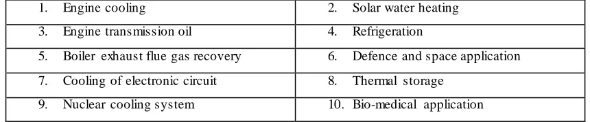
Table 2.1 Applications of nanofluids
1. Engine cooling 2. Solar water heating
3. Engine transmission oil 4. Refrigeration
5. Boiler exhaust flue gas recovery 6. Defence and space application
7. Cooling of electronic circuit 8. Thermal storage
9. Nuclear cooling system 10. Bio-medical application
2.10 Nanoparticles
Nanotechnology is rapidly developing in the recent years. Particles that are in nano-meter size that is less than 100 nanonano-meters normally, instead of micro-nano-meter sized are suspended in conventional heat transfer liquids. Researchers have been working to increase the heat transfer capacity of conventional fluids by introducing different nanoparticles such as metals (Cu, Al, Au), oxides (CuO, Al2O3, TiO2, ZnO), etc. and
[image:51.596.104.534.371.460.2]