© 2017, IRJET | Impact Factor value: 5.181 | ISO 9001:2008 Certified Journal
| Page 384
Development of IOS Application for Design of Flat Slabs
Shreelakshmi MJ
1, Mr. Manjunatha L
2, Miss. Spandana B
3,Ritesh L
41,4
PG Student, Department of Civil Engineering, SJB Institute of Technology, Bengaluru, Karnataka, India
2,3Assistant Professor, Department of Civil Engineering, SJB Institute of Technology, Bengaluru, Karnataka, India
---***---Abstract -
Flat slab structural building provides a benefit over conventional slab structures because of their architectural, functional and economical aspects. Because of the absence of deep beams, flat slab structural system is significantly more flexible for lateral loads. A traditional common practice in construction is to support slab by beam and beam supported by column this may be called as beam slab load transfer construction technique. As due to this old traditional construction net height of room is reduced. Hence to improve aesthetical and structural aspect of multi-storey, shopping mall ,offices, warehouses ,public community hall etc. are constructed in such a way were slab are directly on columns. This types of slab directly supported on column termed as flat slab. The present work is done by developing IOS application because in present day’s use of application is increasing day to day. So keeping in that the development of IOS application is done and the results are compared with the application developed.Key Words: Flat Slabs, Storey Shear, Storey
Displacement, IOS Application, Swift Programming Language.
1. INTRODUCTION
Reinforced concrete Flat slabs are one of the most popular floor systems used in residential buildings, car parks and many other structures. They represent elegant and easy-to-construct floor systems. Flat slabs are favored by both architects and clients because of their aesthetic appeal and economic advantage. A flat slab floor system is often the choice when it comes to heavier loads such as multi-storey car parking, libraries and multi-storey buildings where larger spans are also required.
Flat slab called beamless slab is a slab supported directly by columns without beams. A part of slab bounded on each of the four sides by Centre line of column is called a panel. Panel may be divided into column strip and middle strip. The flat slab is often thickened closed to supporting columns to provide adequate strength in shear and to reduce the amount of negative reinforcement in the support regions. The thickened portion i.e., the projection below the slab is called drop or drop panel. Flat slab systems are popular for use in office and residential buildings, hospitals, schools and hotels.
1.1 Choice of Type of Slab Floor
The choice of type of slab for a particular floor depends on many factors. Economy of construction is obviously an important consideration, but this is a qualitative argument until specific cases are discussed, and is a geographical variable. The design loads, required spans, serviceability requirements, and strength requirements are all important. For beamless slabs, the choice between a flat slab and a flat plate is usually a matter of loading and span. If architectural or other requirements rule out capitals or drop panels, the shear strength can be improved by using metal shear heads or some other form of shear reinforcement, but the costs may be high.
1.2
Advantages of Flat Slab Systems
1. The ease of the construction of formwork 2. The ease of placement of flexural reinforcement.. 3. The ease of casting concrete.
4. The free space for water, air pipes etc. between slab and a possible furred Ceiling.
5. The free placing of walls in ground plan.
6. The use of cost effective pre stressing methods for long spans in order to reduce Slab thickness and deflections as also the time needed to remove the formwork.
7. The reduction of building height in multi-storey structures by saving one storey height in every six storey by elimination of the beam height.
1.3 Significance of Application Development in
day by day life
© 2017, IRJET | Impact Factor value: 5.181 | ISO 9001:2008 Certified Journal
| Page 385
1.4 Information about IOS
IOS is the working framework that keeps running on iPad, iPhone, and iPod touch gadgets. The working framework deals with the gadget equipment and gives the advances required to actualize local applications. The working framework likewise dispatches with different framework applications, for example, Phone, Mail, and Safari, that give standard framework administrations to the client. The IOS Software Development Kit (SDK) contains the instruments and interfaces expected to create, introduce, run, and test local applications that show up on an IOS gadget's Home screen. Local applications are assembled utilizing the IOS framework systems and Objective-C dialect and run straightforwardly on IOS.
1.5 X-code and Swift Programming Language
Xcode is an incorporated improvement condition for macOS containing a suite of programming advancement instruments created by Apple for creating programming for macOS, iOS, watchOS and tvOS. To begin with discharged in 2003, the most recent stable discharge is rendition 2008 and is accessible by means of the Mac App Store for nothing out of pocket for macOS Sierra users. Swift is a universally useful, multi-worldview, gathered programming dialect created by Apple Inc. for iOS, macOS, watchOS, tvOS, and Linux. Swift is intended to work with Apple's Cocoa and Cocoa Touch structures and the expansive assortment of surviving Objective-C (ObjC) code composed for Apple items.
2 BUILDING OF APPLICATION IN X-CODE
X-code is the IOS application developer tool used in the Mac system for building of the application and act as a platform for the design and development of apps. X-code consists of swift programming language where program is done for the development of the app.
The steps in developing the application is
1. Creating new project in the X-code
2. Selecting particular story boards like launch screen, navigation controller and view controller for the particular gadget.
3. Designing the view controller screen by using the assistant tools like outlets, table views, images and buttons etc. 4. Writing program in the coca touch classes for the app and assigning to the particular view controllers.
2.1 Procedure
A. Initially the screen of the application is designed for the app and that can be done using view controllers of particular size and that screen should be disabled for auto layouts.
Multi screens can be done using multiple view controllers and these screens can be attached by using the push segues. B. The design of the view controller is done by using the assistant tools in the X-code, suppose if we need to input the data the outlets is used and for the naming text field is used similarly the image view can be used for the image update. After inputting the outlets the action can be done and this can be achieve by using the buttons.
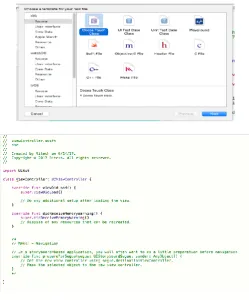
[image:2.595.308.558.330.631.2]C. After designing the view controller using assistant tools, the screen should be attached to the swift programming class called the coca touch class where the programming for the current screen can be done. Swift programming language consists of many data types, functions, variables, arrays, strings, and conditionals. By using these data types the programming can be done for the required application. D. After all the design procedure the app is tested by one of the tool in the X-code called simulator and this simulator shows the application same as in the iPhone and preview of the application can be seen.
Fig 2.1 Coca touch class in X-code
3. ANALYSIS OF BUILDING
© 2017, IRJET | Impact Factor value: 5.181 | ISO 9001:2008 Certified Journal
| Page 386
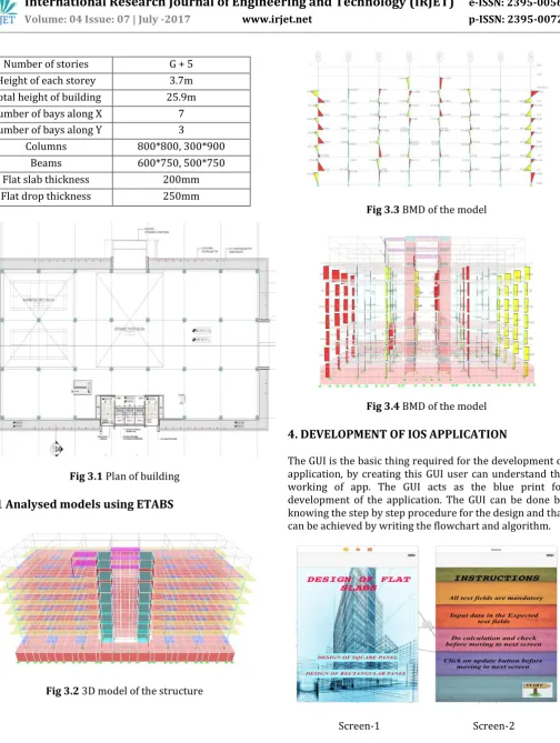
Fig 3.1 Plan of building [image:3.595.33.312.106.473.2]3.1 Analysed models using ETABS
Fig 3.2 3D model of the structure
Fig 3.3 BMD of the model
Fig 3.4 BMD of the model
4. DEVELOPMENT OF IOS APPLICATION
The GUI is the basic thing required for the development of application, by creating this GUI user can understand the working of app. The GUI acts as the blue print for development of the application. The GUI can be done by knowing the step by step procedure for the design and that can be achieved by writing the flowchart and algorithm.
Screen-1 Screen-2
To develop any program the flow chart is very important and it is step by step procdure to do the programming. Number of stories G + 5
Height of each storey 3.7m Total height of building 25.9m Number of bays along X 7 Number of bays along Y 3
[image:3.595.312.553.542.714.2]© 2017, IRJET | Impact Factor value: 5.181 | ISO 9001:2008 Certified Journal
| Page 387
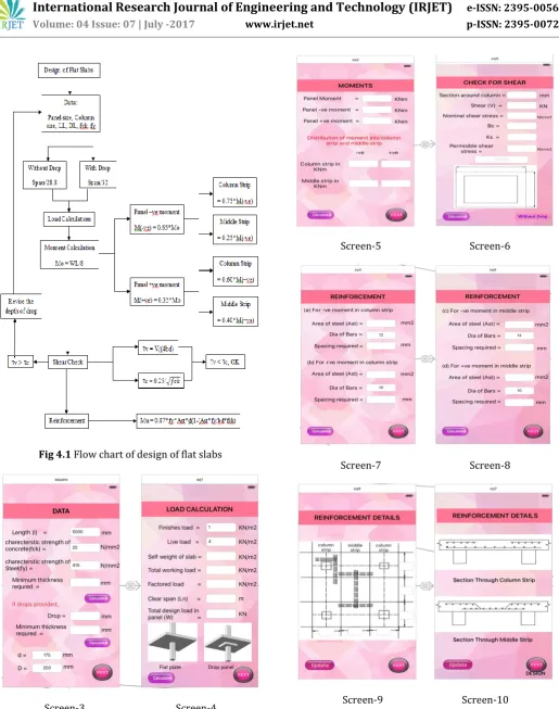
Fig 4.1 Flow chart of design of flat slabsScreen-3 Screen-4
Screen-5 Screen-6
Screen-7 Screen-8
[image:4.595.43.284.106.446.2]Screen-9 Screen-10
© 2017, IRJET | Impact Factor value: 5.181 | ISO 9001:2008 Certified Journal
| Page 388
4.1
Screens developed
Designs of square panel in flat slabs application have been developed in eight screens.
The GUI of the app is as shown in the fig. In the first screen all the data required are made to enter in the text fields.
In the second screen LL and DL required is made to enter and the self-weight of the slab, total working load, factored load and design load are calculated by writing the code in the assistant editor area. In the third screen, to calculate the panel moments,
moments in column strip and middle strip is designed.
In the fourth screen shear check is calculated. In the fifth and sixth screen reinforcement for the
required moments and spacing required for the bars are calculated.
Lastly in the seventh and eighth screen reinforcement detailing of the top view, section through column strip and section through middle strips are shown.
5. RESULTS AND DISCUSSIONS
The Flat Slab structure is modeled and analyzed using ETABS, by considering the span length of building as 8000mm, characteristics strength of concrete as 25 N/mm2, characteristics strength of steel as 500 N/mm2, drop of the slab 250mm, live load of the building 5 KN/m2 , and finishes
load as 3.5 KN/m2. Manual calculation of the flat slab is done
by using the same data considered for the analysis of the structure and then the results obtained from the manual calculation is compared with the application developed in IOS, Later the shear and reinforcement of the structure is checked in the application developed.
5.1 Flat Slab Design
LOADS
Self-weight=0.53*1*1*25=13.25KN/m2
Finishing load =3.5KN/m2
Live load = 5 KN/m2
TOTAL LOAD =21.75KN/m2
Design factored load =1.5*21.75=32.625KN/m2
Clear span =Ln=8-2.5=5.5m
Design load =WO=Wn*L2*Ln
=32.625*8*5.5=1435.5 KN
DESIGN TOTAL MOMENT
MO=WOLn/8= (1435.5*5.5)/8=986.90 KNm
Total –ve moment =0.65*986.90=641.48 KNm Total +ve moment=0.35*986.90=345.415 KNm
COLUMN STRIP MIDDLE STRIP
-ve moment 0.75*641.48 =481.11 KNm 0.25*641.48 =160.37 KNm
+ve moment 0.6*345.415 =212.6 KNm 0.4*345.415 =138.166 KNm
[image:5.595.307.561.222.649.2]5.2 Result From the Application Developed
Table 5.1: Detailing of the Slabs
Slab Dimens ion (m)
Slab Thickn ess (mm)
Drop Size (mm)
Reinforcement Column
Strip Middle Strip
S1 8*8 200 250
© 2017, IRJET | Impact Factor value: 5.181 | ISO 9001:2008 Certified Journal
| Page 389
S2 6.3*6.3 200 250
ᴓ10-281c/c ᴓ10-120c/c S3 8*6.3 200 250
ᴓ12-100c/c ᴓ10-150c/c
ᴓ10-208c/c ᴓ10-230c/c S4 7.5*6.3 200 250
ᴓ12-105c/c ᴓ12-110c/c
ᴓ10-215c/c ᴓ10-230c/c S5 8*7.5 200 250
ᴓ12-160c/c ᴓ10-120c/c
ᴓ10-170c/c ᴓ10-185c/c
6. CONCLUSIONS
1. With the use of IOS application the time taken for the design calculation for Flat Slabs is reduced. 2. With the use of IOS application the complexity
involved in design of Flat Slabs is reduced, since it is not required to know all the equations for the design process.
3. The IOS application is developed for both the square panel and rectangular panel structure.
4. The result obtained from the application has been compared with the standard problem given in the S.S.Bhavikati text book.
REFERENCES
[1] H.-S. Kim et.al, Efficient analysis of flat slab structures subjected to lateral loads Received 14 October 2003; received in revised form 7 October 2004; accepted 8 October 2004.
[2] M.G. Sahab et.al Cost optimization of reinforced concrete flat slab buildings (2004), engineering structures 27 (2005) 313-322.
[3] Sandesh D. Bothara International Journal of Engineering Research and
Applications (IJERA) Vol. 2, Issue 4, July-August 2012, pp.275-280.
[4] Prof. K S Sable, International Journal of Computer Technology and Electronics
Engineering (IJCTEE) Volume 2, Issue 3, June 2012.