© 2017, IRJET | Impact Factor value: 5.181 | ISO 9001:2008 Certified Journal
| Page 1550
COMPARATIVE STUDY ON REGULAR AND IRREGULAR RC STRUCTURES
UNDER FAR AND NEAR FIELD GROUND MOTION WITH BASE ISOLATION
SACHIN MANKAL
1, KARUNA S
21
M.TECH student, Dept. of Civil Engineering, The oxford college of engineering, Bangalore,
Karnataka, India
2
Assistent Professor, Dept. of Civil Engineering, The oxford college of engineering, Bangalore,
Karnataka, India
---***---Abstract - An Earthquake is characterized as the suddenmovement of Earth’s crust. Earthquakes are caused by the release of build-up stress within rocks along geological faults or by the movement of magma in volcanic territories. From previous Earthquakes it is seen that earthquakes results in mass destruction which further leads in loss of life. In order to overcome this and to build the Earthquake resistant structures base isolation technique can be used. In this thesis the comparative study on 20 storey regular and irregular RC frame structure under far and near field ground motion with and without base isolation is carried out. Nonlinear time history analysis is done using Kobe (HIK) and Bhuj earthquake data as far and near field ground motions respectively using ETABS 2013 FEM package. Lead rubber bearing (LRB) isolator is considered as isolation system where LRB is designed manually. The parameters considered for this study are base shear, storey displacement, acceleration, velocity, storey drift and time period. In this thesis the variation of parameters, for regular and irregular structure under far and near field ground motion with and without base isolation is studied.
Key Words: Lead rubber bearing (LRB), Near field
ground motion, Far field ground motion, Base isolation.
1. INTRODUCTION
An Earthquake is characterized as the sudden movement of Earth’s crust. Earthquakes are caused by the release of build-up stress within rocks along geological faults or by the movement of magma in volcanic territories. Major Earthquakes doesn’t happen much of the time, yet are generally damaging. Major earthquakes usually do not occur alone when one such earthquake happens there is usually another one at the nearby location. There are smaller earthquakes that occur in the same place before the larger earthquake follows. It causes various damaging effect at places they act. It causes severe damage to the buildings and great loss of life. Hence buildings under seismic prone regions should be designed such that it resists the earthquake without any failure. The sites which are nearer to the fault line are highly affected than the sites which are located far from the fault line.
1.1 Some important definitions
Fault: A fracture having significant movement in parallel with its plane is known as fault. The energy released during the quick slippage of faults results in earthquakes.
Near Field: The field or site which is in the range of 10km to 15km from the fault line is called as near field.
Far Field: When the distance of site or field is more than 20km from the fault line then it is called as Far Field.
The near field earthquake contains high frequency, long period, large amplitude pulses and higher accelerations when compared to far field ground motions. From the fluctuating nature of near field, evaluation of structural response is difficult. They are denoted by simple analogous pulse models of simplified motions composed of important near field aspects for their simplification.
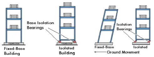
1.2 Base isolation system
A conventional method for making earthquake safe structures is to plan a firm and sufficiently solid structure with the goal that it could oblige expected lateral forces. This may not be the most cost effective technique. The issue with this method is that the building needs to assimilate all the horizontal forces prompted by the seismic ground motion.
© 2017, IRJET | Impact Factor value: 5.181 | ISO 9001:2008 Certified Journal
| Page 1551
Fig -1: Performance of Fixed Base and Isolated Basestructure
1.3 Classification of Base Isolation system
The devices are classified as 1. Elastomeric system. 2. Sliding system.
Elastomeric system is further classified as 1. Natural Rubber Bearings.
2. Lead Rubber Bearings.
3. High Damping Rubber Bearings.
Among these Elastomeric system Lead Rubber Bearing is used in this project
Lead Rubber Bearings
In contrast with natural rubber bearings, lead rubber bearings have a greatly improved ability to give sufficient stiffness to wind loads and better damping qualities.
The lead rubber bearing arrangement is the same as that of natural rubber bearings, apart from there is one cylindrical lead plugs in the center this along with rubber makes the device exhibit bilinear behavior. Under low service wind loads, high stiffness of the lead plug draws in the greater part of the load and the arrangement demonstrates high stiffness.
Fig -2: Lead Rubber Bearing
2. SCOPE OF THE STUDY
From previous Earthquakes it is seen that earthquakes results in mass destruction which further leads in loss of life. In order to overcome
this and to build the Earthquake resistant structures base isolation technique can be used.
Symmetrical structures impact in a similarly uniform distribution of seismic forces over its segments. Unsymmetrical structures result in uncertain distribution of forces. So the behaviour of regular structures over regular structure is studied. The sites which are nearer to the fault line are highly affected than the sites which are located far from the fault line.so the behaviour of structures under near field and far field ground motions are studied.
3. METHODOLOGY AND ANALYSIS
3.1 DETAILS OF PLAN
The plan has 5 x 4 bays, length of each bay is considered as 4m. SMRF (Frame) of 20 storey with regular and irregular in plan is considered. The storey height is same for all the building models considered for analysis.
3.2 PARAMETERS CONSIDERED FOR ANALYSIS
1. Type of structure: Special Moment resisting frame 2. Number of stories: 20
3. Earthquake Zone: V (as per IS 1893:2000) 4. Floor to floor height: 3m
5. Concrete grade: M30 6. Grade of steel: Fe 500 7. Column: 400mm x 700mm 8. Beam: 200mm x 500mm 9. Slab depth: 175mm
10. Super dead load (floor load): 1.5 kN/m2(as per IS 875
(Part 1))
11. Live load: 3 kN/m2(as per IS 875 (Part 2))
12. Live load on top floor: 1.5 kN/m2(as per IS 875 (Part 2))
13. Super dead load (floor load) on top floor: 0.75 kN/m2(as
per IS 875 (Part 1))
14. External wall Load: 10kN/m 15. Parapet wall load (1m): 4kN/m
16. Importance factor: 1(as per IS 1893:2000)
17. Response reduction factor: 5 (as per IS 1893:2000)
3.4 MODEL DESCRIPTION
The plan and Elevation of models considered are as follows:
Model R1: Regular structure with Fixed Base. Model R2: Regular structure with Isolated Base. Model IR1: Irregular structure in which projection
provided are 40% and 50% in X and Y directions respectively with Fixed Base.
[image:2.595.60.268.577.674.2]© 2017, IRJET | Impact Factor value: 5.181 | ISO 9001:2008 Certified Journal
| Page 1552
Model IR3: Irregular structure in which projection provided are 40% and 50% in X and Y directions respectively with Isolated Base.
Model IR4: Irregular structure in which projection provided are 60% and 50% in X and Y directions respectively with Isolated Base.
Model R3: Regular structure with Fixed Base. (Far Field)
Model IR5: Irregular structure in which projection provided are 40% and 50% in X and Y directions respectively with Fixed Base. (Far Field)
Model IR6: Irregular structure in which projection provided are 60% and 50% in X and Y direction respectively with Fixed Base. (Far Field)
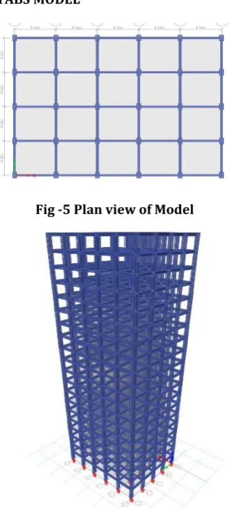
[image:3.595.79.244.282.649.2]3.5 ETABS MODEL
[image:3.595.327.561.310.584.2]Fig -5 Plan view of Model
Fig -6 Isometric view of Model
The dynamic (Time history) analysis of G+20 storey RC framed structure is carried out using “ETABS 2013” software, Loading is applied as per IS1893-2000 and IS:875 (part 2). Bhuj earthquake data is used for analysis of structure as near field and Kobe HIK earthquake record is used for analysis under far field.
After the analysis of the structure the LRB Base isolator is designed by considering the maximum Base reaction obtained from the analysis of fixed base structure using ETABS 2013 software.
3.6 Design of Base Isolator (As per UBC 1997 & IS 1893-2000)
Lead rubber bearing type of isolator is used for analysis of the structure and to find the properties of LRB the design is carried out.
3.7 Codal Provisions for Design of Base Isolator
The LRB Base Isolator is designed as per UBC-1997 and IS 1893-2000.Some of the important data required for the Design of LRB are:
1. Seismic zone Factor (Z) = Zone V (Table 16I UBC 1997)
2. Soil profile type = Sc (Table 16J UBC 1997) 3. Seismic coefficient (Ca) = 0.36 (Table 16Q UBC
1997)
4. Seismic coefficient (Cv) = 0.54 (Table 16R UBC 1997)
5. Importance Factor ( I ) = 1 (Table 16K UBC 1997)
6. Response reduction factor (R) = 5 (Table 16N UBC 1997)
7. Seismic Source type = B (Table 16U UBC 1997) 8. Damping Coefficient ( Bd) = 1(Table 16C UBC 1997) 9. Damping Coefficient (Bm) = 1 (Table 16C UBC
1997)
10. Near source factor (Na) = 1 (Table 16S UBC 1997)
11. Near Source factor (Nv) =1 (Table 16T UBC 1997)
12. Damping Beff = 5% ( From IS 1893-2000 for RC structures )
13. Weight of the structure (W) = 7036 KN ( From Analysis)
The Design procedure of LRB base isolator is referred from DESIGN OF SEISMIC ISOLATED STRUCTURE by James M.Kelly and Farzad Naeim.
STEP 1: Calculation of Design displacement (Dd)
Assume design time period as Td = 2.5 seconds. g = 9.81
STEP 2: Calculation of Effective Stiffness (Keff)
STEP 3: Calculation of Energy dissipated per cycle (Wd)
© 2017, IRJET | Impact Factor value: 5.181 | ISO 9001:2008 Certified Journal
| Page 1553
STEP 5: Calculation of Stiffness in rubber (K2)
STEP 6: Calculation of Yield Displacement (Dy) We know that K1= 10K2
STEP 7: Recalculation of Q to Qr STEP 8: Calculation of area & Diameter of Lead Plug (Assume Yield strength of lead core in between 7 to 8.5 Mpa) Area of lead plug needed is
where( σypb = 8.5Mpa) Diameter of lead plug is
STEP 9: Revising rubber stiffness Keff to Keff(R)
STEP 10: Total thickness of rubber layer (tr)
Where = 100% (Max shear strain of rubber) STEP 11: Area of Bearing (Alrb)
G = Shear modulus of rubber (Ranging between 0.4 to 1.1 Mpa)Adopt G = 0.8 Mpa STEP 12: Diameter of Bearing (
STEP 13: Shape Factor (S)
Take horizontal Period to be 2.5 seconds fh = fh = 0.4 HZ fv = 10HZ
W.K.T Where t is thickness of single rubber layer
Number of rubber layers =
STEP 14: Dimensions of lead rubber Bearing (LRB) Let the thickness of shim plates be 3mm
Number of shim plates = (No of rubber layers -1) End plate thickness is between 19.05mm to 38.1mm Therefore adopt 35mm as thickness of End plate. STEP 15: Compression Modulus Ec
Where K = 2000 Mpa
STEP 16: Horizontal stiffness (Kh)
STEP 17: Vertical stiffness (Kv)
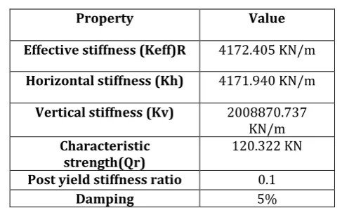
Property Value
Effective stiffness (Keff)R 4172.405 KN/m
Horizontal stiffness (Kh) 4171.940 KN/m
Vertical stiffness (Kv) 2008870.737 KN/m Characteristic
strength(Qr) 120.322 KN
Post yield stiffness ratio 0.1
[image:4.595.311.555.93.241.2]Damping 5%
Table-1 Properties of LRB required in Etabs 2013
4. RESULTS AND DISCUSSIONS
This section presents the results and discussions of seismic analysis of regular and irregular RC structure under near field and far field ground motion with base isolation considering very extreme seismic zone (Zone V), The results of Nonlinear dynamic analysis of regular and irregular RC structure under near field and far field ground motion with base isolation has been discussed below.
1. Base Shear
2. Maximum storey displacement 3. Storey drift
4.1 Base Shear
Fig -8 Base shear for R1, R2, IR1, IR3, IR2 and IR4 in X direction
© 2017, IRJET | Impact Factor value: 5.181 | ISO 9001:2008 Certified Journal
| Page 1554
COMPARISION AND DISCUSSION From the figures it is observed that the base shear for regular model (R1) is maximum and the base shear is reduced in irregular models IR1 and IR2 (re-entrant corners offset is increased).
When the Fixed base models(R1,IR1,IR2) and Isolated base models(R2,IR3,IR4) are compared, base shear in isolated base is reduced by 45% in both X and Y directions.
When the the structure under near field ground motion is compared with strucutre under far field ground motion base shear is very negligible under far field ground motion in both X and Y directions.
MODEL X Direction Y Direction BASE SHEAR (KN) R1 2918.817 2561.228 R2 1576.16 1383.16 R3 148.833 269.981 IR1 2260.464 2117.245 IR2 1953.576 1807.932 IR3 1243.255 1164.48 IR4 1094.002 1012.85 IR5 132.7903 229.2232 IR6 120.7655 199.3618
Table-2 Base shear for all the models
4.2 MAXIMUM STOREY DISPLACEMENT
Fig-11 Maximum storey displacement for R1, R2, IR1, IR3, IR2 and IR4 in X direction
Fig-12 Maximum storey displacement for R1, R3, IR1, IR5, IR2 and IR6 in X direction
COMPARISION AND DISCUSSION
From figures it is witnessed that the storey displacement increases as the elevation of the structure increases and when comparing the irregular model with the regular one the displacement insreases with increase in irregularity in both X and Y directions.
The displacement in isolated base structure is more than the fixed base structure in both X and Y direction due to isolator.
When the structure under near field ground motion is compared with strucutre under far field ground motion storey displacement is very negligible under far field ground motion in both X and Y directions.
MODEL X Direction Y Direction DISPLACEMENT (MM)
R1 110.8 89.4
R2 137 120.5
R3 6.1 4.8
IR1 125.4 111.7
IR2 140.9 128.2
IR3 148.3 136.1
IR4 162.6 152.1
IR5 6.8 6.1
IR6 8 7.4
Table-3 Maximum storey displacement values for all the models
4.2 STOREY DRIFT
© 2017, IRJET | Impact Factor value: 5.181 | ISO 9001:2008 Certified Journal
| Page 1555
Fig-14 Maximum storey displacement for R1, R3, IR1,IR5, IR2 and IR6 in X direction
COMPARISION AND DISCUSSION
From the storey drift plot it is observed that in all the models with fixed base and isolated base under near field ground motion, the drift is maximum at storey 11 in X direction.
From Fig13 it is observed that the drift is maximum in model IR2 along X direction
When the structure under near field ground motion is compared with strucutre under far field ground motion storey drift is very negligible under far field ground motion in both X and Y directions.
5. CONCLUSION
The base shear of regular model is maximum and the base shear is reduced in irregular models. When the Fixed base models and Isolated base
models are compared, base shear in isolated base is reduced by 45% which increases the stability of the structure.
Base shear of structures under far field ground motion is very less when compared to structures under near field ground motions.
The storey displacement increases with increase in storey, and the displacement insreases with increase in irregularity in both X and Y directions. The displacement of structure with base isolation is
greater than the structure with fixed base.
The displacement of structure under far field ground motion is very negligible when compared with near field ground motion.
The acceleration and velocity of regular structure is greater than the irregular structure, whereas the displacement is maximum in irregular structure. Due to base isolation the acceleration and velocity is
reduced in isolated structures when compared to fixed base structure.
Acceleration and velocity of structure under near field ground motion is greater than the structures under far field ground motion.
6. REFERENCES
1. C.P. Providakis (2007), Effect of LRB isolators and supplemental viscous dampers on seismic isolated buildings under near-fault excitations.
2. Ms. Minal Ashok Somwanshi and Rina N Pantawane (2015), Seismic Analysis of Fixed Based and Base Isolated Building Structures.
3. Vinodkumar Parma, G.S.Hiremath (2014), Effect of base isolation in multistoried RC irregular building using time history analysis.
4. Syed Ahmed Kabeer K I, Sanjeev Kumar K.S (2014), Comparison of Two Similar Buildings with and without Base Isolation.
5. H. R. Tavakoli, H. Gilani & G. R. Abdollahzadeh (2012), Comparative Evaluation of Seismic Parameters for Near-Fault and Far- Fault Earthquakes.
6. A. GHOBARAH (2004), Response of structures to near-fault ground motion.
7. VENKATESH, Mr.ARUNKUMAR.H.R (2016), Dynamic ananysis of 11 storey rc structure by providing lead rubber bearing as base isolation system.
8. M. Davoodi, M. Sadjadi & P. Goljahani, M. Kamalian (2012), Effects of Near-Field and Far-Field Earthquakes on Seismic Response of SDOF System Considering Soil Structure Interaction.
9. Reza S. Jalali, Mohammad Nouripour Azgomi, Mihailo D.Trifunac (2013), In-plane response of two-story structures to near-fault ground motion. 10. James M.Kelly and Farzad Naeim, Design of Seismic
Isolated Structure from theory of practice, John Wiley and sons, 1999.
11. IS: 456-2000, “Code of Practice for Plain and Reinforced Concrete”, Bureau of Indian Standard, New Delhi, India.
12. James M Kelly, Earthquake resistant Design with Rubber, Springer-Verlag, 1st edition, 1993. 13. IS 1893 (Part 1): 2002, “Criteria for Earthquake
Resistance Design of Structures”, part 1General Provisions and Buildings, fifth revision, Bureau of Indian Standards, New Delhi, India.
14. Uniform Building Code. International Conference of Building Officials. Whittier, CA. 1997.
15. IS 875-2: Code of Practice for Design Loads (Other Than Earthquake) For Buildings And Structures.
7. BIOGRAPHIES