© 2018, IRJET | Impact Factor value: 6.171 | ISO 9001:2008 Certified Journal | Page 3393
The Rehabilitation Techniques for Irwin Bridge
Anirudha Patil¹, Tushar Naik², Vaibhav Mohite³, Deepak Sharma⁴, Prof. Chaitali Chimanna⁵
1,2,3,4,5 Vishveshwarya Technical Campus, Patgaon, Miraj.
---***---Abstract -- The rehabilitation techniques provide an attractive and economical solution for strengthening masonry arch bridge to increase their stability. Bridges have been important throughout history in connecting cultures, sharing ideas, and providing the backbone of transportation networks. It is necessary to restore and preserve these structures for their particular functionality and cultural heritage value. The focus of this paper is to present and discuss the many ways of strengthening and repairing masonry arch bridge ranging from minimum intervention to complete reconstruction. It is meant to provide a guide for engineers and architects on the methods available and the advantages and disadvantages of these methods, and to assist in their decisions of masonry arch bridge conservation. The main focus is on understanding and comparing different methods of strengthening and repairing masonry arch bridge.
Keywords-VisualInspection1Rehabilitation Techniques2 Irwin Bridge3
1. INTRODUCTION
In India before some years ago there are many masonry structures were constructed. Irwin bridge is also masonry arch bridge structure constructed in 1929 at Sangli city. The bridge was constructed for many different purposes like transport, trading, aesthetics of river etc. The Irwin bridge was constructed 90years ago so that, The development of a variety of strengthening and repairing techniques has been necessary for historical masonry bridge. Particularly the many causes of degradation, different failures, and needs for upgrading load-bearing capacity must be considered in defining the Conservation works needed for a bridge. In this paper the rehabilitation techniques are suggested by the use of conditional survey of bridge.
The general information of Irwin bridge:
Total height of Bridge = 70 ft from bed level No. of Span = 13, each span of 50ft
outer to outer distance
Total length of Bridge = 819ft Carriage way = 20ft
Footpath = 3ft both side
Arch Rise = (1/5) ratio (to the span length)
Pier = 12ft wide, 55ft height, at bottom 8ft circumference
Abutment = 14ft thick
Location of Irwin Bridge
1.1 What is rehabilitation?
Rehabilitation is the process of restoring the structure to service level, once it had and now lost, strengthening consists in endowing the structure with a service level, higher than that initially planned by modifying the structure not necessarily damaged structure.
It is evident that rehabilitation of bridges involves addressing a myriad of problems and no single technique or retrofit method could offer a complete solution. Therefore, answer lies in being able to address each individual problem with an appropriate technique to result in a durable retrofit. This article aims at providing an overview of a variety of structural retrofit techniques available to rehabilitate bridge
1.2 METHODOLOGY
A. To conduct condition survey of bridge
Analyze the data and prepare checklist for condition survey. Also, other required documentation to be prepared.
In Visual Inspection of the Bridge- A survey of the Bridge can reveal the Following:
1. Cracks in deck slabs, piers and abutments. 2. Concrete disintegration and exposed steel reinforcements photographs can be helpful.
3. To reveal deterioration in concrete by slight tapping using hammer.
© 2018, IRJET | Impact Factor value: 6.171 | ISO 9001:2008 Certified Journal | Page 3394 6. Cracks in wing walls indicating swelling in members or
corrosion and lose joints.
7. Leakages from different part of bridge. 8. Deficiencies in arch of bridge.
8. Damages in different joints of bridge.
B. To detect damages
By using visual inspection detect the damages and inspect level of damage
2. Rehabilitation techniques on basis of condition survey of bridge
A. Pier and spandrel wall
Fig1-:Cracks and loosening of joints
Problem: Areas of cracking to be detected in pier and spandrel wall
Rehabilitation techniques
Cellular Foamed Cement Grouting
To facilitate grouting, 12-mm (0.5-in.) diameter holes were drilled through mortar joints within the exposed below-grade masonry to terminate within the inner-core rubble. Injection tubes were then installed into the holes and the masonry ‘rough-parged’ to facilitate containment of the fluid grout during the subsequent core stabilization work.
A cellular foam grout was then mixed and pumped through the injection tubes to fill any voids within the inner core rubble of the masonry. This part of the restoration strategy was designed to further stabilize the foundation walls and provide for a more uniform load distribution across the cross-section of the masonry assembly. The cellular grout was selected for its beneficial load absorbing characteristics, as well as its low-strength and lightweight properties.
A methyl cellulose-type admixture was combined with the cement/water grout to provide thixotropic properties to the plastic grout, minimizing leakage to the interior through cracks and gaps. To generate the foam, a proprietary surfactant-type admixture was diluted in water
and forced through a nozzle when fed from a pressurized steel cylindrical tank. The nozzle end was fitted with a pressure gauge, shut-off valve and a return line, which allowed control of the flow of grout and pumping pressures at the grout injection point.
Fig2-: cellular foamed cement grouting
B. Abutment:
Fig3-: Delamination of stones in abutments
Problem: The most common problem observed during inspection of abutment are vertical movement, scour and under mining of the foundation, drainage system malfunction, materials defects, presence of excessive or unexplained moisture at or behind the abutments etc. Also, it is most affected part of bridge.
Rehabilitation technique:
the delaminated stones are replaced using new stones. They are properly fixed by using concrete masonry with adding admixtures to it. The joints are filled properly with concrete mortar. Proper finishing is provided to surface of abutment.
© 2018, IRJET | Impact Factor value: 6.171 | ISO 9001:2008 Certified Journal | Page 3395 Concrete Apron Wall
A concrete apron wall can be utilized as a permanent structural repair for abutments that have experienced scour. For this repair, a concrete wall is cast against the stream side of the abutment and extended down at least eight feet. Riprap is typically utilized as another means of protection against future scour. Special attention should be paid to the riprap placement. The riprap will help to ensure that the new apron wall is not undermined due to scour. The lost soil below the abutment should also be filled with concrete in order to reintroduce bearing capacity.
Fig5: - Concrete apron wall
C. Deck slab
[image:3.595.36.285.308.514.2]
Fig.6:-Spallingof concreteof deck slab
Problem:
The bottom joint of deck slab is damaged and loose joint sections. There is deteriorated mortar at the edges of the joint of deck slab and spandrel wall. Stones are loosening at joint section decreasing bonding between deck & wing wall.
Rehabilitation technique:
All loose, disintegrated and unsound concrete shall be removed from portions of the deck slab. There shall be take care not to damage reinforcement bars or expansion joints which are to remain in place. Any damage to reinforcement bars or expansion joints shall be corrected.
Areas to be repaired will be determined and marked. A concrete saw shall be used to provide vertical edges approximately 3/4 in. (20 mm) deep around the perimeter of the area to be patched when a concrete overlay is not
specified. Where high steel is present, the depth may be reduced. A saw cut will not be required on those boundaries along the face of the curb, parapet or joint or when sharp vertical edges are provided by hydro-demolition.
The loose and unsound concrete shall be removed by chipping, with power driven hand tools or by hydro-demolition equipment. All exposed reinforcing bars and newly exposed concrete shall be thoroughly blast cleaned. Where the bond between existing concrete and reinforcement steel within the patch area has been destroyed, the concrete adjacent to the bar shall be removed to a depth that will permit new concrete to bond to the entire periphery of the exposed bar. A minimum of 1 in. (25 mm) clearance will be required. There may be require enlarging a designated removal area should inspection indicate deterioration beyond the limits previously designated. In this event, a new saw cut shall be made around the extended area before additional removal is begun. The removal area shall not be enlarged solely to correct bonded reinforcement or deficient lap lengths.
Reinforcement Treatment
The Care shall be exercised during concrete removal to protect the reinforcement bars and structural steel from damage. Any damage to the reinforcement bars or structural steel to remain in place shall be repaired or replaced. All existing reinforcement bars shall remain in place except as herein provided for corroded bars. Tying of loose bars will be required. Reinforcing bars which have been cut or have lost 25 percent or more of their original cross-sectional area shall be supplemented by new in-kind reinforcement bars. New bars shall be lapped a minimum of 32 bar diameters to existing bars. An approved mechanical bar splice capable of developing in tension at least 125 percent of the yield strength of the existing bar shall be used when it is not feasible to provide the minimum bar lap. No welding of bars will be permitted.
Immediately after completion of the concrete removal and reinforcement repairs, the repair areas shall be cleaned of dust and debris. Once the initial cleaning is completed, the repair areas shall be thoroughly blast cleaned to a roughened appearance free from all foreign matter.
Placement & Finishing of Concrete Repair
The patch area shall be cleaned and shall be thoroughly wetted and maintained in a dampened condition with water for at least 12 hours before placement of the concrete. Any excess water shall be removed by compressed air or by vacuuming prior to the beginning of concrete placement. Water shall not be applied to the patch surface within one hour before or at any time during placement of the concrete.
© 2018, IRJET | Impact Factor value: 6.171 | ISO 9001:2008 Certified Journal | Page 3396 Other damages
1.River Bank
Fig7:- absence of training wall in river bed
Problem
The size of the river bed goes on increasing due to absence of training wall on western side.
Rehabilitation techniques
The purpose of river training is to stabilize the river channel along the certain alignment with a certain cross section. we suggest the following methods for Krishna River Bank.
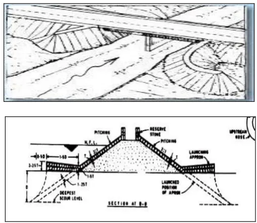
Guide Banks:
Guide banks are artificial embankments constructed along the flow direction both upstream and downstream of the abutment on one or both sides of the river for guiding the river flow past a bridge (or other hydraulic structures, such as weirs or barrages) without causing damage to the bridge and its approaches.
The overall waterway between guide banks is obtained by adding thickness of piers to the clear waterway. Figure 9.4 shows the plan and section of a typical guide bank. The elevation of the top of the guide banks is kept 1.5 to 2.5 m above the HFL of 100-year flood.
The top width of guide banks is generally kept between 6 and 9 m. Locally available earth materials are used for
constructing guide banks. To prevent erosion of the material from the river-side surface of guide bank, the surface is stone-pitched.
Fig 8:- Guide Bank
Bank Protection:
Bank failures due to either wave action or erosive action of river flow can lead to river breach causing huge losses in terms of human lives, property, agriculture and other utilities. Measures of bank protection such as revetment, riprap, etc. provide a shield against erosion of bank material. Bank revetments are mattresses of suitable material, such as reinforced asphalt and articulated concrete, laid over the bank surface to be protected.
Riprap of hard angular rock fragments (or concrete blocks) laid on a thick layer of rubble or quarry chips is cheap and durable method of bank protection. Another way of providing bank protection is by means of flexible brick pitching
For this purpose, bricks having a pair of holes across their full width are laid on the bank slope and for some distance on the river bed at the toe of the bank. A G.I. wire passes through the brick holes. The wires are knotted at their ends and suitably anchored so that the bricks are held together and also small movement of bricks is possible.
[image:4.595.305.559.125.345.2]© 2018, IRJET | Impact Factor value: 6.171 | ISO 9001:2008 Certified Journal | Page 3397 Embankments:
The floods may be prevented from submerging the country by constructing earth embankments. They are generally constructed up to a height of 12 m. They are designed and constructed in the same way as an earth dam. The embankments are generally constructed parallel to the river channel.
Types of embankments are
i. Marginal embankments or dykes or levees, ii. Retired embankments.
i. Marginal embankments or dykes or levees,
The marginal embankments are constructed as close to the banks as possible to restrict the flood water from submerging the area behind them. Figure shows the position of marginal embankments. They are designed to hold up the water up to a maximum anticipated HFL without the possibility of overtopping and with a view to withstand all external pressures. This condition is met with by providing sufficient freeboard, bed width, top width and stone protection on adequate slopes.
Fig9:- Marginal embankments or levees
ii. Retired embankments.
Retired embankments are constructed at a distance from the river banks. Thus, retired embankments are the intermediate type between the case of marginal embankments and river with no embankments. Retired embankments are generally constructed on a lower ground away from the banks.
2. Gallery of bridge
Fig11:-Gallery of bridge
Problem
The components of gallery of bridge gets eroded. There is corrosion formed at stairs of gallery. Erosion and loosening of joints in gallery of bridge.
Rehabilitation techniques
The rehabilitation techniques or repairs for gallery are not suitable due to very severe damages are occurred. So, it is necessary to reconstruct the gallery of bridge.
III. CONCLUSION
1.Works of strengthening and repair are concerned with the restoration of the stability, integrity and durability of the structure together with the bridges return to service.
2.Regular general maintenance of a bridge is also important in preserving the integrity and stability and preventing further damages from incurring. By following a logical and careful process of bridge conservation and using repairing and strengthening techniques that follow conservation guidelines such as those presented in this paper, successful intervention which respects the needs for performance improvements and cultural preservation may be performed.
3.commonly used retrofitting techniques for masonry arch bridges and finally the suggestions regarding the description of retrofitting and preserving bridge side by side adopting suitable techniques along with their respective pictures.
4.In case of extreme unrepairable cracks and other damages, we can conduct rebuilding technique with every step of carefulness and alertness so that it does not affect the identity of the historic structures.
5.The retrofitting techniques has been discussed in this Project for Irwin Bridge are the personal suggestions after understanding the level of damages in bridge, studying the image of particular bridge.
ACKNOWLEDGEMENT
The authors can acknowledge any person/authorities in this section. This is not mandatory.
This research was supported by Prof. C.R. Chimanna, Prof. A.A.Mahajan , and Prpf. V. G. Awasare . VTC patgaon, Miraj. We are thankful to our colleagues from Civil Department, who provided expertise that greatly assisted the research.
© 2018, IRJET | Impact Factor value: 6.171 | ISO 9001:2008 Certified Journal | Page 3398 REFERENCES
1) Study of literat Atkins (2010) “Structures Condition Survey of BPRN” London Bridges Engineering Group.
2) Bhaskar S, Chellappan A, Prabakar J, and Srinivasan P, (2007, 1973) “A review on ‘Different bond test procedures and bond behaviour of rebars in concrete”, SERC Research Report No. MLP-12841-RR-02, September, 2007. Indian Standard Methods of testing bond in reinforced concrete (Part I Pullout test), IS: 2770-1967, Indian Standards Institution, New Delhi. RILEM/CEB/FIP Recommendation, “Bond test for reinforcing steel”, Materials and Structures, 6(32), (1973), 97-105.
3) James A. Kerns, P.E.(1995) “What is Conditional Survey” Real State Journal, 1995, ACI SP-153, 25-42.
4) Krishnamoorthy T.S., Gopalakrishnan S., Balasubramanian K., Bharatkumar B.H., and Rama Mohan Rao. P., (2002) “Investigations on the cementitious grouts containing supplementary cementitious materials”, International Journal of Cement and Concrete Research, 32(9), (2002), 1395-1405. Product information sheets, Elkem materials, 2008.
5) Maria Rashidi, Peter Gibson (2011) “A Methodology for Bridge Condition Assessment” Australasian Transport Research Forum 2011, Proceedings 28 - 30 September 2011, Adelaide, Australia.
6) Springfield Illinois Publication (2011) “Bridge Condition Report Procedures & Practices” BCR Procedures & Practices – Revised December 2011. 7) Vinod Bolle1, Prof. Santhosh Kumar Banoth(2016) “Review On Railway Bridge &Track Condition Monitoring System” International Journal of Advance Research, Ideas and Innovations in Technology ISSN: 2454-132X (Volume2, Issue4).
BIOGRAPHIES
Mr. Anirudha Patil, pursuing B.E. in civil Engineering at Vishveshwarya Technical Campus, Patgaon, Miraj.
Mr. Tushar Naik, pursuing B.E. in civil Engineering at Vishveshwarya Technical Campus, Patgaon, Miraj.
Mr.Deepak Sharma, pursuing B.E. in civil Engineering at Vishveshwarya Technical Campus, Patgaon, Miraj.