© 2017, IRJET | Impact Factor value: 5.181 | ISO 9001:2008 Certified Journal | Page 937
Fixed Width Replica Redundancy Block Multiplier
1
Mr.K V K V L PAVAN KUMAR,
2Mrs.G L SRAVANTHI
1
Assistant professor, Department of ECE,
2Assistant Professor, Department of CSE, VNITSW,
JNTU Kakinada, AP, India.
---****---
Abstract
—
In this paper, we propose a fixed-widthmultiplier design by using versatile noise tolerant ANT architecture that helps to build fixed-width multiplier with reduced precision replica redundancy block (RPR). The proposed architecture can achieve high precision, low power consumption, and area efficiency. We provide fixed-width RPR with error compensation circuit using the partial product terms of input correction vector to lower the prune errors, the hardware for error compensation circuit is simple. In a 12 × 12-bit multiplier, area of fixed-width RPR can be lowered by 44.55% and power consumption is saved by 23% as compared with the existed ANT design.
Index Terms— Algorithmic noise tolerant (ANT), fixed-width multiplier, reduced-precision replica (RPR), voltage overscaling (VOS).
1.INTRODUCTION
In recent years, the rapid growth for portable wireless computation devices enhances the requirement for ultralow power devices. To reduce the power dissipation, voltage scaling is heavily used as an accurate low-power technique because the power consumption in CMOS circuits is directly related to the square of voltage [1]. However, in deep-submicrometer process technologies, noise problems have faced difficulty to design the reliable and accurate microelectronics systems; hence, these designs are developed to intensify noise tolerance. [2]–[12].
A hostile low-power technique, called voltage overscaling (VOS), was introduced in [4] to lower voltage beyond critical supply voltage without surrendering the throughput. However, VOS degrades signal-to-noise ratio (SNR). A novel (ANT) technique [2] combined VOS block with reduced-precision replica (RPR), which removes soft
errors accurately and saves energy Some ANT deformation designs are proposed in [5]–[9] and the ANT design is further extended to system level in [10]. Whereas, the RPR in the ANT designs of [5]–[7] are designed in a organized manner, which are not easily versatile.
[image:1.595.314.542.202.347.2]The RPR designs in the ANT designs of [8] and [9] can operate with high speed, but their hardware complexity is high.
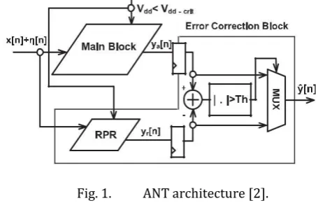
Fig. 1. ANT architecture [2].
The RPR design in the ANT design of [2] is the most liked design because of its simple circuitry. Whereas, ANT with RPR in [2] have high area overhead and power consumption. In this paper, we proposed an easy fixed-width RPR that replace the full-fixed-width RPR block in [2]. Using the fixed-width RPR, the computation error can be corrected with low power consumption and low area overhead.
In order, to decrease the critical path delay, we restrict the compensation circuit in RPR must not be used in the critical path. As a result, we can analyze the ANT design with smaller area, lower power consumption, and lower critical supply voltage.
II.ANT ARCHITECTURE DESIGN
The ANT technique [2] uses both main digital signal processor (MDSP) and error correction (EC) block, as shown in Fig. 1. To achieve ultralow power, VOS is used in MDSP. Under VOS, if the critical path delay Tcp becomes greater than
the sampling period Tsamp, the soft errors may occur. It
degrades signal precision. In the ANT [2], a replica of the MDSP but with reduced precision operands and shorter operation delay is used as EC block. In VOS, there are many number of input dependent soft errors in its output ya[n]; however, RPR output yr[n] is still correct since the critical path delay of the replica is smaller than Tsamp [4]. Hence, yr[n] is used to detect errors in the MDSP output ya[n]. instead of ya[n]. As a result, y ˆ[n] can be given as
© 2017, IRJET | Impact Factor value: 5.181 | ISO 9001:2008 Certified Journal | Page 938
and..…(2)
where yo[n] is error free output signal. In this way, the power consumption is highly reduced while the SNR is maintained without severe degradation [2].
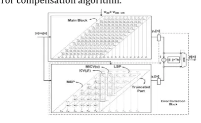
Fig. 2. Proposed ANT architecture with fixed-width RPR.
III. PROPOSED ANT MULTIPLIER DESIGN
USING FIXED-WIDTH RPR
In this paper, we proposed the fixed-width RPR to replace the full-width RPR block in the ANT design [2], as shown in Fig. 2, which can provide high precision, low power consumption, and lower area overhead in RPR, but also operate with high SNR, more area efficient, low supply voltage. In analyzing the ANT architecture, we manifest our fixed-width RPR-based ANT design in an ANT multiplier.
The fixed-width is usually used in DSP applications to prevent infinite growth of bit width. Cutting off n-bit least significant bit (LSB) output is a famous solution to design a fixed-width DSP with n-bit input and n-bit output. The hardware complexity and power consumption of a fixed-width DSP is very less. However, the truncation of LSB part results in rounding error, that require compensated precision. Many literatures [13]–[22] are presented to minimize the truncation error with constant correction value [13]–[15] or with variable correction value [16]–[22].
The circuit complexity to compensate with constant corrected value is simple than that of variable correction value; however, the variable correction approach is highly precise. In [16]–[22], the compensation method is to compensate the truncation error between the full-length multiplier and the fixed-width multiplier.
In fixed-width RPR of an ANT multiplier, the compensation error is to correct the overall truncation error of MDSP block. Nowadays, there are many fixed-width multiplier designs applied to the full-width multipliers but
there is no fixed-width RPR applied to the ANT multiplier designs.
To achieve high precise error compensation, we compensate this truncation error with variable correction value. We design the error compensation circuit using the partial product terms with the largest weight in the least significant segment. In order to save hardware complexity, the compensation vector in the partial product terms with the large weight in the least significant position is directly injected into the fixed-width RPR, which does not require extra compensation logic gates [17].
To minimize the compensation error, we also consider the impact of truncated products with the second most significant bits on the error compensation. We proposed an error compensation circuit using a simple minor input correction vector to compensate the error remained. In order, to decrease the critical path delay, we place the compensation circuit in the noncritical path of the fixed-width RPR. As compared with the full-width RPR design in [15], the proposed fixed-width RPR multiplier operates with high SNR, lower circuitry area and low power consumption.
A. Proposed Precise Error Compensation Vector
for Fixed-Width RPR Design
In an ANT design, RPR is used to correct the errors that occurs at the output of MDSP and maintain the SNR of whole system without lowering supply voltage. In the case of fixed-width RPR to analyse ANT architecture, we lower circuit area and power consumption, and enhance the computation speed compared with the conventional full-length RPR. However, we require to compensate large truncation error due to cutting off many hardware elements in the LSB part of MDSP.
In MDSP of n-bit ANT Baugh–Wooley array multiplier, its two-unsigned n-bit inputs of X and Y can be related as
………(3)
The product result P is the summation of partial products of xi y j, which is expressed as
……(4)
© 2017, IRJET | Impact Factor value: 5.181 | ISO 9001:2008 Certified Journal | Page 939
are most significant part (MSP), input correction vector[ICV(β)], minor ICV [MICV(α)], and LSP, as shown in Fig. 3. In fixed width RPR, only MSP part is kept and all other subsets are eliminated. Hence, the remaining three parts of ICV(β), MICV(α), and LSP are called as truncated part. The truncated ICV(β) and MICV(α) are the most important parts because of its highest weight.
[image:3.595.44.248.211.336.2]Therefore, they can be used to design the truncation error compensation algorithm.
Fig. 3. 12 × 12-bit ANT multiplier is implemented with the six-bit fixed width replica redundancy block.
To caluclate the efficiency of a fixed-width RPR, we provide the difference between the (n/2)-bit fixed-width RPR output and the 2n-bit full-length MDSP output, which is expressed as
ε = P – Pt ………… (5)
where P is the output of the complete multiplier in MDSP and
Pt is the output of the fixed-width multiplier in RPR. Pt can be expressed as
…………..(6)
where f (EC) is the error compensation function, f (ICV) is the error compensation function contributed by the input correction vector ICV(β), and f (MICV) is the error compensation function contributed by minor input correction vector MICV(α).
Therefore, the proposed error compensation algorithm minimizes the compensation error is accurately, by using ICV together with MICV while comparing with
fixed-width RPR only applying the compensation vector of β and with the case of full-width RPR.
B. Proposed Precise Error Compensation Vector
for Fixed-Width RPR Design
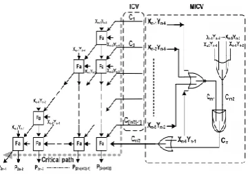
To analyze the fixed-width RPR, we design by directly injecting ICV(β) to meet the statistic distribution and one minor compensation vector MICV(α) to overcome the insufficient error compensation cases. The compensation vector ICV(β) is analyzed by directly injecting the partial terms of Xn-1Yn/2, Xn-2Y(n/2)+1, Xn-3Y(n/2)+2, . . . , X(n/2)+2Yn-2.
These directly injecting compensation terms are labelled as C1, C2, C3, . . ., C(n/2)-1 in Fig. 9. The other compensation vector used to overcome the insufficient error compensation case is designed by one conditional controlled OR gate. One input of OR gate is injected by X(n/2) Yn-1, which is used to realize the function of compensation vector
β.
The other input is conditional controlled by using formula to judge whether β = 0 and βl = 0. The final function is analysed by one NOR gate, while its inputs are Xn-1Yn/2, Xn -2Y(n/2) +1, Xn-3Y(n/2) +2, . . ., X(n/2)+2Yn-2. If both of these two outputs are true, a compensation term Cm is generated via a two-input AND gate. Then, Cm is given together with X(n/2) Yn-1 into a two-input OR gate to correct insufficient error compensation. For the case of β = 0 and βl = 0, one additional carry-in signal C(n/2) is given into the compensation vector to modify the compensation value as β + 1 instead of β. Moreover, the carry-in signal C(n/2) is given in the bottom of error compensation vector, which is the farthest position from the critical path.
Hence, the error compensation precision in the fixed-width RPR can be improved, the computation delay is not postponed because the critical supply voltage is governed by the critical delay time of the RPR circuit, preserving the critical path of RPR
© 2017, IRJET | Impact Factor value: 5.181 | ISO 9001:2008 Certified Journal | Page 940
Fig. 9. Proposed high-accuracy fixed-width RPR multiplierwith compensation constructed by the multiple truncation EC vectors combined ICV together with MICV.
IV. PERFORMANCE COMPARISONS
To evaluate and compare the performance of the proposed fixed-width RPR based ANT design and the previous fullwidth RPR-based ANT design, we implemented these two ANT designs in a 12-bit by 12-bit multiplier. The main performance indexes are the precision of RPR blocks, the silicon area of RPR blocks, the critical computation delay of RPR blocks, the error probability of RPR blocks under VOS, and the lowest reliable operating supply voltage under VOS.
Through quantitative analysis of experimental data, we can demonstrate that our proposed design can more effectively restrain the soft noise interference resulting from postponed computation delay under VOS when the circuit operates with a very low-voltage supply. Moreover, hardware overhead and power consumption can also be lowered in the proposed fixed-width RPR-based ANT design. Finally, we implemented our proposed 12-bit by 12-bit fixed-width RPR-based ANT multiplier design in TSMC 90-nm CMOS process technology. First, we compare the proposed fixed-width multiplier with other literature designs [2], [17], respectively. All performance comparisons are evaluated under 12-bit ANT-based multiplier designs.
[image:4.595.71.253.107.234.2]The precision analysis results of various fixed-width RPR multipliers or full-width RPR multiplier are shown in Table II. The fixed-width RPR multipliers are the six-bit multipliers while their LSPs are truncated and various error compensation vectors are applied. The full-width RPR multiplier is the six-bit by six-bit multiplier. As shown in Table II, the fixed-width RPR designs usually perform with higher truncation errors than that of the full-width RPR design because more computation cells are truncated. However, with appreciate error compensation vector or multiple truncation error compensation vectors, the fixed-width RPR designs still have the chance to perform with lower truncation errors.
As shown in Table II, the absolute mean error, the mean square error, the maximum error, and the variance of error in our proposed fixed-width RPR multiplier can be lowered to 21.39%, 5.57%, 9.18%, and 9.00%, respectively, in the 12-bit by 12-bit ANT multiplier design. All these truncation error evaluation indexes are the lowest ones as compared with the state-art-designs of [2] and [17] because multiple truncation EC vectors combined ICV together with MICV are applied to lower the truncation errors based on probability and statistics analysis.
TABLE II
COMPARISONS OF THE ABSOLUTE MEAN ERROR,
THE MEAN-SQUARE ERROR, AND THE VARIANCE
OF ERROR UNDER VARIOUS RPR-BASED 12-BIT
ANT MULTIPLIER DESIGN
V.SIMULATION RESULTS
The simulation results for a 12-bit multiplier is shown in below figure with inputs a = 011110110011,
b = 110110101010 and outputs c = 011010010011001111011110.
The simulation results for a Replica Pro is shown in below figure with inputs a = 001110, b = 111111 and
[image:4.595.319.534.328.415.2] [image:4.595.321.559.687.782.2]© 2017, IRJET | Impact Factor value: 5.181 | ISO 9001:2008 Certified Journal | Page 941
The simulation results for a ReProMul is shown in belowfigure with Inputs a = 111001111000,
b = 100010100101 and outputs p = 011111010001001101011000, and
Error = 000000000000000001001101.
The above result is for error compensation cicuit in repromultiplier to eliminate errors.
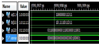
The result of topmodule for the multiplier with its error detection is shown in below figure with inputs
a = 100000011011, b = 1011110101011 and outputs p = 011000000001100000011001,
Error = 000000000000000000100001
VI. CONCLUSION & FUTURE SCOPE
In this paper, we conclude that fixed width multiplier is designed with proposed error compensation function. Error compensation circuit uses outer partial products of Baugh Wooley array multiplier to generate correction value. The proposed error compensation mainly reduces mean square error of unsigned number multiplication. The proposed fixed-width multiplier performs with lower compensation error, with lower hardware complexity, especially as multiplier input bits increase. Hence the proposed method is simulated by using Xilinx vivado 2016.1. Future possibilities may include error compensation circuit to reduce maximum and mean error of fixed width multiplication of signed numbers.
As there are two existed systems namely RELIABLE LOW-POWER MULTIPLIER USING FULL-WIDTH RPR and FIXED-WIDTH RPR is capable of operating multiplier through the binary adders. In order to overcome the drawback of full-width RPR in parameters like power consumption and area over-head up to some extent we are
going for second existed system. In this, we performed a 12*12-bit multiplier and we can also extend our project to 16*16-bit multiplier and so on.
VII.REFERENCES
1) (2009). The International Technology Roadmap for Semiconductors [Online]. Available: http://public.itrs.net/
2) B. Shim, S. Sridhara, and N. R. Shanbhag, “Reliable low-power digital signal processing via reduced precision redundancy,” IEEE Trans. Very Large Scale Integr. (VLSI) Syst., vol. 12, no. 5, pp. 497–510, May 2004.
3) B. Shim and N. R. Shanbhag, “Energy-efficient soft-error tolerant digital signal processing,” IEEE Trans. Very Large Scale Integr. (VLSI) Syst., vol. 14, no. 4, pp. 336–348, Apr. 2006.
4) R. Hedge and N. R. Shanbhag, “Energy-efficient signal processing via algorithmic noise-tolerance,” in Proc. IEEE Int. Symp. Low Power Electron. Des., Aug. 1999, pp. 30–35.
5)V. Gupta, D. Mohapatra, A. Raghunathan, and K. Roy, “Low-power digital signal processing using approximate adders,” IEEE Trans. Comput. Added Des. Integr. Circuits Syst., vol. 32, no. 1, pp. 124–137, Jan. 2013.
6) Y. Liu, T. Zhang, and K. K. Parhi, “Computation error analysis in digital signal processing systems with over scaled supply voltage,” IEEE Trans. Very Large Scale Integr. (VLSI) Syst., vol. 18, no. 4, pp. 517–526, Apr. 2010.
7) J. N. Chen, J. H. Hu, and S. Y. Li, “Low power digital signal processing scheme via stochastic logic protection,” in Proc. IEEE Int. Symp. Circuits Syst., May 2012, pp. 3077–3080.
8) J. N. Chen and J. H. Hu, “Energy-efficient digital signal processing via voltage-over scaling-based residue number system,” IEEE Trans. Very Large Scale Integr. (VLSI) Syst., vol. 21, no. 7, pp. 1322–1332, Jul. 2013.
9) P. N. Whatmough, S. Das, D. M. Bull, and I. Darwazeh, “Circuit-level timing error tolerance for low-power DSP filters and transforms,” IEEE Trans. Very Large Scale Integr. (VLSI) Syst., vol. 21, no. 6, pp. 12–18, Feb. 2012.
© 2017, IRJET | Impact Factor value: 5.181 | ISO 9001:2008 Certified Journal | Page 942
11) Y. Pu, J. P. de Gyvez, H. Corporaal, and Y. Ha, “An ultralow energy/frame multi-standard JPEG co-processor in 65-nm CMOS with sub/near threshold power supply,” IEEE J. Solid State Circuits, vol. 45, no. 3, pp. 668–680, Mar. 2010.
12)H. Fuketa, K. Hirairi, T. Yasufuku, M. Takamiya, M. Nomura, H. Shinohara, et al., “12.7-times energy efficiency increase of 16-bit integer unit by power supply voltage (VDD) scaling from 1.2V to 310mV enabled by contention-less flip-flops (CLFF) and separated VDD between flip-flops and combinational logics,” in Proc. ISLPED, Fukuoka, Japan, Aug. 2011, pp. 163–168.
13) Y. C. Lim, “Single-precision multiplier with reduced circuit complexity for signal processing applications,” IEEE Trans. Comput., vol. 41, no. 10, pp. 1333–1336, Oct. 1992.
14) M. J. Schulte and E. E. Swartzlander, “Truncated multiplication with correction constant,” in Proc. Workshop VLSI Signal Process., vol. 6. 1993, pp. 388–396.
15) S. S. Kidambi, F. El-Guibaly, and A. Antoniou, “Area-efficient multipliers for digital signal processing applications,” IEEE Trans. Circuits Syst. II, Exp. Briefs, vol. 43, no. 2, pp. 90–95, Feb. 1996.
16)J. M. Jou, S. R. Kuang, and R. D. Chen, “Design of low-error fixed-width multipliers for DSP applications,” IEEE Trans. Circuits Syst., vol. 46, no. 6, pp. 836–842, Jun. 1999.
17) S. J. Jou and H. H. Wang, “Fixed-width multiplier for DSP application,” in Proc. IEEE Int. Symp. Comput. Des., Sep. 2000, pp. 318–322.
18) F. Curticapean and J. Niittylahti, “A hardware efficient direct digital frequency synthesizer,” in Proc. 8th IEEE Int. Conf. Electron., Circuits, Syst., vol. 1. Sep. 2001, pp. 51–54.
19) A. G. M. Strollo, N. Petra, and D. D. Caro, “Dual-tree error compensation for high performance fixed-width multipliers,” IEEE Trans. Circuits Syst. II, Exp. Briefs, vol. 52, no. 8, pp. 501–507, Aug. 2005.