REFERENCE MANUAL
DISK BASED
OPERATING SYSTEM
GENERAL AUTOMA TION, INC.
I I""" I I I ,'II '
@
GENERAL AUTOMATION, INC. _ _ _ _ _ _ _ _ _ _ _ _ _PRICE $10.00
~~88A00142A-B
REFERENCE MANUAL
GA18/30
D-ISK
BASED
OPERATING SYSTEM
Technical Notice No. 1 Installed
GENERAL AUTOMATION, INC.
Automation Products Division
1055 East Street, Anaheim, California 92805 (714) 778-4800
~~L~~~~
_ _-88A00142A-B
REVISION
Symbol Description Approved Date
A Programming Release
~~L~~~~
_ _---8-8-A-O-O-1-4~~-i;-~
Section
1
2
Revised Dec 70
CONTENTS
Title
INTRODUCTION
1.1 General
DBOS PROCESSING
2. 1 General Information
2. 2 Control Command Input
2.2. 1 Control Command Input from the Teletype Keyboard
2.2.2 Control Commands Input from Cards
2. 3 Control Command Listing
2. 4 Sy stem Control Command and Commentary
2.4. 1 Logical Unit Assignment
2.4.2 Job Command
2.4.3 Copy Command 2. 4 . 4 Replace Command
2.4. 5 Delete Command
2.4.6 List Directory Command
2.4. 7 Pack Directoried File Com~ard
2.4. 8 Dump Command ,I;:
2.4.9 PDump Command
2.4. 10 Program Execution Command
2.4~ 11 Processor Execution
2.4. 12 Write End-of-Data Image ($EOD)
2.4. 13 Paper Tape Segment Routine ($PREEL)
2. 5 Predefined DBOS Processors
2.5. 1 Symbolic Assembler 2. 5. 2 Fortran Compiler
2 • 5.3 Core Image Converter
2.5.4 Source Image Editor 2. 5. 5 Debug Program
2. 5. 6 Sequence/Compare Program
2.5. 7 System Generation Utility 2. 5. 8 Bootstrap Loader
2.5.9 Paper Tape Visual Header Generator
2.6 DBOS Processing Examples
2. 7 Media Data Record Formats
2 . 7 • 1 Card Data
2.7.2 Paper Tape Formats
2.7.3 Disk Formats
Page 1.1-1 1.1-1 2.1-1 2.1-1 2.1-1 2.2. 1-1 2.2.2-1 2.3-1 2.4-1 2.4.1-1 2.4.2-1 2, 4 3-1
':-.~1( . ~ , •. ~.":' •
~~L~~n~~
_ _ _ _
-88A00142A
CONTENTS (continued)
Section Title Page
2.8 Establishing New Files 2.8-1
2.8.1 Reas signing Files 2.8.1-1 2.9 JOB Control from Directoried Disk File 2.9-1
3 DBOS OPERATIONS 3.1-1
3.1 DBOS Operations 3.1-1
3.1.1 Bootstrap Loading from Disk 3.1.1-1 '3. 1 .2 Console Interrupt to the Monitor 3.1.2-1
3. 1. 3 Programmed Return to Monitor 3.1.3-1
3.1.4 Program Restart Through the Monitor 3.1.4-1 3.1. 5 Manual Entry to the Monitor 3.1.5-1
3. 1 .6 Monitor Fixed Locations 3.1.6-1
1.2 Executi ve Operations 3.2-1
3.3 System Messages 3.3-1
3.3. 1 Input/Output Error Messages 3.3.1-1
3.3.2 Control Command Error Messages 3.3.2-1
3.3.'3 Prace s sing Error s 3.3.3-1
4 SYSTEM GENERATION 4. 1-1
4. 1 Introduction 4. 1-1
4.2 Console Bootstrap Procedure 4.2-1
4.3 Bootstrap Program Execution 4.3-1
4.4 System Generator Execution 4.4-1
4.4. 1 Store Monitor 4.4 1
4.4.2 Store Executive 4.4-1
4.4.3 DBOS Characteristic Definition 4.4-2 4.4.4 Store Monitor and Execute 4.4-2
4.5 Completlon of the System Generation 4. 5-1
4.6 Card Controlled System Generation 4.6-1
4.7 Paper Tape Systems 4.7-1
4.7. 1 Console Bootstrap Procedure 4.7-2 4.8 Bootstrap Program Execution 4.8-1/2
4.9 System Generator Execution 4.9-1/2
4.10 Loading the Executive Tape 4.10-1/2
4.11 DBOS Characteristics Definition 4.11-1/2
4.12 Store Monitor and Execute 4.12-1/2
4.13 Completion of System Generation 4.13-1/2
4.14 DBOS Configuration Kit 4.14-1
~~L~~~~
_ _ _ _ _ _ _ _ _ _ _ _ _ _ _ _ _ _ _ _~
88A00142A
CONTENTS (continued)
Section Title Page
5 LOGICAL INPUT/OUTPUT SYSTEM 5.1-1
5.1 General Information 5.1-1
5.2 LIO Calling Sequences 5.2-1
5.2. 1 Input/Output Request 5.2.1-1 5.2.2 I/O Request Status Check 5.2.2-1
5.3 LIO Usage 5.3-1
5.3. 1 Logical Disk Driver 5.3.1-1 5.3.2 Logical Disk Packing Driver 5.3.2-1 5.3.3 Logical Card Driver 5.3.3-1 5.3.4 Logical Line Printer Driver 5.3.4-1 5.3.5 Logical Teletype Driver 5.3.5-1 5.3.6 Logical Paper Tape Driver 5.3.6-1
6 DESCRIPTION OF I/O SUBROUTINES 6.1-1
6. 1 General 6.1.1-1
6. 1. 1 I/O Driver Organization 6.1.1-1
6.2 Basic Calling Sequence 6.2-1
6.2. 1 N arne Parameter 6.2.1-1
6.2.2 I/O List Parameters 6.2.2-1 6.3 General Format of I/O Calls 6.3-1
6.3.1 Calling Sequences 6.3-1
6.4 Bulk Storage Subroutine (BULKN) 6.4-1 Appendix
A DISK SECTOR MAP A-I
B STANDARD CHARACTER CODES B-1
C EBCDIC DECIMAL EQUIVALENCE C-l
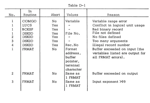
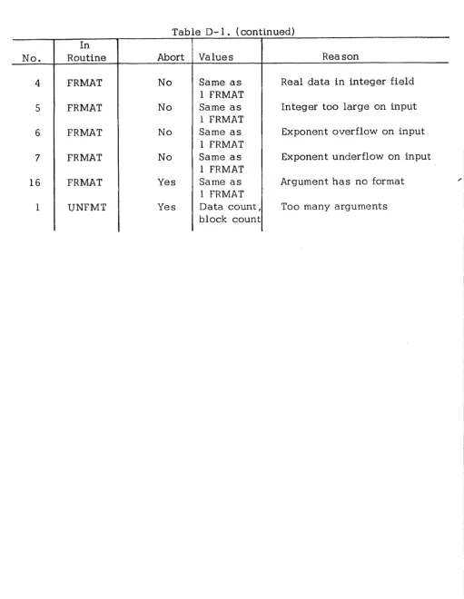
D FORTRAN EXECUTION (RUNTIME) ERRORS D-l
E FORTRAN COMPIlATION ERRORS E-1
F DBOS LOGICAL UNIT ASSIGNMENTS F-1
G DBOS FILE NAMES AND DESCRIPTION TABLES G-1
~~L~~~~
_ _ _ _ _ _ _ _ _ _ _ _ _ _ _ _ _ _ _ _ _ _~
88A00142A
1.1 GENERAL
SECTION 1 INTRODUCTION
The GA 18/30 Disk Based Operating System (DBOS) is a comprehensive, user-oriented operating system which provides the User with the following features:
a. System Operation.
Provides efficient operations under monitor control. Simplifies manual operations.
Reduces operator errors and job set-up time. Provides simplified control sequences.
Allows efficient file control. b. Job Processing.
Initiates assemblies, compilation, program check out and execution. Assigns files and peripheral equipment.
Allocates memory.
Provides batch-processing of jobs. c. Input/Output System
I/O drivers.
I/O interrupt control.
Data packing and unpacking.
Device independent 101 ica 1 I/O units and devices.
~~L~~~~
_ _ - _ _ _ _ _ _ _ _ _ _ _ _ _ _ _ _ _ _ _~
88A00142Ad. Standard Processor Master Files.
Symbolic assembler.
FORTRAN
Core image converter (loading and linking program) .
Source language editor.
Debug routine.
e. Programmer/Operator Aids
Program execution by program name.
Diagnostic error mes sages.
Simplified calling sequences.
Memory dump.
Directoried files.
f. Sy stem Preparation and Maintenance.
Simplified system generation.
Replacement and deletion of directoried files.
Listed output of file directories.
User program in directoried files.
DBOS a llows job proces sing to proceed under the direction of control commands.
Control commands may be submitted by the programmer or prepared by the
operator and input to the system from the teletype keyboard I card reader I or
paper tape reader. Jobs may be batched or singly processed under guidance by
the operator.
~~L~~~~
_ _ _ _ _ _ _ _ _ _ _ _ _ _ _ _ _ _ _ _ _ _ _~
88A00142A
DBOS operates in the following minimum hardware configuration:
a. A GA 18/30 Industria 1 Supervisory System Computer with 8192 word s of core memory.
b. 1 Model 1362 or 1363 teletype unit. c. 1 Model 1341 or 1344 Disk storage unit.
The addition of the following peripherals enhances the utility of DBOS: a. Model 1311 card reader.
b. Model 1313 card punch. c. Model 1352 line printer.
d. Model 1321 paper tape reader. e. Model 1322 paper tape punch.
DB OS generation requires high speed paper tape or card input. This manual is intended as a general reference manual to be used by both programmers and operators. It provides descriptions of DBOS proces sing functions I including
control command configurations I and standard processor usage; system
operations I including bootstrapping I system entry methods I end system
messages; system generation methods and techniques; and usage of the input/ output system.
~~L~~~~
_ _ _ _ _ _ _ _ _ _ _ _ _ _ _ _ _ _ _ _ _ _ _ 88A00142A2. 1 GENERAL INFORMATION
SECTION 2 DBOS PROCESSING
The GA 18/30 Disk Based Operating System (DBOS) provides complete proces.sing capabilities in the following areas:
a. As sembly and compilation of source language programs. b. Loading and execution of user programs.
c. Maintenance of user and system programs on disk storage. d. Device independent input/output operations.
e. Sequential job processing from control commands.
DBOS consists of the following components:
1. The Monitor.
The monitor is a core resident program which processes internal interrupts I loads system processors from disk, processes
user-programmed returns to DBOS I and contains system-wide parameters.
2. The Logical I/O System.
The logical I/O system is a core resident set of input/output drivers, I/O device tables I and a central control routine for
performing operation s according to logical device specifications.
~~L~~~~
_ _ _ _ _ _ _ _ _ _ _ _ _ _ _ _ _ _ _ _ _ _ _~
88A00142A
3. The Executive.
The executive is a system processor which is loaded by the
monitor to proces s control commands. The control commands define
logical unit assignments, program assembly or compilation, program
execution, and disk utility functions.
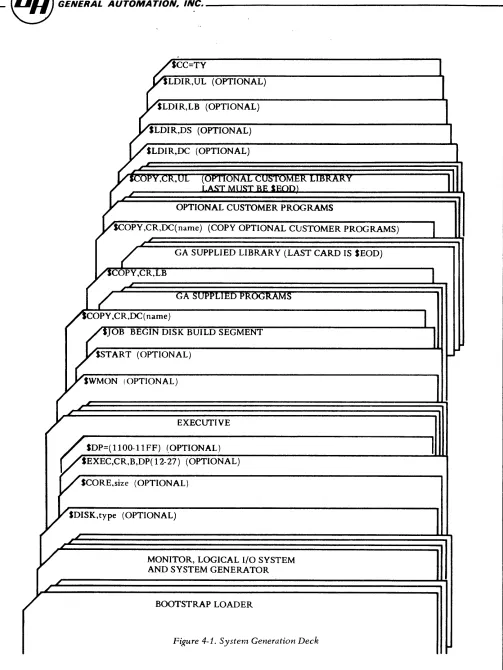
DBOS is initially created by a system generation process. This process is
described in section 4 of this manual. During system generation, the system
is written onto disk and , when it is to be activated, is read into core via
a disk IPL operation (see section 3, DBOS Operation).
~~L~~~~
_ _ _ _ _ _ _ _ _ _ _ _ _ _ _ _ _ _ _ _ _ _ _88A00142A
2.2 CONTROL COMMAND INPUT
The DBOS user communicates processing requests to the system by means of control commands. Control commands are read by the system and input to an
80-character storage buffer for processing.
These commands ha ve the following syntactical format:
where:
$
command
~PtiO~
$command [, oPtion] 6comments
is the control command identification character and is always
the first character of the control command input record.
represents one of the legal command syntax structures.
represents an optional command modifier. All data within
braces is optional including delimiters.
indicates a blank character. This blank acts as the command
terminator. Only comments may follow.
comments represents an optional string of characters from the GA 18/30
character set and arc included for annotation purposes. Comments
are listed on the system log but have no processing function.
~~L~~~~
_ _ _ _ _ _ _ _ _ _ _ _ _ _ _ _ _ _ _ _ _ _~
88A00142A
Control commands are input from the system I s logical unit CC. The teletype
keyboard is the standard device assigned to logical unit CC. The most
meaningful alternate CC device is the card reader since this provides
batch-processing capability to the system.
~~L~~~~
_ _---~
88A00142A
2.2. 1 CONTROL COMMAND INPUT FROM THE TELETYPE KEYBOARD
When logical unit CC has its standard device assignment (teletype keyboard) I
DBOS indicates the start of a new control command sequence with the message
DBOS CC
This signifies that subsequent control commands are to be keyed-in by the
operator. The system processes these commands as follows:
1. The system signals its readiness to receive a control command
by output of a control command request which consists of a Line
Feed I a Return I a ? and a space. Only following this request can
the operator key-in a control command.
2. The operator may key-in a control command of up to 80 characters I
including comments. Keyed-in control commands are terminated
by striking the RETURN key on the keyboard (no trailing blank is
required). Proces sing begins immediately following the RETURN key.
If comments are included I a blank (space) must appear before the
comment string.
~~L~~~~
_ _ _ _ _ _ _ _ _ _ _ _ _ _ _ _ _ _ _ _ _ _ _88A00142A
2.2.1-2
3. Key- in errors may be deleted, if detected prior to the RETURN key I
in either of two ways:
a) By striking the RUB-OUT key on the keyboard, the operator deletes the entire command. Upon receipt of the RUB-OUT key, the system immediately requests a control command as in 1. ,
above.
~~L~~~~
_ _ _ _ _ _ _ _ _ _ _ _ _ _ _ _ _ _ _ _ _ _~
88AQ0142A
2.2. 2 CONTROL COMMAN DS INPUT FROM CARDS
When logical unit CC is reassigned to the card reader I the system reads and
processes 80-column card image records. The $ character must be in column 1 and all characters up to the first blank constitute the control command.
Once the card reader is assigned as the CC device I it continues as the control
command input medium until CC is reassigned or the system is reinitialized.
~~L~~~~
_ _ _ _ _ _ _ _ _ _ _ _ _ _ _ _ _ _ _ _ _ _~
88A00142A
2. 3 CONTROL COMMAND LISTING
Control Commands are always listed, during processing I on the system log
(logical unit 8L). The line printer is the standard 8L device. If 8L is assigned to the teletype printer, the listing is suppressed if the CC input is from the teletype keyboard.
~~L~~~~
_ _ _ _ _ _ _ _ _ _ _ _ _ _ _ _ _ _ _ _ _ _ _88A00142A
2.4 SYSTEM CONTROL COMMAND AND COMMENTARY
The following subparagraphs define the specific control commands acceptable
to DBOS. Each must conform to the general format specified in paragraph 2. 2.
Optional elements are indicated by brackets ([ ] ). An optional element
includes all items within the braces, i. e. , [, pJ indicates that the comma and
P may be omitted. These commands define the major processing functions of
the system.
Commentary
The comment command allows additional commentary in the control command input
stream. It is of the form:
Example
STOB
Sc
SA
Revised Dec 70
SC~ commentary
Assemble real time executive
10/15/70 version 1, modification 2
Invoke assembler
~~L~~~~
_ _ _ _ _ _ _ _ _ _ _ _ _ _ _ _ _ _ _ _ _ _~
88A00142A
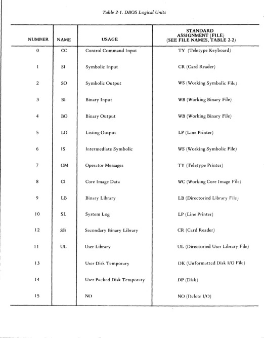
2.4. 1 LOGICAL UNIT ASSIGNMENT
Each DBOS system is generated with standard logical unit assignments to
conform to the particular hardware configuration. This includes User disk sector
allocation. Table 2-1 defines the generated standard assignments. Logical
units may be referred to symbolically or by number (0-15).
A logical unit assignment command is provided which can override the generated
standard as signments. This override can be defined to continue for the duration
of only one JOB or through multiple JOBS. A JOB duration is defined as the
period between the occurrence of a SJOB command and a subseqte nt SJOB
command. Programs which use the Logi cal I/O system for input/output
may, through use of this command, use any devices. This command assigns
one of the logical units shown in table 2-1 to one of the files shown in
table 2-2. It has the following format:
where:
$lun=file [<name)
l
C
pJ
L
(bS-es>jlun represents one of the logical unit names or valid decimal
numbers shown in table 2-1.
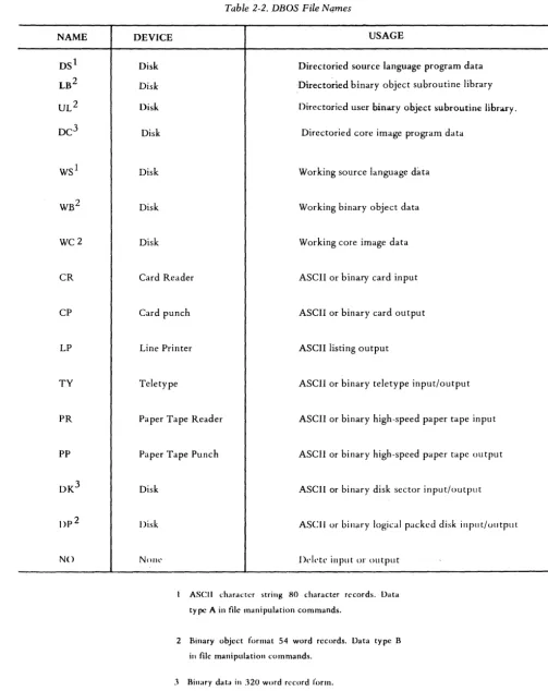
file is the name of the device (CR, PR) or II file II (DS I
we)
asshown in table 2-2 I to which the logical unit is being assigned.
[image:25.621.55.560.10.779.2]~~L~~~~
_ _ _ _ _ _ _ _ _ _ _ _ _ _ _ _ _ _ _ _ _ _ _ _ 88A00142A(name)
(bs-es)
p
represents a program name if II file" is a directoried file
(DS, LB, DC or UL). If (name) is used, the logical unit assignment is to that program within the specified file. represents a disk storage area. "bs II defines the beginning
sector address (in hexadecimal) and "es" defines the ending sector address (in hexadecimal). If this option is used I the
logical unit assignment is to that area of disk.
specifies that a LUN assignment is to be maintained through successive JOBS. Logical units defined with the P option will be overridden by an IP L operation. When the P option is omitted the LUN assignment will be maintained for one JOB sequence only. The next $JOB will reset the LUN assignments to the last user specified LUNs tagged with the "P" option. LUNs not specifically specified by the user will be reset to the generated system standard.
Examples:
1. $LO=TY
·The teletype printer is aSSigned as the listing output device.
2. $CC=CR
The card reader is assigned as the control command device.
~~L~~~~
_ _ _ _ _ _ _ _ _ _ _ _ _ _ _ _ _ _ _ _ _ _~
88A00142A
3. $SI=WS
The working source language data file (WS) is assigned to symbolic input; i. e. I subsequent symbolic input will be taken from the WS file
on disk. 4. $SI=DS (USRI)
The symbolic input logical unit is assigned as program USRI which is in the directoried source file (DS).
Note: Caution must be exercised when ass.i.gning non-standard devices to OM I CC and SL. For example; assignment of the
line printer to OM to list FORTRAN error messages is inadvisable. FORTRAN expects to receive input from device OM which is
not possible from a line printer. Caution should always be exercised not to assign output only devices as input files and vice versa.
~~L~~~~
_ _ _ _ _ _ _ _ _ _ _ _ _ _ _ _ _ _ _ _ _ _~
88A00142A
2.4.2 JOB COMMAND
The JOB command sets the logical unit assignments to the generated standards
(table 2. 1) or to the last user specified assignments tagged with the ., P" option.
(see 2.4. 1) In addition the JOB command initializes (opens) disk files. This
command may be used at any time, but it normally is the first command in a job
stack.
The format is:
SJOB
~~L~~~~
_ _ _ _ _ _ _ _ _ _ _ _ _ _ _ _ _ _ _ _ _ _~
88A00142A
2.4. 3 COpy COMMAND
The COpy command provides file-to-file copying capability. It also provides a method for defining names of programs in directoried files (DS, LB, UL and DC file s) .
The format of the COpy command is:
A
[ (name)
J
A
~name)
]B B
$COPY , file
l (bs-es) ~ , file 2
(bs-es)
C C
D
,
T I D"
y ISource
.-J
DestinationWhere:
A are optional data type specifications
B A- specifies ASCII data in 80 character record form.
C
o
B- specifics bin ary data in 54 word assembler object or core image record form.
~~,~LAU~~~
_ _ _ _ _ _ _ _ _ _ _ _ _ _ _ _ _ _ _ _ _ _ _~
88A00142A
C- specifies unchecksummed binary data in 60 word
record form
D- specifies binary data in 320 word record form on disk.
, file 1 represents the input (source) file involved in the COpy
represents the output (destination) file involved in the COpy
[
(name)
J
(bs-es)represent options, and (name) and (bs-es) have the same meaning as defined in subparagraph 2.4. 1.
When the COPY command is processed, data is copied from filel to file2 until an ASCII END I binary end (OFOO) record I end -of-data ($EO D), or end-of-file
is encountered. An ASCII END may exist as the first or second field of a source record. Therefore a label may appear before the END record in an I
assembler source filel' i. e. I NAME END. NOTE: The END statement may
not begin in columns 1 or 21.
If A, B, C or 0 is not specified, the data type is determined from the file
name. Disk files are assumed to be 320 word binary records. If the file is capable of maintaining both ASCII and binary data, ASCII is taken as the normal type.
The DBOS system maintains implicit definitions for all files, whether disk resident or external devices. The optional typo specification overrides thoso' .lmplicH dcfin.lUons, L e., SCOPY, CI{,A In this example the .implicit definHion of type binary for file LB is overriden and forced to be ASCII. Such action, while permis sible, will create improper structure of the file for the
~~L~~~~
_ _ _ _ _ _ _ _ _ _ _ _ _ _ _ _ _ _ _ _ _ _~
88A00142Ainserted program (LB may contain only type "B" data). The user should only specify a type code when:
1. The destination file is of a "type" different from the input file "type". 2. An external file of unchecksummed binary data is to be copied, type "CII
•
3. Both files are capable of containing ASCII and binary data and type "binary" is required. Note: the default type for such files is.
ASCII. (Le., CR, CP)
~~L~~n~~
_ _ _ _ _ _ _ _ _ _ _ _ _ _ _ _ _ _ _ _ _ _ _ 88A00142ALIBRARY EXPANSION
When a program is copied to a directoried library file (LB or UL) I the program
name(s) is taken from the input program. Multiple programs may be input to create or append a library. The input must be terminated with an end of data ($EOD) record. (See section 2.4. 12 for use of $EOD.)
~~L~~~~
_ _ _ _ _ _ _ _ _ _ _ _ _ _ _ _ _ _ _ _ _ _ _WC AND DC INPUT
Core image data are absolute programs with subroutines properly linked and all external references satisfied. In order for programs to be in core image format, they must have been processed by the core image converter (see subparagraph
2.5.3) which loads binary object programs, links program elements and per-forms proper relocation adjustments, or the assembled binary object from an absolute assembly. No external references may be used in assembly. Precede SA with SBO=WC to create object in WC file.
Once a program is in core image format, it can be loaded from the DC or
we
file and executed without further processing. 'See paragraphs 2.4.20 and 2.4.11).
SCOpy Examples:
1. SCOPY, DS (PROGA), WS
Copy PROGA from the DS file to the WS file. ASCII 80 character record form is used.
2. SCOPY, B, CR, LB SEOD
Copy a binary file from the card reader to the 18 file. The binary file is identified in the L8 directory according to the name contained on the input program data records. (B specification is redundant but permissible. )
The last copy operation affecting a library must be followed by a SE0D.
~~L~~~~
_ _ _ _ _ _ _ _ _ _ _ _ _ _ _ _ _ _ _ _ _~
" 88A00142A
2.4.3-6
3. SCOpY, WC , DC(PROGX)
Copy the working core image file (WC) into the directoried core image program data file and give the program the name PROGX in the DC directory.
4. SCOPY, DS(PROGS) I LP
Copy program PROGS from the DS file to the line printer (LP) •
S. SCOPY, DC(NAME),B, TY
~~L~~~~
_ _ _ _ _ _ _ _ _ _ _ _ _ _ _ _ _ _ _ _ _ _~
88A00142A
2.4.4 REPLACE COMMAND
The REPLACE command provides the capability to replace a previously named program in a directoried file with data from another file.
The format of the REPLACE command is:
where: , file
l
(name)
IA , B
,C
,D
$REPLACE , file 1 (name) (bs-es)
If
destination A
I B I file2
C D \"
I(name)
l
L(bs-es~
source
represents the output file, i. e. I the file which will receive
the replacement program.
repre sents the name of the program in file 1 which is being replaced. The name will be assigned to the new program unless file I is a library file. In this case the program name will be
taken from the input data.
are optional data type specifications, as defined in subparagraph
2.4.3.
represents the input file; i. e. I the file from which the
replace-ment program is to be copied.
~~L~~~~
_ _ _ _ _ _ _ _ _ _ _ _ _ _ _ _ _ _ _ _ _ _88A00142A
(name) are optional and have the same meanings as defined in (bs-es) subparagraph 2.4. 1 .
$REPLACE examples:
2.4.4-2
1. $REPLACE I DC(PROG7), WC
Replace PROG 7 in the DC file with the program in the WC file. 2. $REPLACE, LB(SUBA) ,CR
$EOD SPACK
Program SUBA of the LB file is replaced by the binary record in the CR file. The last REPLACE operation affecting a library file must be followed by a $EOD and $PACK.
3. $REPLACE, DS(PROG23) ,A, WS
Program PROG23 of the DS file is replaced by the symbolic program
in the WS file.
NOTE
The REPLACE command does not write the new program over the program being replaced. Rather I the new program
is written in the first unused space of the file and the nbs II
and II es II addresses in the directory are altered to reflect
the replacement. A subsequent $LDIR command would indicate the area occupied by the replaced program as
******
unless a SPACK command has compressed thefile. See $LDIR (2.4. 6) and SPACK (2. 4. 7). After
~~L~~~~
_ _ _ _ _ _ _ _ _ _ _ _ _ _ _ _ _ _ _ _ _ _~
88A00142A
2.4. 5 DELETE COMMAND
The DELETE command is used to delete an existing named program from a directoried file.
The format of the DELETE command is:
where:
, file
(name)
Example:
$DELETE, file (name)
represents the name of one of the directoried files (DS, LB, UL or DC)
represents the name of the program which is to be deleted.
$DELETE, LB (SUBA) SPACK
The program named SUBA is deleted from the LB file. Note: A SPACK command must be executed after deleting subroutines from the library. See 2.4. 7 .
~~L~~~~
_ _---~
88A00142A
2.4. 6 LIST DIRECTORY COMMAND
The list directory command causes the current status of a directoried file to be listed on the SL (system log) unit.
The command format is:
$LDIR. file
~s-e~
where It file" is the name of the directoried file whose directory is to be listed.
The LDIR listing has the format:
bs es type rpr ipr name
for each item in the directory. "bs" specifies the beginning sector address (in hexadecirna 1) I and" es II the ending sector address (in hexadecimal), of the
disk area assigned to the storage of program "name". For library subroutines type indicates the program type as
LIB Called by LIBF ENT Called by CALL
~~L~~~~
_ _---~
88A00142A"rpr" indicates the precision of real numbers and II ipr" indicates the precision
of integer numbers as
blank
SPR
EPR
Unspecified
Standard pre ci s ion
Extended precision
If an area has been deleted or replaced I the listing format is:
bs es
******
~~L~~~~
_ _ _ _ _ _ _ _ _ _ _ _ _ _ _ _ _ _ _ _ _ _ _ 88A00142A2.4.7 PACK DIRECTORIED FILE COMMAND
The pack directoried file command packs the elements in directoried files to eliminate unused sectors resulting from program deletions or replacements.
The format of the command is:
SPACK, file
where II file II is the name of one of the directoried files (DS, L8, UL or DC) .
NOTE
For proper processing of libraries (L8 or UL) by the Core Image Converter . The PACK command must be is sued following any update to the library.
~~L~~~~
_ _ _ _ _ _ _ _ _ _ _ _ _ _ _ _ _ _ _ _ _ _ _ 88A00142A2.4.8 DUMP COMMAND
The dump command produces a hexadecimal listing of a file on the 8L (system log) unit.
The command format is:
A (name)
B
$DUMP
,
I fileC
(bs-es) D
where:
I A are optional data type specifications
I B as defined in subparagraph 2.4. 3 I I C and define the data type of the file
I D data.
I file is the name of the file to be dumped
[
(name )Jare optional and have the same meanings as defined in (bs-es) subparagraph 2.4.2.
A $DUMP listed line has the format:
lac datal data 2 ... datan
~~L~~~~
_ _ _ _ _ _ _ _ _ _ _ _ _ _ _ _ _ _ _ _ _ _~
88A00142Awhere:
loc represents the relative record location (hexadecimal) of the
first data item in the first data item in the line.
datai represents a data item
n is 16 if 8L is assigned to the line printer and 8 if the 8L is
as signed to the teletype printer.
If the nth item of a line (8th or 16th item) and the next n items are identical,
the next line is not printed. When this occurs one response occurs.
Assume a block of 32 words contains a recurring series of numbers; 1, 2 I 3, 4,
5, 6, 7, 8 followed by a disimilar pattern 8, 7, 6 I 5, 4, 3, 2, 1.
The listed output would appear as two lines as follows:
examples: 2.4.8-2 LaC 1 33 Datal
, 1
8 7
$DUMP, DC(PROGA)
3 4 5 6 7
6 5 4 3 2
Data8
8
~~L~~~~
_ _---~
88A00142ADumps the program named PROGA from the DC file.
$DUMP,B,DK(lSFO-lSF5) .
Dumps the binary data from the DK file, sectors 15FO through 15F 5.
~~L~~~~
_ _ _ _ _ _ _ _ _ _ _ _ _ _ _ _ _ _ _ _ _ _ _ 88A00142A2.4. 9 PDUMP COMMAND
When the monitor assumes control of the system, core memory is saved prior
to execution of the system executive. The PDUMP command provides a selective
dump of this core memory in hexadecimal.
The command is:
where:
-Ioc2
represents the location (in hexadecimal) of the first core
memory word to be dumped.
represents the location (in hexadecimal) of the last core
memory word to be dumped.
Output resulting from PDUMP is on the 8L (system log) unit and consists of
lines in the following format:
loc datal data2 ... data
n
@.~~L~~~~
______________________
~
88A00142A
where:
loc the memory location (in hexadecimal) of the first data item in the
line. "locll is always a modulo 8 address.
data
i represent the contents of man ory location IIlocZ II through II locn II .
n is 16 if SL is as signed to the line printer and 8 if SL is a s signed to
the teletype printer.
If the nth item of a line (8th or 16th item) and the next n items are identical,
the next line is not printed. When this occurs, one upspace occurs. See
section Z. 4. 8 for listing example.
If the optional [, locI -
IOCzJ
is not present in the PDUMP command, theentire core memory is dumped.
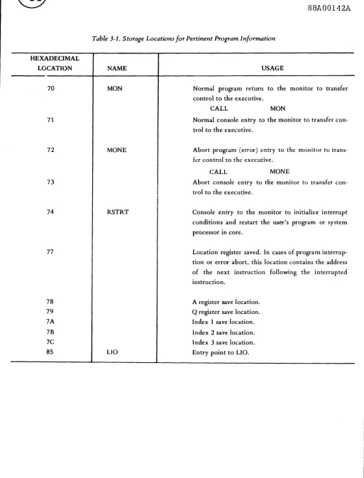
The system saves the program registers in the following locations:
REGISTER LOCATION (HEX)
I /77
A /78
Q /79
Index I /7A
Index 2 /7B
Index 3 /7C
~~L~~~~
_ _ _~
_ _ _ _ _ _ _ _ _ _ _ _ _ _ _ _ _ _~
88A00142A
examples:
1. $PDUMP, 15A5-15B3
Dumps the contents of saved core locations /15AO through /15B F .
2. $PDUMP ,70-7F
Dump the contents of saved core locations /70 through /7F which
includes the program registers.
NOTE
The monitor performs a core save function every time it is
entered by a functional program. Control may be returned
to the monitor in any of several ways:
1. Manual entry at locations /71 or /73.
2 • Programmed return via a
a. CALL MaN normal return
b. CALL MaNE error (abort) return
c. FORTRAN CALL EXIT or STOP.
d. Console interrupt.
Refer to sections 3. 1 . 2 through 3. 1 . 6.
~~L~~~~
_ _ _ _ _ _ _ _ _ _ _ _ _ _ _ _ _ _ _ _ _ _~
88A00142A2.4. 10 PROGRAM EXECUTION COMMAND
A program which is conta ined in core image format in the working core ima ge
file (WC) may be loaded and executed by use of the following command:
$LOAD [. name2 ]
where "name211 is optional and represents the name of a second program from
the DC file which is loaded along with the program from the WC file. If "name2"
is present in the command I program "name2" is executed when loading is
complete. If "name2" is not present, the program from the WC file is executed.
Only one program may be contained in the WC file at a time.
This command is similar to the Processor execution command (2.4. 11) except
that it allows loading unnamed programs.
A program may be placed in the WC file by a SCOPY operation.
~~L~~~~
_ _ - - - _88A00142A
Example:
SCOPY, WB ,WC would copy the object output from the
as sembler in file WB to the core image file WC. $COPY I
CR I
we
would copy an obj ect deck to WC for execution.The following command sequence will result in an executable program in file
WC from source media.
$IOB
$A and $F
Source Statements
$EOD $CIC
[ *MAPJ *BUILD
$LOAD Immediate execution or
SIOB
$BO=WC assembler object output to WC SA
$ LOAD immediate execution
A second program may be called into core from the
De
file along with thepro-gram from
we.
~~~~~~---~
88A00142AThe format:
$ LOAD , PROG2
where PROG2 is a program stored in the directoried file De.
The second program must be origined such that it does not overlay the program
loaded from we. (See BOUND directive under
eIe,
section 2.5.3.) (Anassem-bler ABS and ORG directive may be used to origin an assembly language program.)
A typical use for the double program call is in debugging. The command
$LOAD,D
will load the program from we and the DBOS debug routine from De.
Exe-cution will begin with debug (see section 2. 5. 5) .
Note: The debug program occupies /700 locations of high core.
(origin /7900)
~~L~~~~
_ _ - - - _ 88A00142A2.4. 11 PROCESSOR EXECUTION
Any program may be specified as a processor by having that program stored in
the directoried core image file (DC) with its name in the DC directory. A number of predefined processors are included in DBOS. These are defined in paragraph 2. 5.
A user may add his programs (processor) to the DC file by use of the copy
command.
Examples:
SCOpy I CR I DC(NAMEX)
SCOPY, WC ,DC(PROGl)
Copy an external program into DC
from cards.
Copy the unnamed program in WC into the DC file and call it PROGl .
Programs which are in the DC file may be loaded and executed by use of the following control command:
~~L~~~~
_ _ _~
_ _ _ _ _ _ _ _ _ _ _ _ _ _ _ _ _ _~
88A00142A
where:
name represents the name of the program (processor) to be loaded.
1
[,name~ is optional and represents the name of a second program from
the DC file which is also to be loaded.
If Iname2" is specified both programs are loaded into core memory and program
Iname2" is executed.
Normally I " name II is a debug program.
2
Example:
1. $PRGI5
Load and execute program PRG 15.
2. $PRGI5,D
Load both program PRG 15 and D (the debug program) and execute
the debug program. See section 2. 4. 10 for examples and origin
re strictions •
~~L~~~~
_ _ _ _ _ _ _ _ _ _ _ _ _ _ _ _ _ _ _ _ _ _ 88A00142A2.4. 12 WRITE END-OF-DATA IMAGE ($EOD)
The Core Image Converter I CIC I (see section 2.5.3) will accept data from up
to four separate binary files. Each file must terminate with a $EOD image
record. This image causes the CIC to terminate access of one file and advance
to the next or if the file is LB to stop accessing completely.
The command $EOD will close a file.
Example:
$IOB
$F
$A
$EOD
Fortran mainline to file WB.
Assembler output to file WB.
Close WB file. No more data may be entered into WB.
NOTE: The $EOD command writes on logical unit BO.
The standard assignment for BO is WB.
When a library is being terminated the $EOD command writes into the library
ft Ie instead of BO.
~~L~~~~
_ _ _ _ _ _ _ _ _ _ _ _ _ _ _ _ _ _ _ _ _~
88A00142A
Example:
$JOB open files
$COPY I CR I UL(bs-es) build library starting at bs.
$EOD
$JOB
terminate UL
reset limits for UL to standard
To make use of this new library the following steps might be used.
$JOB
$F
open files
compile mainline
Source Statements
$EOD close WB file
$SB=DP(bs-es) set disk limits for new SB
$CIC
*BUILD ,SB
$JOB
$F
call core image converter
build program and include ALL data in SB in program
open files
compile mainline
Source Statements
$EOn close WB file
$UL=DP(bs-es) set disk limits for new UL
$CIC
*BUILD I UL
2.4.12-2
call can vert
build program using only those routines called by mainline
~~L~~~~
_ _ _ _ _~
_ _ _ _ _ _ _ _ _ _ _ _ _ _ _ _$TOB
$F
open files
compile mainline
Source Statements
$A
$EOD
as semble subprogram
close WB file
$SB=DP(bs-es) set disk limits for SB
$CIC call convert
*BUILD I SB I UL build program using all data from new SB and required
routines from UL.
NOTE: In all cases the standard library file, LB is used to complete build
process.
~~L~~~~
_ _ _ _ _ _ _ _ _ _ _ _ _ _ _ _ _ _ _ _ _ _~
88A00142A2.4.13 PAPER TAPE SEGMENT ROUTINE ($PREEL) ~
A large subroutine library may require a volume of bin ary tape too great to be
handled in one reel. The DBOS command I $PREEL I will punch a $REEL image
to terminate a tape segment. The user may use this command to terminate any
number of segments. See section 2. 5. 3 for use of $REEL.
~~L~~~~
_ _ _ _ _ _ _ _ _ _ _ _ _ _ _ _ _ _ _ _ _ _ _ 88A00142A2. 5 PREDEFINED DBOS PROCESSORS
During system generation (section 4) I a group of predefined DBOS processors
are copied into the directoried core image program data file (DC). These I and
other non-predefined processors I may be loaded and executed by use of the
proces sor execution control command (subparagraph 2.4. 11) .
The standard predefined processors are:
a. Symbolic assembler. b. FORTRAN compiler. c. Core image converter. d. Source image editor. e. Debug program.
Each of these processors is described in the following subparagraphs.
~~L~~~~
_ _ - - - -_ _ _ _ _ _ _ _ _ _ _ _ _~
88A00142A
2. 5. 1 SYMBOLIC ASSEMBLER
The GA 18/30 symbolic assembler is a two-pass assembler and is given the name A in the DC file. Thus I it can be loaded into core and executed by use of the
control command:
SA
The assembler uses the following logical units:
SI Source input (pas s 1 input) LO Listing output
BO Binary output
IS Intermediate storage (pass 1 output, pass 2 input)
If the SI unit is a disk file I then the IS unit should be assigned to NO to avoid
disk duplication during pass 1.
If the IS unit is assigned to NO I both passes are taken from the SI unit. Thus
if the SI unit is the card reader and IS is assigned to NO the symbolic source deck must be input twice.
~~L~~n~~
____
---~
88A00142A
2.5. 1. 1 DBOS Assembler Extensions
Refer to the 18/30 Programming Operations Manual for assembler usage data. The DBOS as sembler has been extended beyond the basic GA assembler. These extensions are enumerated in the following paragraphs.
ASCII Text (ASC) P seudo-op
The ASC pseudo-op i.s i.dentical to the EBC statement described in the GA 18/30 Programming/Operations Manual except that ASCII data strings are generated.
REF /DEF Pseudo-op
These features per llit ., progr·,m to REFerence symbols DEFi.ned in other external programs. The tern, ext~rnal 1S meant to indicate a program or storage location
not assembled with the object program. A data table separately assembled but referenced by the object program would be an example.
A DEF pseudo-op 1 s used to specify that the symbol in its variable field may be
REFerenced by an 9xt~rnal program. A DEF statement may not appear in an absolute program. All DEF's must appear at the beginning of the source fHe to which they make reference. A DEF is identical to an ENT except that the defined symbol need not bf-~ a program entry point. It is permissable to define a symbol used in the vanable held ot a DEF with an EQU statement, i. e. I
~~L~~~~
_ _ - - - -_ _ _ _ _ _ _ _ _ _~
_ _88A00142A
OUTOl DEF EQU END OUTOl/57 As sign absolute value hex 57 to symbol
OUTOl. A REF to OUTOl will result in
the value /57 in the variable field.
A maximum of 30 ENT and/or DEF symbols may be included in a single program.
REF
A REF pseudo-op specifies that the symbol in its variable field is external.
REF's may occur anywhere in a program. Symbols which are declared as external
by REF's may occur in a multiple item expression except as an operand of a
multiply (*) operator. Machine instructions which contain REFed symbols
in their variable fields must be of the two word or long format.
Conditional Assembly
A DO pseudo-op has been provided to permit a programmer to include/exclude
selected source statements.
The statement:
DO L M,N
directs the assembler to assemble the next M lines N times. The values must fall
within the range of 0 and 255. All symbols used must be previously defined. If
M I the number of lines I is greater than one I N must be zero or one. If N is
omitted I it is assumed to be one. None of the statements within the range of the
DO can be another DO.
~~L~~~~
_ _ - - - _ 88A00142AExamples:
DO L 3,1 Assemble the next 3 lines
DC 1
DC 2
DC 3
DO L 3,0 Do not assemble the next 3 lines
DC 1
DC 2
DC 3
Source Data Preparation rormat
The DBOS Assembler wlll accept source statements which originate in column
1 or 21. The remalndc~r of the statement must be punched in relative columns,
i. e., the OP code: l ' · l . j I S eIther started in column 7 or 27. A maximum of 60
columns of data is red,] and interpreted.
~~L~~~~
_ _ _ _ _ _ _ _ _ _ _ _ _ _ _ _ _ _ _ _ _ _~
88A00142A
2. 5. 2 FORTRAN COMPILER
The GA 18/30 FORTRAN compiler is given the name F in the DC file. Thus it can be loaded into core and executed by use of the control command:
$F
FORTRAN uses the following logical units:
SI Source input LO Li sting output BO Binary output
FORTRAN is a one-pass compiler and requires no intermediate storage. The FORTRAN logical unit number u in the FORTRAN I/O statements (e. g. I READ
(u I f) list) will reference DBOS logical unit u. The user may use the standard
assignment described in table 2. 1 or define his own assignments with the executi ve command.
$u=file.
The *IOCS control card has no purpose and may be omitted. The user is advised to use the standard DBOS LUN assignments. (See table 2-1) This procedure permits any system LUN reassignments to be effective for all programs
~~L~~~~
_ _---~
88A00142Aoperating under the system.
Example:
if $lun=CR
then READ(lun, f) list would cause data to be input from the card reader.
Note: The FORTRAN disk READ and WRITE operations will always use logical unit 13 which must be assigned to fHe DK (standard assignment). The
DK file is the only unpacked disk file. The disk limits for the DK file
may be preset to any area of the disk. See section 2.8. 1 .
Refer to the IBM FORTRAN IV manual for compiler usage data (C26-3715-4).
Note:
Note:
2.5.2-2
The * control cards which are u sed to specify compiler options are
not listed.
The *ONE WORD INTEGERS is the default option when not specified.
~~L~~~~
_ _ _ _ _ _ _ _ _ _ _ _ _ _ _ _ _ _ _ _ _ _ _88A00142A
2.5.2.1 DBOS FORTRAN Extensions
Introduction
General Automation supplies subroutine library extensions for each of its
executives and operating sy stems. These routines generally are supplied to
permit access to Monitor functions by the FORTRAN programmer. This section
will be updated as new routines are made available.
Array Characteristics
FORTRAN on the 18/30 stores arrays in reverse order. That is, ARFAY(l) refers
to the highest core address assigned to the array. This arrangement is contrary
to the manner in which the machine and Monitor store data. In the following
extension discussion paragraphs special characters will be used. These
char-acters are defined as:
N = length of array (number of variables)
10 = N + 1 value to be used as subscript ba se
FORTRAN Logical I/O Interface
This subroutine provides access to the logical I/O system of DBOS. The
sub-routine operates in two modes controlled by the first argument. Details of LIO
are described in Section 5. 0 •
~~L~~~~
_ _ - - - _88A00142A
Mode 1 Data Transfer and Control CALL FLIO(I, JOQ-I))
where:
FLIO= name of routine
I = control variable for LIO>O
J
= a dimensioned array. The first variable in arrayJ
must definethe length of array
J .
i. e., JOQ-I) = length in words JOQ-2 through IQ-N) = Data
This call results in a call to LIO of the type:
CALL LIO
DC (I)
DC
J
DC 0
Mode 2 Device Status Test and Return CALL FLIO(I, J)
where:
FLIO= name of routine
I = control variable for LIO and must be <0
J = a variable which will contain the device status word upon
return from FLIO.
~~L~~~~
_ _ - - - -_ _ _ _ _ _ _ _ _ _8BA00142A
This call results in a call to LIO of the type
CALL DC
STO
LIO (1)
J
The use of FLIO requires that a control variable" I" be established. This
variable can be defined in a DATA statement.
Example: READ 54 binary characters into array J from logical unit 12.
DIMENSION J( 55) DATA IRASC/Z110C/
J(55) = 54
CALL FLIO(IRASC I J( 5 5))
Example: To test status of logical unit 12 DATA ITEST/ZFOOC/
CALL FLIO( ITEST I K)
The status of logical unit 12 will be stored in variable K.
Note: A TEST operation must be performed before the next read/write call. LIO returns immediately to the user and does not wait for operation
complete.
~~L~~~~
_ _---~-~
88A00142A
FORTRAN DBOS BULKN Interface
This subroutine provides access to the bulk handling routine (BULKN) in DBOS.
CALL BULK(I,} ,K)
where:
B ULK= name of routine
I = BULKN function (use DATA statement)
J = a dimensioned array such that
J(IQ-I) = word count
}(IQ- 2) = sector addres s
}(IQ-3 through IQ-N) is data
K = variable whi.ch will contain error status on return.
BULK waits for operation complete status before returning to the user.
Refer to Section 6.4.2 for a detailed description of BULKN .
Extreme caution must be exercised when lS ing this subroutine. It is possible
to write anywhere on the disk including areas occupied by the Monitor and files.
For safety, use FLIO or DEFINE FILE which monitors file boundaries.
~~L~~~~
_ _ - - - _88A00142A
2. 5. 3 CORE IMAGE CONVERTER
The GA 18/30 Core Image Converter is given the name CIC in the DC file. Thus
it can be loaded into core and executed by use of the Control command:
SCIC
The Core Image Converter uses the following logical units to perform a core
image file build:
BI Primary binary input
SB Secondary binary input (optional)
UL User Library (optional)
LB System library
CI Binary output
IS Intermediate storage (used to temporarily store obj ect
modules from Bl and SB)
SL Load map output (optional), missing subroutines list, and
error messages
OM Operator messages
CC Control command input
~~L~~~~
_ _ _ _ _ _ _ _ _ _ _ _ _ _ _ _ _ _ _ _ _ _~
88A00142AThe Core Image Converter (CIC) performs the functions of fixing relocatable
obj ect code, linking together main programs and subroutines and producing
an absolute core image file which can then be loaded from the disk and executed
by the DBOS disk loader. All CIC core image file builds are performed by making
two pas ses. over the obj ect data. The first pas s is required to build a list of
referenced subroutines, resolve the subroutine entry addresses and obtain a
map of memory. During the second pass I the executable core image output
file is produced on logical unit CI (normally the WC file). Note that the CIC
does not load the executable program directly into memory, hence all of
avail-able memory may be allocated and used during problem program execution.
The Core Image Converter can accept object program modules from up to four
logical files. The CIC will first reference BI, which must contain the MAIN
program as itl s first object module and any number of subroutine modules.
Optionally, subroutines may be input from[s~. Both BI and SB must be terminated
by $EOD image records (use $EOD command). All subroutines included in BI
and SB are incorporated into CI whether actually referenced or not. The user may
therefore include object modules which will be used in place of standard library
routines to better satisfy his requirements even though they are not explicitly
called out from his program logic.
~~L~~~~
_ _ - - - -_ _ _ _ _ _ _ _ _ _ _ _ _ _ 88A00142AThe final two input files are subroutine libraries [ULJ (optional) and LB. Only
those subroutines actually called out in the load process will be included in CI.
The CIC will make multiple passes over a library to satisfy references. This
feature makes it unnecessary to 'level' a subroutine library. To optimize
pro-cessing time the use of leveled libraries is preferred.
CIC Control Commands:
(Items enclosed in brackets are optional.)
rMA~
.
rBOUND [.low Jfh.igh
I
common]C INSKEL commonJ]
*9 UILD
r
SB] [.U~
MAP - The optional MAP command provides a memory map of the resulting core
image file.
BOUND - The optional BOUND command provides a means to override the default
memory boundary values. These defaults are designed to maximize user core in
batch job operation. The default value for each optional field is defined below.
Any or all of these values may be specified, however all values between the
BOUND and the particular value must be specified.
Parameter Definitions
low - first location to be occupied by program.
~~L~~~~
_ _ - - - -_ _ _ _ _ _ _ _ _ _ _ _ _ _ _88A00142A
high - last available location for program.
common - highest address assigned for common data storage. Data is stored
downward toward core location zero from address common.
INSKEL common - highest addre ss as signed for INSKEL common data storage.
Data is stored downward in core toward location zero from address INSKEL commal.
Default Definitions for BOUND Parameters
If no BOUND command is specified or some fields are selectively omitted the
following rules apply for determining default values.
low - the first location following the DBOS resident monitor.
high - the last location available to DBOS (usually end of core).
common - set to same value as high. (Note: COMMON data is stored backwards
in core.)
INSKEL common - the origin of INSKEL common is defined by the expression
(COMMON - size of common). (Note: INSKEL common data is stored backwards
in core.)
BUILD - The BUILD command initiates core image conversion. It must be the last
eIe
command.[8B]
and[u~
specify optional binary inputs.BI
will always bethe first logical file and LB will be the last logical file.
~~L~~~~
_ _ - - - _88A00142A
eIe
Error MessagesError Messages
eIe
error messages are output on8L
and prefixed by two slashes (/ /). Errormessages discussed in this section always cause
eIe
to abort._~~L~~~~
_ _ _ _ _ _ _ _ _ _ _ _ _ _ _ _ _ _ _ _ _ _ _ _88A00142A
MESSAGE
II CHECKSUM ERROR
IICODE ERROR
IIPRECISION ERROR
I lEND OF FILE
IIMISSING ROUTINES
IICC ERROR
IIRANGE ERROR
MEANING AND REMEDIAE ACTION
A particular card image element within the object module is either missing, out of sequence or was not punched properly when generated. Regenerate the object module.
A card image contains a card type code not processed by the CIC. ILS and ISS subroutine header cards are not processed. Remove the object module from the core image build.
A subroutine object module input from either BI or SB has a precision code specification different from that of the MAIN program. Change the precision definition of the object module or include the correct object module.
An end-of-file was encountered on either the IS or CI file. Allocate more storage for the working fUes. (see section 2.8.1)
This message is output followed by a list of the sub-routines referenced but not included in any of the specified input files. Include the required object modules and restart the core image build.
A card image record which did not contain an asterisk in character position 1 was encountered before the BUILD directive. Include or correct CIC Control Commands.
The program being built is too large for the specified core area. The parameters specified on the BOUND statement may be changed if used.
eIC Operator Messages (for paper tape input only)
When the
eIe
encounters a $REEL record the following mes sage is output onlogical unit OM followed by a type-in request:
//REEL
? (input request)
~~L~~~~
_ _ _ _ _ _ _ _ _ _ _ _ _ _ _ _ _ _ _ _ _ _~
88A00142A2. 5.4 SOURCE IMAGE EDITOR
The GA 18/30 source image editor is given the name EDIT in the DC file. Thus
it can be loaded into core and executed by the us e of the control commcn d.
SEDIT
File Usage
The following files are used by EDIT.
S1 Source input
SO Edited source output
CC Control commands and insert lines La Edited source list
SL Control comma nd list
Control Command
Control commands (identified by an II @" a s the first character of a line) and
Insert Lines to the source deck are all input from device CC. Blanks are not permitted in Control Commands. In the description below I optional elements of
a control command are enclosed in braces.
~~L~~~~
_ _ _ _ _ _ _ _ _ _ _ _ _ _ _ _ _ _ _ _ _ _88A00142A
A file to be edited is input via device 81. 81 may be assigned to the card
reader, a directoried source file (D8, NAME) or a user file. Format:
$81=CR
$81=D8 (NAME)
$SI=file rname)l
~bs-es~
Editing commands are input from device CC, usually the TTY keyboard. CC
may be assigned to a device other than the teletype but may not be the device
assigned to 81. Examples:
If 81 = D8 (NAME)
or = file
~name)
l
~bs-es2.l
then$CC = CR is permissible.
~~L~~~~
_ _ _ _ _ _ _ _ _ _ _ _ _ _ _ _ _ _ _ _ _ _ _88A00142A
Editor Control Commands
For the following I the character "Y" or the character "N" must follow the
"=" character. The chara cter shown is the default case I which will be
assumed upon entrance to EDIT.
@B=Y Insert blanks
For B=Y I the generated source output will be preceded by 20 blanks I thus
permitting the as sembler format to be generated without need of spacing.
Data already having the leading 20 blanks will be passed unmodified. For
B = N I the records will be passed unmodified.
@O=N Online mode
For O=Y I the On-Line mode will be entered I with the additional editing
controls de scribed below.
@L=N List control
For L=Y I the full Edited Source Output will be listed while for L=N I only the
changes are listed.
~~L~~~~
_ _ _ _ _ _ _ _ _ _ _ _ _ _ _ _ _ _ _ _ _ _~
88A00142A
@S=y Sequence control
For S=Y, the listing will be re sequenced while for S=N I the listing will reflect
the sequence number of the Source Input.
Y
@C=
N
For C=Y, the balance of the source input is copied to the output file. For
C=N, the output file is terminated at its current position.
On Line Commands
When in the On Line mode, the following two additional commands may be used.
In addition, the line reached by an L + n option or by the following two options,
will be listed:
@- Delete the current line and advance to the next.
@+ Copy the current line and advance to the next.