Journal of Chemical and Pharmaceutical Research, 2014, 6(1):159-165
Research Article
CODEN(USA) : JCPRC5
ISSN : 0975-7384
Stereoscopic image-based analytical dance sport rotary motion
analysis technology
Rui Bao
Dance Teaching and Research Section, Shenyang Sport University, Shenyang, China
_____________________________________________________________________________________________
ABSTRACT
Application of modern science and technology gradually goes deeply in sports that gives rely to the development of mass sports and competitive sports, and high technology has already become great motive force to modern sports development. Free basic spinning motion is indispensable key motion in rhythmic gymnastics that influence such sports results. In order to objective precise reproduce and analysis spinning process, modern computer vision system can provide more convenient way for it. This paper based on modern computer vision system, carries out analysis of five white small ball mark points spacious location situation following human sports that well designed in rhythmic gymnasts so as to explore gymnasts upper body each segments kinematics features through relationships between adjacent frames, and provide theoretical basis to gymnastics perfect development and scientific guides.
Key words: Camera parameter calibration, coordinate transformation matrix, gymnastics spinning technique, adjacent frame image analysis
_____________________________________________________________________________________________
INTRODUCTION
Physical education is a kind of comprehensive science; the discipline comes into being with production of society, and also develops as society develops. In the transformation from traditional physical education to modern physical education, their connotation also has been continuously changed. Computer stereoscopic vision system has already deepened into each sports item’s analysis, it directly attends in evaluation of sports training and guiding as well as match results [1]. This paper applies computer stereoscopic vision track system to carry out analysis of free basic spinning motions in rhythmic gymnastics with the backgrounds of traditional physical education rapidly transferring to modern physical education [2].
For the research on spinning motions vision analysis, lots of scholars has made their own efforts, and these scholars analysis method and research results has already brought into system application, some domestic scholars also make contributions to computer stereoscopic vision system’s designing, from which Wang Li-Chao Design a platform of computer stereoscopic vision exploitation based on CMOS camera module and MCU, provide real time computer vision related programming interface, enable users easily to make image programs without caring underlying data reading [3]; Pei Cong Make analysis of binocular stereoscopic vision camera parameters calibration, stereo match and 3D coordinates calculation, apply Matlab, C++ to program based on experimental algorithm [4]; Li Chun-Yan etc. Studied a binocular stereoscopic vision camera calibration method based on special calibrate spot, make precise calibration to camera inside and outside parameters, then use calibrated parameters to do image correct [5].
GYMNASTICS SPINNING MOTION TRACK SYSTEM ANALYSIS
Application of modern science and technology gradually goes deeply in sports, practices of mass physical and competitive physical movements have already proofed that physical education cannot do without science, science and technology especially high technology has already become huge motive force to modern economic physical education development. In rhythmic gymnastics motions, basic spinning motions is a very important segment, the essential of this segment motions is enable human to make single-foot spinning in place through gymnasts balance and coordination, observation record of the motion technical process becomes the necessary way to aid and guide training [6].
Introduction of system compositions
The new type research field of human motion track and human sports image analysis starts penetrating deep into multiple application, it including intelligence vision monitoring system , virtual reality and man-machine interface ,image coding based on modeling and sports analysis research , from which sports analysis plays vital importance roles in medical application and physical education analysis so on. Human movement analysis normally should complete 3 basic tasks as following:
Extract human location information from observation Human movements track and calibration
Motion understanding
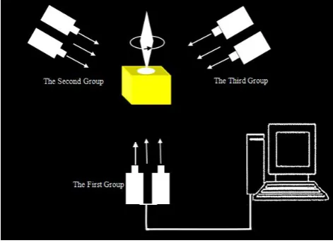
[image:2.595.187.423.371.543.2]Based on above 3 tasks, track system normally adopts riding position sensor and image handling techniques to analysis human postures. In order to monitor human spinning state with mark points from different orientations, the system need coordinate with multiple binocular camera systems so as to make good preparation for human sports posture data collecting. As Figure 1 shows, three binocular shaped cameras, their orientation included angle all are 120 degree, at the same time transfer data information during an intervals of time to computer for next analysis.
Figure 1: Gymnastics spinning postures vision track system compositions
In Figure 1, yellow cube is the schematic diagram of platform. The First Group--The Third Group represents CCD that is binocular camera system, white rhombus is gymnastic players schematic diagram, arrows show spinning directions.
Through setting of testing equipments positions in Figure 1, stereoscopic motion track can be done to gymnasts from different directions, wholly analysis of sports image can be made, choose camera in type SONY DCS753.
System parameters setting
As Figure 1 show that every group first camera positively towards world coordinate origins
O
, the 2nd camera position is equal to translation distanced
that reduces one camera along camera coordinate systemX
positive direction,the distance is 100mm, then use linear camera model to make calibration to it,if given
M
i,
N
i
to beimage coordinate,
X
i,
Y
i,
Z
i
represents space point coordinate, can use approximately linear transformation
1
1
1
31 32 3324 23 22 21
14 13 12 11
Z
Y
X
a
a
a
a
a
a
a
a
a
a
a
N
M
i i
(1)
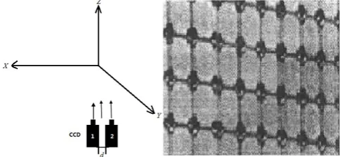
[image:3.595.180.431.262.377.2]In calibration process, each coordinate system corresponding relations as Figure 2 left picture shows. Coordinates corresponding relations should select according to areas required control points in actual sports process, this paper collects 10 data point to calibrate, applies generalized least square to calculate, images resolution ratio is 680×480. The collected 10 control points data in calibration experiment and correlations between computer images coordinate got from image analysis and actual world coordinate as Table 1 shows. Round profile feature marker as Figure 2 left picture shows, from which
M
,
N
represents corresponding point value in computer image ranks,X
,
Y
,
Z
represents actual world coordinate system, its minimum unit is millimeter [7]. [image:3.595.165.447.419.496.2]Figure 2: Schematic diagram of coordinate systems relations as well as network control points in camera calibration process
Table 1: Table of camera calibrated sample data
No. M N X Y Z No. M N X Y Z 1 38 239 175 129 580 6 456 68 276 -167 800 2 24 62 184 148 740 7 425 36 -240 -183 840 3 40 284 174 128 540 8 107 193 122 21 640 4 48 92 167 110 720 9 87 269 139 56 560 5 628 256 -455 -85 580 10 50 241 166 110 580
From formula(1) and Table 1’s 10 groups data, it can get equation set that composed of 20 equations including 11 unknowns, then apply generalized least square to make solution to it and can get transformation matrix
A
ij ,undercorner mark
i
represents group number of camera, under corner markj
represents left and right camera’s mark number, group numbers are 1,2 and 3, marker numbers are 1 and 2. The results are as Formula (2) shows.(2)
Gymnasts body mark point setting way
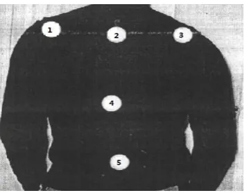
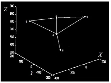
Figure 3: white small ball mark point location distribution schematic diagram
In Figure 3, point 1 and point 3 lie in gymnasts’ shoulders, test purpose of such two points is to judge shoulders gradient, point 2, 4 and 5 lie respectively in gymnasts crest three parts from top to bottom, and test purpose of these 3 points is to track crook degree in the direction of human crest. By cooperation among 1 to 5 mark points, posture information of human in spinning can be got.
In human spinning process, each mark point would change as body movements, camera system that composed of 3 groups’ camera can make better track in full orientation to mark points, and can fulfill human spinning states’ collecting and monitoring. In one moment of human spinning, it should take into consideration that only one or two cameras can fully observe 5 mark points location stick on gymnasts, so make use of cameras’ collected images that can test mark points.
[image:4.595.176.438.419.473.2]Video that camera collected can store as computer’s file with AVI format, use Direct X’s IMediaDet interface can extract one frame BMP image from AVI file. Method of IMediaDet: Get BitmapBits in the interface of ImediaDet is acquiring BMP format image in set time from media files, its interface form’s definition as Figure 4 shows.
Figure 4: BMP format image interface formal definition code
Interface parameters are respectively used to set images time in files, receive buffer location, image information files’ receive buffer location and images’ height width, one frame BMP image in required time can be got by such setting.
SPORTS IMAGE ANALYSIS
Human posture image analysis in a moment
Video is composed of lots of static images, video at one point is equal to one frame still-frame, and experiments make simulation of one group of images in the 1st group camera. In Figure 5, it shows left eye images after Gaussian smoothing filter, right eye images after Gaussian smoothing filter, left eye 200 threshold value binaries image and right eye 200 threshold value binaries image.
Figure 5: picture effect after still-frame image handling
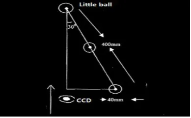
[image:4.595.104.507.627.700.2]balls which stick on gymnasts always change within special ranges in the vertical direction. So three intervals in experiment are respectively (1,150),(150,300)and(300,480),the minimum unit of interval is pixel. After cutting images into three, overlapping would happen among top division regions’ mark points. When observation angle becomes smaller, small balls’ overlapping probability would become bigger, however the highest overlapping that system designed is camera optic axis forms 30degree included angle with human shoulders small ball lines, as Figure 6 shows.
Figure 6: white little ball mark points maximum overlapping analysis schematic diagram
In Figure 6, values’ upward arrows pointing direction is observation direction. In experiment process, distance between shoulders is nearly 400mm, diameter of white little ball is 40mm, therefore as Figure 6 shows, only mark point radius is above 60mm under 30 degree condition . Based on above analysis, it can be known that if establish 3 pairs of binocular camera observation system with 120 degree; there always is one group’s mark point would not be sheltered, therefore it can be seen that such 3 complete mark points can make fully observation and handling to human body 5 stickup mark points.
Human posture image experimental data analysis flow
[image:5.595.160.453.429.616.2]Left and right eye images mark points data acquired through programming, then flow is done as Figure 7 shows, Figure 3 showed mark points data is worked out as Table 2 shows.
[image:5.595.204.407.661.742.2]Figure 7: Image mark points data handling flow figure
Table 2: Table of Binocular image experimental data
CCD I C S P 1 S P 2 S P 3 S P 4 S P 5
Left CCD
u
152 324 500 322 304v
92 60 42 252 454Right CCD
u
261 431 605 417 389v
90 54 40 256 450As Table 2 shows, the experimental data correspond to the 1st camera observed data, according to their own image transformation matrix, get relationships between image coordinate and world coordinate as formula(3) and (4) show.
1
993924
.
0
000050
.
0
000681
.
0
000062
.
0
707244
.
852
024453
.
1
302293
.
0
033754
.
0
800533
.
233
009146
.
0
246993
.
0
912428
.
0
1
Z
Y
X
v
u
L L (3)
1
000000
.
1
000053
.
0
000672
.
0
000048
.
0
758247
.
830
003670
.
1
491062
.
0
048897
.
0
043333
.
352
009136
.
0
247002
.
0
912326
.
0
1
Z
Y
X
v
u
R R (4) [image:6.595.215.399.387.525.2]It can be seen from formula (3) and formula (4) as well as Table 2’s data that world coordinate value as Table (3) shows and its unit is millimeter.
Table 3: Table of mark points world coordinate calculation results
W C S P 1 S P 2 S P 3 S P 4 S P 5
X 152 324 500 322 304
Y
92 60 42 252 454Z
261 431 605 417 389Note:W C show World coordinates; S P show Signs point.
From Table 3, 5 mark points space distribution status can be got as Figure 8 shows.
Figure 8: Gymnasts’ five mark points space schematic diagram in one moment
From Figure 8, gymnasts’ spine and shoulders bent degree can be known, its left shoulder lower than right ones, while upper body part tilts toward left body.
Sports spinning posture variance analysis
[image:6.595.208.406.642.757.2]Figure 9: Adjacent moment two frames mark points’ spatial location schematic diagram
In Figure 9, dashed part represents gymnasts’ five mark points space coordinate orientations composed image in previous moment, while solid part are that in later moment. Two frame mark points’ variant situations from previous moment to later moment indicate that human spinning direction is from top to bottom and in clockwise; gymnasts spin angular speed can be worked out according to time difference between two frames and gymnasts’ spin angles. Combine with mutual relations of adjacent frames, relative results of gymnasts upper posture changes in spinning process can be got, which plays correct role in aid training to gymnasts.
CONCLUSION
This paper on the purpose of human spinning posture analysis, took free spinning basic motions in rhythmic gymnastics events as research objects, made research on stereoscopic vision track system design method and sports analysis principles, stated camera calibration methods, applied data to calibrate camera inside parameters when mentioned in this paper, designed sports image analysis flow, put forward still single frame image mark point analysis method and adjacent two frames gymnasts’ five mark points spatial location transformation relationships, provided sports state and sports process analysis methods ,provided experimental platform and theoretical basis for physical education kinematic analysis and guiding as well as stereoscopic vision track perfect development. By analyzing human posture track system compositions, camera inside system parameters calibration and gymnasts back mark points setting methods, focused research on still-frame image mark points spatial location precise calibration methods, through which gymnasts mark points distribution conditions at some point was acquired, and finally analyzed adjacent frames image mark points spatial location distribution correlations, explored kinematic parameters that reflected in spinning process with two frames relationships.
REFERENCES
[1]Bing Zhang.International Journal of Applied Mathematics and Statistics,2013, 44(14), 422-430.
[2]Haibin Wang, Shuye Yang.International Journal of Applied Mathematics and Statistics,2013, 39(9), 243-250. [3]Hongwei Yang.Int. J. Appl. Math. Stat.,2013, 39(9), 188-195.
[4]Lei Gu.International Journal of Applied Mathematics and Statistics,2013, 44(14), 177-184. [5]Li Chun-Yan.Space control technology and application,2010, 36(3), 51-54.
[6]Wang Bao-Feng.Journal of aviation,2008, 29(1), 117-122.
[7]Wang Li-Chao.Laboratory research and exploration,2007, 26(3), 58-60.