Journal of Chemical and Pharmaceutical Research, 2012, 4(2):1426-1435
Review Article
CODEN(USA) : JCPRC5
ISSN : 0975-7384
Column Installation: Importance of a Properly Installed Column
Kaushal K. Chandrul and Anand
Shivdan Singh Institute of Technology and Management, UP, India
_____________________________________________________________________________________________
INTRODUCTION
The importance of a properly installed capillary column is under-appreciated in most cases. A poorly cut or installed column can lead to inferior chromatographic results. Also, permanent damage to the column may result if the proper installation precautions are not taken before column conditioning and use. Any gas chromatograph is limited by the weakest portion of the system column installation is a part of the system just as much as the column or the instrument itself. There is a large number of gas chromatographs in use. If is often stated that gas chromatography is the most common instrumental analytical technique in routine use. The availability of easy to operate, affordable and feature laden instruments has made GC a powerful analytical technique accessible to nearly every laboratory. Commercially available capillary columns of high quality have existed for about 25 years. For a number of reasons, many GC users are not extremely experienced in the practice of capillary gas chromatography. Many of these users do not possess a level of comprehension of the technique that allows them to prevent and solve many of the problems that commonly occur. Much of this comprehension comes from years of experience and the problems that accompany that experience. The combination of accessible instruments and capillary columns along with inexperienced users has created the need for practical information on the care, maintenance and troubleshooting of capillary columns and instruments.
1 Installing Fused Silica Capillary Columns
1.1 Column Installation Steps1: The basic column installation steps are the same for practically every column and GC system. Every precaution applies to all columns and situations. Some of the later steps are not necessary to properly install a column; however, they are verification of a proper installation and often prove to be very useful in the event that troubleshooting is necessary at a later date. The basic steps are:
1.Cutting the column 2.Installation in the injector
3.Turning on and verifying the carrier gas flow 4.Installation in the detector
5.Verifying column installation and detector operation 6.Conditioning the column
7.Setting the linear velocity 8.Performing a bleed test 9.Injecting a column test mixture
______________________________________________________________________________
used to cut columns and not other items or materials. Regardless of the tool, the basic technique is the same. The tips of a pencil or the edge of a wafer or sapphire tool are used as the cutting edge. Lightly scribe the polyimide coating with the cutting edge. The goal is to create a weak spot in the polyimide coating that exposes the fused silica tubing. Attempting to cut through the fused silica tubing with the cutting tool results in an uneven and unsatisfactory cut since the column is crushed in this area. Place a short length of the column against a finger or palm. This makes it much easier to feel how much pressure is being applied to the tubing by the cutting tool. The tubing fl exes if it is not supported which makes it difficult to control the amount of applied pressure. Lightly drag the cutting tool edge across the column in the desired location. Gasp the column 1–2 cm below the scribe mark. Gently bend the part of the column above the scribe away from the scribe mark. If properly scribed, the column breaks easily and evenly. If the column does not break, re-scribe the column about 1 cm below the previous scribe. Attempt to break the column again making sure it breaks at the point of the new scribe and not at the first one. A small amount of practice is required to consistently cut a fused silica column. After a while it becomes easy and routine; however, the cut should always be inspected regardless of one’s experience and skill. Sometimes the column breaks unevenly due to no fault or error in the cutting technique or method. It is recommended to inspect the column ends with a magnifier. After cutting, the ends of the column should be examined with a 10–20x magnifier to verify a clean and straight cut has been obtained. If the column end is jagged or uneven, re-cutting is necessary. The column needs to be re-cut until a satisfactory end is obtained. A poorly cut column may result in peak tailing or adsorption. Small pieces of the jagged edge of the column can fall into the column and cause severe peak tailing or blockage of the tubing. Small pieces may also enter the detector and cause it to malfunction. Regardless of the analysis, column or GC system, a good column cut is essential to obtain the best performance.
1.3 Column Placement in the GC Oven3: Most GC’s have a column hanger in the oven. Some hanger designs only allow one column to be placed on the hanger. If a second column is installed in the same GC oven, another approach has to be taken. Sometimes the second column can be hung directly on the cage of the first column. If this is not possible, there are usually several holes in the top of the GC oven where small pieces of wire or paper clips can be attached. The wire can be fashioned into a suitable hanger and the second column cage can be hung from the pieces of wire. Unwind enough of the tubing on both ends of the column so there is ample tubing free from the cage. The column should be placed in the GC oven so that there is no contact between the tubing and other objects in the GC oven such as column identification tags, oven walls, column hangers, etc. The forced air currents inside the oven cause movement of the column and these contact points may abrade the column. This may lead to breakage at these abrasion points since the polyimide has been weakened in these areas. Avoid tight or sharp bends in the tubing. These sharp bends place an excessive amount of stress on the tubing, thus increasing the possibility of breakage. The avoidance of sharp bends becomes more critical as column diameter increases. Large diameter tubing can not tolerate sharp turns or bends as well as small diameter tubing; therefore, it is more susceptible to breakage due to stress. Regardless of tubing diameter, it is much better to remove several centimeters of column length instead of subjecting the column to an extreme bend or turn. The loss of several centimeters has no affect on column performance.
______________________________________________________________________________
subjected to large changes in temperature. If a column is installed while the injector is cool, it is recommended to slightly tighten the column nut after the injector has reached the set temperature. The use of liquid leak detection fluids require the injector fittings to be below 100 °C.
1.5 Turning On and Verifying the Carrier Gas Flow5: Heating of a column without carrier gas flow results in serious and usually permanent damage of the column. Before the oven is heated after column installation, it is necessary to verify that there is a reasonable flow of carrier gas through the column. If there is a reasonable pressure on the gauge, it is often assumed that there is carrier gas flow in the column. This is not a completely reliable method. Flow controller or pressure regulator failures, or blockage in the gas lines or column can all create a pressure reading on the gauge; however, there is little to no carrier gas flow through the column. Damage to the column occurs upon subsequent heating. Worse is the damage to any replacement columns installed in the same GC with the same problem. The best method to verify column flow is very quick and simple. Place the end of the column in a small vial containing a light solvent (e.g., hexane, methanol). If there is carrier gas flow through the column, a steady stream of bubbles is visible. An absence or a very slow stream of bubbles indicates a problem. Check the GC system and gas supply, and make any adjustments or repairs before proceeding with column installation.
1.6 Column Installation in the Detector6: Column installation in the detector follows all of the same guidelines and precautions as for installation in the injector. The proper alignment of the nut and ferrule, a good column cut, the proper insertion distance and leak free connection are all important. Proper column installation in the detector may not be as critical as for the injector, but great care should be taken anyway. One of the carryovers from packed GC column usage is leaving the detector end of the column disconnected until the column is conditioned. While this is not absolutely necessary for capillary columns and does not result in any harm to the column or GC, it is still practiced.
1.7 Verifying Proper Column Installation and Detector Operation7: A leak allowing oxygen into the column or no carrier gas flow while the column is at higher temperatures (50 °C or higher) can rapidly damage a column. After the column is installed in the GC, the next step is conditioning the column at a high temperature. Before heating the column, it is best to verify the existence of carrier gas flow. The easiest and most secure method is to inject a non-retained compound into the GC while the oven is at 40–50 °C. A pressure on the column head pressure gauge is not always reliable. Do not heat the column above 50 °C before carrier gas flow is verified. Before injecting the non-retained compound, the detector needs to be on and the column head pressure set at an appropriate value.
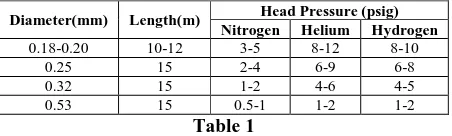
Diameter(mm) Length(m) Head Pressure (psig) Nitrogen Helium Hydrogen
0.18-0.20 10-12 3-5 8-12 8-10
0.25 15 2-4 6-9 6-8
0.32 15 1-2 4-6 4-5
0.53 15 0.5-1 1-2 1-2
Table 1
Table 1 lists the approximate head pressure ranges for some common column dimensions and carrier gases so that the linear velocity is set close to the recommended values. The head pressure (linear velocity) does not need to be exactly adjusted and set at this time; this is done later when setting the average linear velocity. The compounds used to verify carrier gas flow are the same ones used to set the average linear velocity.
Detectors Non retained compounds
FID Methane, Butane
ECD Methylene chloride, Dichlorodifluoromethane NPD Acetonitrile
[image:3.595.186.412.475.543.2]TCD,MS Methane, Butane, Argon, Air Table 2
1.A disposable lighter is a possible source of butane. Place the syringe needle into the flame outlet of the lighter. 2.Depress the small button allowing the gas to escape. Pull up 1–2 µl of the gas.
3.Headspace or diluted in solvent.
______________________________________________________________________________
5.Use a column temperature of 90°C or greater.
• Headspace: Fill an auto sampler vial with about 10 drops of solvent. Tightly seal the vial with a cap. Shake the vial for several seconds. Pierce the septum with the syringe needle, but do not insert the needle into the liquid. • Pull up 1–2 µl of the headspace above the liquid.
• Solvent dilution: Add 25–50 µl of the appropriate solvent to 10 ml hexane or isooctane and thoroughly mix. Inject 0.1–0.2 µl. Further dilution may be necessary depending on the sensitivity of the detector.
Table 2 lists some recommended non-retained compounds. One advantage of injecting a non-retained compound at this time is the additional information that is gained. The presence of a peak for the non retained compound confirms that the detector is on and that the data system is connected; the shape of the peak helps to confirm proper column installation. Avoid large volume injections or high concentrations since column overload can be misinterpreted as poor peak shape. Using a split injection works the best. If a peak does not appear, there is no carrier flow, the head pressure is set too low, not enough of the non-retained compound was injected, the detector is not functioning properly, or the recorder is not on or properly connected. It is absolutely necessary that a peak be obtained before proceeding. The peak obtained must be extremely sharp and without any tailing. If a broad or tailing peak is obtained, the following items should be inspected or checked:
1.Injector liner (breakage)
2.Position of the column in the injector and detector 3.Leaks in the injector and detector fittings
4.Leaks in the septum
5.Quality of column ends (i.e., poor cuts) 6.Ferrule or septum debris in the column 7.Split ratio (too low)
8.Inadequate makeup gas flow
1.8 Column Conditioning
1.8.1 Column Conditioning8: All columns have a small amount of volatile contaminants originating from their handling, installation and storage. Column conditioning involves heating the column to a high temperature to rapidly remove these contaminants. Conditioning is necessary any time a column is installed even if it has been previously conditioned. Failure to condition a column results in baseline problems. The baseline severely rises as the column is heated and numerous peaks, humps and blobs may be visible. While these contaminants do not foul or harm a detector, they are interferences in the chromatogram.
1.8.2 Conditioning Temperatures9: There are two approaches concerning the best temperature to condition a column. One is at the isothermal temperature limit of the column or 20–25 °C above the highest oven temperature that will be used without exceeding the upper temperature limit. Using the upper temperature limit conditions the column faster, but it may shorten column lifetime by exposing the column to unnecessarily high temperatures. If the highest operating temperature is more than 50 °C lower than the column’s upper temperature limit, conditioning at 20–25 °C above that operating temperature may be better. The drawback to conditioning at lower temperatures occurs if a higher column temperature needs to be used at a later date. The column usually has to be re-conditioned at a higher temperature to accommodate the new temperature conditions. Failure to re-condition the column may result in a rising and erratic baseline when the column temperature exceeds the previous conditioning temperature. The rate at which a column is heated has no impact on column conditioning. Rapidly heating a column does not damage it, thus slowly heating the column to the conditioning temperature is not necessary. A temperature program is not needed nor is repeated cycles of heating and cooling. The GC oven can be directly set at the conditioning temperature and the column heated at whatever rate the oven reaches this temperature. There is no evidence that temperature programming or cycling between temperatures improves conditioning or increases column life time or performance.
______________________________________________________________________________
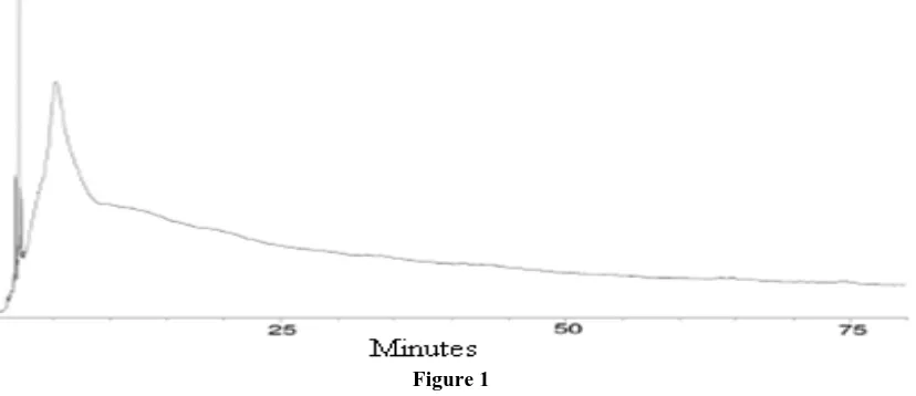
[image:5.595.94.508.255.434.2]lost and a short conditioning step is still needed. It is best to monitor the progress of column conditioning so that problems can be immediately noticed before column damage can occur. The detector should be already functioning due to the carrier gas flow verification step. Set the recorder or data system with a 120 minute run (stop) time and the attenuation or sensitivity setting used for the analyses. Input the conditioning temperature into the GC and start the recording device. The baseline should start to sharply rise after several minutes and continue to rise beyond the time when the GC oven reaches the set temperature. After 5–15 minutes at the conditioning temperature, the baseline should start to rapidly drop. After 30–90 minutes at the conditioning temperature, a steady baseline or detector signal should be obtained. As soon as the baseline is stable for more than several minutes, conditioning should be stopped. Usually the entire plot looks like a large blob with some peaks riding on top (Figure 1). Further conditioning reduces the baseline by only a very small amount and usually is a waste of time. More polar stationary phases, thick film columns and greater sensitivity settings usually require longer conditioning times. For very low level analyses (sub ppb), 4–8 hours of column conditioning may be required.
Figure 1
If the baseline is unstable or excessively high after 60–90 minutes, column conditioning should be stopped. Most likely there is a leak in the GC or a contamination problem. If there is a leak, the baseline remains at a high level since damage to the stationary phase is occurring. The high baseline is due to the elution of the degradation products of the stationary phase. Additional heating only further damages the column, thus conditioning should be stopped. The most common location of leaks is around the injector. Check the septum, column nut and all of the injector fittings for leaks. Be sure that the recording device is not set at one of its most sensitive levels. Normal but small deviations in the detector signal appear to be very large at these very sensitive settings. Contamination is primarily visible as an erratic baseline and/or the presence of various size and shape peaks. The GC is usually not suitable for use while contaminated, thus conditioning should be stopped so that the GC can be cleaned. A dirty injector or gas lines are the most likely source of any contamination. In some cases, installation of a new column into a contaminated injector results in a contaminated column. If this contaminated column is transferred to a different, contaminant free GC for troubleshooting purposes, the same problem arises. The incorrect conclusion that the column is defective may be reached when in fact the column was contaminated by the first GC system. A new column should not exhibit high bleed. High quality columns do not self destruct upon shipping or storage, and are tested for bleed levels during the manufacturer’s testing process. Some detectors require several hours to stabilize especially if they have been off for more than 1–2 hours. The most common detectors that exhibit this tendency are the ECD, NPD and MS. Upon monitoring the baseline, it may appear that the baseline does not stabilize and continues to drift downward. This drift may be due to detector stabilization. The column maybe fully conditioned, but the detector requires additional time to stabilize. It is difficult to determine whether the drift is column or detector related. Experience with a particular detector usually helps in determining the source of the baseline drift.
______________________________________________________________________________
monitored during conditioning. This makes it difficult to determine whether the column is fully conditioned. Also, ongoing damage to the column due to a leak at high temperatures can not be detected until significant damage has occurred. If a column is conditioned while disconnected from the detector, 10–20 cm of the free end needs to be cut off before installation in the detector. A small amount of air enters the end of the column and damages the stationary phase in this region. After the column is installed in the detector, a small amount of additional conditioning is still necessary. The process of handling and installing the column slightly contaminates the end of the column. This requires the column to be held for about 15 minutes at the conditioning temperature or until a stable baseline is obtained. Some detectors may require hours before they stabilize and a flat baseline is obtained.
1.9 Setting the Carrier Gas Average Linear Velocity12: The best time to accurately set the linear velocity is after the column is properly conditioned. The linear velocity can be set before conditioning; however, time is required for the column to stabilize (condition) at the temperature used to set the linear velocity. Since carrier gas flow has been previously verified, there is no need to set the linear velocity prior to conditioning. The retention time of a non-retained compound is used to set the average linear velocity. A list of recommended compounds can be found in Table 2. The desired average linear velocity and column length is used in Eq. 1 to determine the required retention time for the non-retained compound. The column head pressure is adjusted downward to increase the retention time and adjusted upward to decrease the retention time until the desired one is obtained. A retention time of ±0.05 minutes from the calculated value is sufficient in most cases.
tm =L/60u Eq.1
tm = retention time of a non-retained compound (min)
L = column length (cm)
u = desired average linear velocity (cm/sec)
The average linear velocity is dependent on the column temperature. It is important to set the linear velocity at the same temperature for a given analysis. Using a higher temperature results in a slower velocity and a lower temperature results in a faster velocity than desired. Changes in retention times and efficiency occur with the measurement error. Usually the initial temperature of a program is the most convenient. In practice, any column temperature can be used; however, a consistent temperature of measurement is the most important consideration. After the linear velocity is set, the column is ready to use. There are several more steps that are not necessary for the best performance of the GC system; however, they may prove to be very useful when troubleshooting problems.
______________________________________________________________________________
Column: DB-5ms, 30 m x 0.25 mm, 0.25 µm Oven: 100–325 °C at 15°/min, 325 °C for 15 min
Figure 2
1.11 Injecting Column Test Sample14: After the column has been conditioned and a bleed test run, some type of column test mixture should be injected and analyzed. There are two types of test samples. One is the same sample used by the column manufacturer to test a newly made column. The other is a representative or actual sample like the ones analyzed with the GC. Perhaps both can be used to test different aspects of the GC’s performance. Nearly every capillary column comes with a performance chromatogram generated using a specific test mixture. If the same conditions and sample are used, the chromatogram generated should be nearly identical to the one sent with the column. Large differences are indicative of a problem with the gas chromatographic system or perhaps the incorrect test conditions. When a good chromatogram is obtained, it should be stored for future reference. If a problem should arise in the future, the test mixture can be injected and the chromatogram compared to the one generated with the properly working system. The diagnosis of many problems can be accomplished with the proper interpretation of the results of the test mixture chromatogram. Each of the compounds in the test sample provides a specific bit of information about the column. This information is very useful when trying to troubleshooting column problems. Instead of a manufacturer’s test sample, a representative or actual sample can be used to test system performance. In some cases, this sample is a better test of the performance of the gas chromatographic system. Some analyses are less demanding of the column than the column test mixture. A column that appears to be bad with the column test mixture performs satisfactorily for the samples of interest. It is probably unreasonable to discard that column based on the results of the column test mixture when it adequately performs the desired analyses. Some analyses are more demanding of the column than the column test mixture. A column that appears to be good with the column test mixture performs less than satisfactorily for the samples of interest. While this is fairly uncommon, a different sample than the column test mixture is needed to adequately judge the performance of the column. Usually there are only a few compounds or peaks that place high demands on the column. The test sample should contain these compounds; the other sample compounds may not be necessary especially if they are not as demanding on the column. One simple method to monitor system performance is to make an overhead transparency of a reference test chromatogram. The transparency can be placed over a corresponding test chromatogram generated using the same conditions and printed in the same size as the one depicted on the transparency. Acceptable performance variations can be noted on the transparency. Factors such as peak retention, shape and size, and baseline rise can all be easily noted and measured even the most inexperienced GC user. For example, a box can be drawn around a reference peak on the transparency and the corresponding peak in the generated test chromatogram has to reside within the box boundaries to be acceptable. The need for system maintenance can be easily discovered before a major problem develops. Also, this helps to prevent the use of incorrect conditions or methods since the chromatograms will not match.
______________________________________________________________________________
cells are sealed, thus ferrule particles in the cell necessitate return of the detector to manufacturer and days of downtime. Over tightening graphite ferrule makes it difficult to re-use the ferrule multiple times. A graphite ferrule can be used 10–15 times providing it is not deformed by repeated over tightening. Graphite is much harder than graphite ferrules. This makes their properties the opposite of graphite ferrules. A leak free seal is more difficult to obtain with graphite ferrules since they are much harder. It is much harder to over tighten graphite ferrules. Graphite ferrules do not flake and are better suited for GC/MS and ECD systems. Graphite has the tendency to creep at higher temperatures. The ferrule changes shape upon heating. A leak free fitting at one temperature can leak at a different temperature. If the fitting temperature is changed by more the 25–30 °C, it is recommended to check the fitting for any leakage after it has reached the new temperature. Upon over tightening especially at higher temperatures, graphite ferrules usually stick to fused silica tubing. Often the tubing has to be cut since the ferrule does not come off of the tubing. Ferrule size is determined by the GC fittings and column diameter. The GC fittings governing the outer diameter and height of the ferrule. The most common outer diameter is 1/8” with a few 1/4” and metric sizes. This size does not refer to the outer diameter of the ferrule, but to the size of the fitting. The inner diameter is governed by the column diameter. There are three different ferrule inner diameters in common use. Table 3 lists the ferrule inner diameter need for the various column diameters.
Column Internal Diameter(mm) Ferrule(mm) 0.05-0.25 0.4
0.32 0.5
0.45 0.8
0.53 0.8
Table 3
3. Tightening Fittings16: Column nuts are often over tightened. This is due to all of the cautions about avoiding leaks and the damage they cause. It is tempting to use a lot of force when tightening the column nut. While this does not cause any real damage, most ferrules can not be re-used if they are seriously over tightened. This can be quite expensive over the course of a year and a number of column installations. There are several guidelines that can be used to avoid excessive tightening of fittings. Graphite ferrules are very easy to seal, thus little tightening of the fitting is needed. When using a new graphite ferrule, after tightening the column nut by hand, the column nut only needs to be turned about 1/4 of a turn using a wrench. Any more is using excessive force. A used graphite ferrule often seals in less than 1/4 of a wrench turn. It is easy to tell if the column nut is tight enough. If the column can not be pulled from the fitting, it will not leak. If the column moves during the pull test, make sure it is re-positioned in the proper location. Upon removal of the fitting, if the graphite ferrule is highly deformed or a portion has been forced through the opening in the fitting or column nut, the fitting was over tightened. Graphite ferrules are hard, thus more difficult to seal than graphite. When using a new graphite ferrule, after tightening the column nut by hand, the column nut only needs to be turned about 1/2 of a turn using a wrench. Column nuts on GC/MS transfer lines may require slightly more than 1/2 of a turn. Any more is using excessive force. A used graphite ferrule often seals in less than 1/2 of a wrench turn. If the column can not be pulled from the fitting, it will not leak. It is more difficult to over tighten a graphite ferrule. If the ferrules permanently stick to the fused silica tubing on a consistent basis, the fitting was probably over tightened.
______________________________________________________________________________
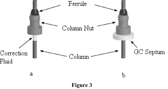
[image:9.595.159.444.130.281.2]The septum fits snugly on the column and holds the column nut and ferrule in the proper place during installation. The septum stays on the column during use, but it does not affect the column in any manner.
Figure 3
5. Leak Detection18: Detecting leaks can be a difficult task. There are many places where leaks can develop with the injector fittings being the most common area. Liquid leak detectors are often used to detect leaks, but they do not work in many applications. Using an electronic leak detector is the most convenient, but they are very expensive. They work on hot fittings which is not possible with liquid leak detection fluids. Liquid leak detection fluids are easy to use and inexpensive. The most common fluid is referred by the brand name of Snoop. When squirted onto a fitting, a leak becomes visible by the continuous formation of bubbles in the liquid. The absence of bubbles indicates that there is no leak present. A 50/50 mixture of iso-propanol and water can also be used as a leak detection fluid. Liquid leak detection fluids do not work on hot fittings. Most detection fluids have an upper temperature limit of 90–100 °C. Most injector and detector fittings are maintained at temperatures well above 100 °C. To check the fitting for leaks, it has to be cooled below 100 °C before the leak detector fluid can be used. Fittings often develop a leak upon heating especially if equipped with a graphite/vespel ferrule. If the fitting is leak checked at a lower temperature, tighten the fitting by about 1/16–1/8 of a turn after it has reached the higher temperature. One method to determine whether an injector or the gas lines leading into it are leaking is to use a static leak check. This involves pressurizing the injector and gas lines and checking the column head pressure gauge for a loss of pressure.
Applications
The goals of the above information provided the information for maximize both capillary column lifetime and the performance of the gas chromatographic system. The other goal is to provide an efficient and logical troubleshooting guide with the real intention to reduce or prevent performance breakdown problems from occurring. An in-depth knowledge of chemistry and chromatography is not required. This article, attempts to thoroughly explain every detail about Column Installation; it is intended as a practical guide so that the urge to hit the GC with a hammer as a last resort does not occur. In-depth technical information about GC techniques, instrumentation, specific applications and other details can be found in this article.
CONCLUSION
Chromatography has grown over the past century to be the central separation science; it has become the “bridge” (or the common denominator) for analytical methods. Instead of measurement of only one or several components in a sample, chromatography facilitates the separation, detection, identification, and quantitative measurement with selective detectors of usually all the components in a sample. Its characteristics of sensitivity, selectivity, versatility, and quantitative features on micro, macro, and preparative scales have led to its rapid expansion. The driving forces of chromatography include the persistence and creativity of scientists, their experimental investigations, their interrelated seminal concepts, their research journals and other publications, and the relevant scientific organizations.
REFERENCES
______________________________________________________________________________
[2] P. L. Dubin (ed.), Aqueous Size Exclusion Chromatography, J. Chromatography Library, Vol. 40, Elsevier, Amsterdam, 1988.
[3] T. G. Spiro, S. E. Allerton, J. Renner, A. Terzis, R. Bils, and P. Saltman, J. Am. Chem. Soc. 88:2721 (1966). [4] R. Tijssen, J. Bos, in Theoretical Advancement in Chromatography and Related Separation Techniques (F.
Dondi and G. Guiochon, eds.), NATO ADI Series C, Kluwer, Dordrecht, 1992, p. 397. [5] J. J. Kirkland, Adv. Chem. Ser. 234:287, (1994).
[6] H. Bu¨rgy and G. Calzaferri, J. Chromatography 507:481 (1990).
[7] W. W. Yau, J. J. Kirkland, and D. D. Bly, Modern Size Exclusion Chromatography, John Wiley and Sons, New York, 1979, pp. 31–36.
[8] C.H. Fischer, H. Weller, A. Fojtik, C. Lume-Pereira, E. Janata, and A. Henglein, Ber. Bunsenges. Phys. Chem.
90:46 (1986).
[9] C.H. Fischer, J. Lilie, H. Weller, L. Katsikas, and A. Henglein, Ber. Bunsenges. Phys. Chem. 93:61 (1989). [10]C.H. Fischer, M. Giersig and T. Siebrands, J. Chromatography A, 670:89 (1994).
[11]T. Siebrands, M. Giersig, P. Mulvaney, and Ch.-H. Fischer, Langmuir 9:2297 (1993).
[12]K. A. Littau, P. J. Szajowski, A. J. Muller, A. R. Kortan, and L. E. Brus, J. Phys.Chem. 97:1224 (1993). [13]C.H. Cai, V. A. Romano, and P. L. Dubin, J. Chromatography A 693:251 (1995).
[14]P. L. Dubin, S. L. Edwards, and M. S. Mehta, J. Chromatography A 635:51 (1993).
[15]M. G. Styring, C. J. Davison, C. Price, and C. Booth, J. Chem. Soc. Faraday Trans. 80:3051 (1984).
[16]E. J. W. Verwey and J. Th. G. Overbeek, Theory of the Stability of Lyophobic Colloids, Elsevier, New York, 1948.
[17]R. Rosetti, J. L. Ellison, J. M. Gibson, and L. E. Brus, J. Chem. Phys. 80:4464 (1984).