Study of stiffness effect of panel zone on ductility of RBS joint
8
0
0
Full text
(2) International Journal of Sustainable Construction Engineering & Technology. 1.0. INTRODUCTION. Most studies recommend usage of RBS joints. Experiments cover beam dimensions and steel types usually used in practice. Primary studies on this kind of joint suggest this joint have very suitable characteristics such as ductility, proper resistance, lower cost than other bending joints, lower run time of construction and installation of structure, and more reliance to welds. In this joint, by cutting some part of beam flange, plastic hinge is transferred from column side to inside beam, so that beam joint to column side is not threatened. Reduced area, by its plastic performance, absorbs more energy than joint to column side and creates a controlled hinge with extra ductility [3]. Re-hardening is a dominant feature of a RBS joint with radial cut, but it is lower than other post-Northridge joints [3]. Panel zone ductility is a parameter that affects on rupture of beams with RBS joints. Researches of Popov & Krawinkler showed that joints with weak panel zone experience brittle fracture of welds connecting beam flange to column flange, because of over shear deformation [3]. Although weak panel zone has a high energy-wasting capability, but it is not recommended because of the above reasons. By strong panel zone, although fracture probability is decreased, but probability of instability of beam is increased (especially in RBS joint). As usual, maximum bending stress is generated in beam flange and maximum cutting stress is generated in panel zone. If before beam reaches to its complete bending capacity, panel zone begins its rupture, then plastic hinge may be formed in beam, panel zone, or both. It is the reason that all seismic codes of practice in the world emphasize on reinforcing weak panel zones. This reinforcement is done by doublers and continuity plates. Seismic codes of practice offer various relations for these plates and their controls. Regarding to controlling nature of plastic hinge in RBS joints, any changes may have large effects on seismic behavior of this kind of joint [4]. Upon lab experiments in FEMA355D [6], it is less probable joints with weak panel zone reach to a great plastic rotation in sever earthquakes. Also, strong panel zone decreases performance of joints [4, 6]; while in joints with yielding capacity in shear for panel zone and with bending capacity of beam, a large rotation capacity is achieved. Regarding to the point that all test, except those of Deylami et al [4], have used US sections (Wxx), we used IPB and IPE sections that are common in IRAN to model panel zone effects on seismic behavior of RBS joint. The goal of these modeling is study of effects of panel zone on yielding and on inter-story drift angle in plastic area. In many researches, substructures are used to study joint effects on frame behavior. Substructures often are in T or cross shapes [3]. In analyzes by Deylami et al [4], a one-side modeling of joint (T-shaped substructure) is used. In such kinds of modeling, because of modeling a beam (corner joint modeling in common structure), little force is applied on panel zone, and forces are applied from on way to panel zone. So, study of models using two-side substructures seems necessary. Therefore, a two-side substructure is used in this paper. Eight models with various specifications are constructed and analyzed. Continuity plate is used in all models. Beam and column dimension are the same in four first and 2.
(3) International Journal of Sustainable Construction Engineering & Technology. second models, so that in first set IBP260 section is used for column and IPE300 section for beam, and in second set IBP450 section is used for column and IPE600 section for beam. Differences of each set are in reinforcement methods of panel zone, and there are no other changes in models. The only difference between these two classes is beam length. Beam length in first class is 2.50 m and in second class is 3.50 m. Column height in both classes is 3.40 m. 2.0. MODELING. Regarding to controlling nature of plastic hinge in RBS joints, any changes may have large effects on seismic behavior of this kind of joint [7]. Upon lab experiments in FEMA355D [6], it is less probable joints with weak panel zone reach to a great plastic rotation in sever earthquakes. Also, strong panel zone decreases performance of joints [4, 6]; while in joints with yielding capacity in shear for panel zone and with bending capacity of beam, a large rotation capacity is achieved [4, 6]. 2.1.. Designing panel zone. Shear force for panel zone is obtained from eq. (1) [6]. V pz =. ∑M. yield − beam. db. L L − dc. h − d b h . To study effects of panel zone thickness on seismic behavior of joint,. (1). V pz. ratio is used. Vy Vy is the ultimate shear limit in panel zone that is obtained from eq. (2). This value of coefficient in Iranian code of practice is 0.55 and in AISC is 0.6 (eqs. 1 and 2) [1, 5]. 3bc t 2f V y = 0.55 F y d c t cw 1 + d b d c t cw 3bc t 2f V y = 0.6 F y d c t cw 1 + d b d c t cw . . (2). . (3). Yielding in panel zone is so that it begins from center and goes toward corners. Deformation of panel zone is so that total shape is parallelogram. When this ratio is between 0.9 and 1, yielding is occurred in panel zone and beam simultaneously. When it is less than 0.9, panel zone is stronger than balance case and yielding occurs in beam [5]. When this ratio is greater than 0.9, panel zone is weak and yielding begins in panel zone. Studies of Chi et al (1998) and E.I. Tawil & Kunnath (1997) showed that panel zone deformation due to its yielding increases fracture probability in joint and decreases capacity in large rotations. FEMA offers a ratio between 0.6 and 0.9, but more the ratio is closer to 0.9, more balanced behavior joint has.. 3.
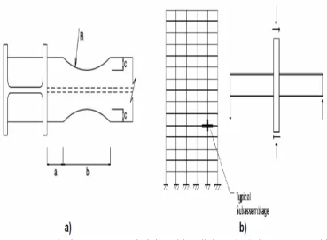
(4) International Journal of Sustainable Construction Engineering & Technology. 2.2.. RBS connection designing. To design RBS joint with radius cut, FEMA offered relations are used (eqs. 4, 5, 6, 7) [7], in which a, b, c, R are interval of beginning of cut area to column side, cut length, depth of cut and cutting radius, respectively (fig. 1.a). a = (0.5 ≈ 0.75)b f. (4). b = (0.65 ≈ 0.85)d. (5). c = (0.2b f ≈ 0.25b f. ). (6). 4c 2 − b 2 R= 8c. (7). Also, d and bf is beam flange wide and beam section height, respectively [7]. In designed models of this paper, a cut value of 50% is used, namely C=0.25bf. Cut values and a, b, c, R dimensions are given in table 1.. Figure 1.a) Designing parameters in joint with radial cut, b) Substructure used in modeling. Table 1. Section specifications in RBS joint. Beam Section a b c R IPE330 10cm 26cm 4cm 23.125cm IPE600 13cm 45cm 5.5cm 67.062cm. 4.
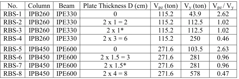
(5) International Journal of Sustainable Construction Engineering & Technology. 2.3.. Modeling. ANSYS software is used for modeling. Also, a cross-shaped substructure (fig. 1.b) is used. In most researches, substructures are used to study effects of joint on frame behavior. Substructures often are in T or cross shapes [3]. In this paper, a cross-shaped substructure is used to study effects of creating RBS joint on joint stiffness. In fact, loading in the lab is of drift type, which is applied from top of substructure. Load application style is illustrated in fig. 2. The multiplication value of column height by angle of substructure drift angle is used to obtain drift on peak of substructure model. This is same inter-story drift angle that by multiplying it in story height, inter-story drift is obtained, and can be used in modeling. Model specifications are given in table 1. To design panel zone, relations of section 2.1 is used. First model, called RBS-1, doesn't have doubler plate. Second model, RBS-2, uses two doubler plates with thickness 1 cm. In this model, these two plates are connected with groove welding to column web plate. Then, in calculation of panel zone capacity, equivalent thickness of column web plus doubler plate is used. In RBS-3, two continuity plates with thickness 1 cm are used. But, in this model the plates are not stuck to column web, and are modeled separately. Regarding to similar conditions of column web plate and doubler plates, cut capacity of panel zone is obtained from sum of tolerated cut of each plate. In two RBS-2 and RBS-3 models, panel zone thicknesses are equal, but joint styles are different. To study effects of a strong panel zone, RBS-4 is used. In this specimen, two doubler plates with thickness 3 cm are used in two sides of column web and are stuck to column web. Next four models have similar conditions of first four models, but they have different sections. Here, the difference between RBS-6 and RBS-7 models is joining style of doubler plate. Table 2. Shear values applied from beam to panel zone, its tolerable Shear. No. RBS-1 RBS-2 RBS-3 RBS-4. Column IPB260 IPB260 IPB260 IPB260. Beam Plate Thickness D (cm) Vpz (ton) Vy (ton) Vpz / Vy IPE330 0 115.2 43.9 2.62 IPE330 2x1=2 115.2 112.5 1.02 IPE330 2 x 1* 115.2 112.5 1.02 IPE330 2x3=6 115.2 250 0.46. RBS-5 RBS-6 RBS-7 RBS-8. IPB450 IPB450 IPB450 IPB450. IPE600 IPE600 IPE600 IPE600. 3.0. 0 2 x 1.5 = 3 2 x 1.5* 2x4=8. 271.6 271.6 271.6 271.6. 103.5 281 281 578. 2.63 0.96 0.96 0.47. HYSTERESIS DIAGRAMS OF MODELS. Here we study hysteresis diagrams obtained from analyses. These diagrams are drawn based on internal story drift angle by moment.. 3.1.. Diagrams of total substructure. Hysteresis curves are illustrated in fig. 2 to 5. Hysteresis curves for RBS-1, RBS-2, RBS3, RBS-4, RBS-5, RBS-6, RBS-7, and RBS-8 are shown in fig. 2 to 5, respectively. Two 5.
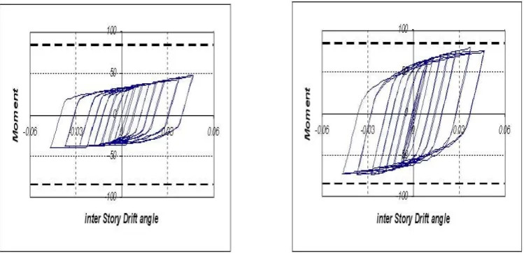
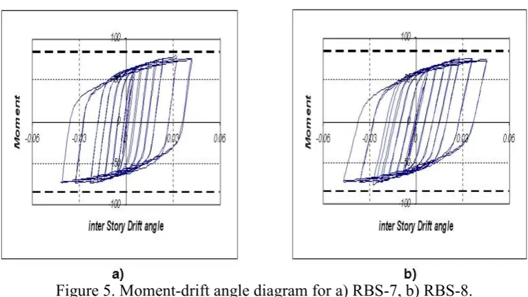
(6) International Journal of Sustainable Construction Engineering & Technology. dotted lines at above and bottom of diagram show beam maximum bending capacities. In these diagrams, moment is expressed in ton-meter (t.m).. Figure 2. Moment-drift angle diagram for a) RBS-1, b) RBS-2.. Figure 3. Moment-drift angle diagram for a) RBS-3, b) RBS-4.. Figure 4. Moment-drift angle diagram for a) RBS-5, b) RBS-6. 6.
(7) International Journal of Sustainable Construction Engineering & Technology. Figure 5. Moment-drift angle diagram for a) RBS-7, b) RBS-8. As illustrated in fig. 2 to 5, resistance of panel zone has a large effect on seismic behavior of RBS joints. Noticing fig. 2.a and 4.a that have weak panel zone, it is indicated that weak panel zone causes a decrement in moment applied to total substructure. In other specimens there are not dominant changes in diagrams. Moments of beam end (column side) and the value of moment in center of RBS joint are given in table 3. From table 3, it is indicated that in RBS-1, weak panel zone causes a decrement in applied moment on beam. Also, it is observed that moment ratio (maximum moment endured divided by maximum capacity of bending moment in reduced section of beam) in reduced area is about 1, which indicates little yielding in this area. So, RBS joint is not effective. RBS-5 has also a weak panel zone. Trend of this model is similar to RBS-1. But this trend is more sever so that reduced area remains in elastic state (moment ration is about 0.77). In other specimens, moment ratio on section capacity is about 1.241.33, which indicates development of plastic hinge in the area. Also, in all specimens, ratio of maximum moment on column side to maximum section capacity is less than 1, which indicates plastic hinge is not completed in column side and joint does not experience brittle fracture (due to more stress in column side area).it means that RBS connection works properly. Table 3. Maximum moment on column side and on reduced area, and their ratio. Specimens RBS-1 RBS-2 RBS-3 RBS-4. Mp 19.3 19.3 19.3 19.3. Mp(RBS) 12 12 12 12. RBS-5 RBS-6 RBS-7 RBS-8. 84.29 84.29 84.29 84.29. 55.10 55.10 55.10 55.10. MMax MMax(RBS) MMax / Mp MMax(RBS) / Mp(RBS) 13.57 12.32 0.70 1.03 17.13 15.55 0.89 1.30 16.32 14.82 0.84 1.24 17.55 15.93 0.91 1.33 47.36 78.08 77.98 75.76. 42.53 70.12 70.03 67.89. 0.56 0.93 0.92 0.9. 0.77 1.27 1.27 1.23. To more study of specimens and development process of hysteresis curves, we analyze hysteresis curves of substructure components. 7.
(8) International Journal of Sustainable Construction Engineering & Technology. 4.0. CONCLUSION o RBS joint with reduced section of beam flange increases structure ductility severely. In this type of joint, if designing is suitable, reduced section acts like a fuse and prevents plasticity of other frame components. o Regarding to the goal of RBS joint that is transferring plastic hinge, many factors influence on performance and efficiency of this joint. One of these factors is panel zone, so that weakness of panel zone can considerably decrease performance of joint. To achieve an optimal design, capacities of all components must be used so that panel zone and beam yield simultaneously and brittle fracture is avoided. Thus, in designing balance states, a 0.9 ratio of shear in panel zone to its capacity is recommended. o By studying effects of panel zone on seismic behavior of substructure with RBS joint, it is indicated that in specimens with RBS joints with a weak panel zone, plastic hinge didn't developed well, and ratio of applied moment of section capacity in two specimens were 0.77 and 1.03, whereas in other models (models with average and strong panel zone), this ratio is about 1.24-1.33, which indicates good performance of RBS joint. In specimens with strong panel zone, because of elastic behavior of panel zone, total wasted energy by substructure occurs in beam, so panel zone is not used efficiently. o Also, two specimens had equal doubler plate (RBS-3, RBS-3 and RBS-6, RBS-7). The only difference was in connection style of doubler plate. It was indicated that doubler plate style had a large effect, and if doubler plate hasn't been stuck to column web, wasted energy in panel zone is more than the case that the plates have been stuck to column web.. 5.0. REFERENCES. [1] Iranian code of practice for seismic resistant design of building “standard No.280005”. [2] A.Ghaznavi, M.Gerami, “Evaluation Of Cyclic Response Of RBS Connwction Including Panel Zone Effects”, First Disaster Management Confrence, University of Tehran, Tehran, Iran, Jan 2006. [3] A.Ghaznavi, “Behavior of steel moment resisting frame with RBS connection for seismic design” ,M.SC thesis of civil engineering, Semnan University, Iran, April 2007. [4] A.Moslehi Tabar , A.Deylami , “Instability of beams with reduced beam section moment connections emphasizing the effect of column panel zone ductility” , Journal of Constructional Steel Research 61 (2005) 1475–1491. [5] AISC (1999). ,Seismic Provisions for Structural Steel Buildings (1997), Supplement No. 1, American Institute of Steel Construction. [6] Roeder C. ,The state-of-the-art report on connection performance. FEMA 355d. Washington, DC: Federal Emergency Management Agency, 2000. [7] Federal Emergency Management Agency. ,Recommended seismic design criteria for new steel moment-frame buildings. Report no. FEMA-350; 2000. 8.
(9)
Figure
Related documents
LEASEPLAN DRIVER TRAINING RESULTS DRIVING TIME AVERAGE REVS AVERAGE SPEED AVERAGE.
The knowledge and skills acquired in Information Technology enable learners to use information and communication technology (specifically computers) in social and economic
Data that is stored after ToolsNet 4000 is installed and put into backup mode can be viewed in the both the ToolsNet 3000 and ToolsNet 4000 web applications... Configuration
The wide size range sampled and the presence of a juvenile, indicate an interesting habitat for studying the presence and growth of Scyllarides latus in the Straits of
This paper is an attempt to measure the economic efficiency of Dedza smallholder Irish potato (Solanum tuberosum) farmers in Malawi using a translog cost frontier,
Model Curriculum Model Curriculum Means to communicate Means to communicate Branding degree concept Branding degree concept Source of ideas
The aim of this thesis is firstly to determine the existing pains and gains of customers who purchase and drive trucks to and from urban construction and building projects, and then
Master of Science in Space Systems Operations-September 2001 Advisor: Charlie Racoosin, Naval Space Systems Academic Ciiair Professor Second Reader: John Van Hise, Jr., Department
