ii
MULTI FINGERED ROBOT HAND IN INDUSTRIAL ROBOT APPLICATION USING TELE-OPERATION
MUHAMMAD ATIF YAQUB
A thesis submitted in fulfilment of requirement for the award of the
Degree of Master of Electrical Engineering
Faculty of Electrical and Electronics Engineering University Tun Hussein Onn Malaysia
vi
ABSTRACT
ix
CONTENTS
ACKNOWLEDGEMENT V
ABSTRACT VI
LIST OF PUBLICATIONS AND AWARDS VII
CONTENTS IX
LIST OF FIGURES XIV
LIST OF TABLES XVIII
LIST OF APPENDICES XIX
CHAPTER 1 1
INTRODUCTION 1
1.1 Problem statement 2
1.2 Robot Reprogramming 3
1.3 Worker Safety 4
1.4 Objectives of the Project 6
1.5 Scope of the research 6
1.6 Thesis Structure 7
CHAPTER 2 9
LITERATURE REVIEW 9
2.1. Types of Robotic Hands 9
2.2. Techniques for Dexterity in Robotic Hands 10
2.3. History of Robotic Hands 11
2.3.1. MIT MH-1 12
2.3.2. Soft Gripper 12
2.3.3. Stanford/JPL Hand 14
2.3.4. Okada Hand 15
2.3.5. Utah/MIT Hand 16
2.3.6. Toshiba Hand 17
2.3.7. National Taiwan University (NTU) Hand 19
x
2.3.9. Robonaut Hand 22
2.3.10. Distributed Touch Sensor Hand 23
2.3.11. DLR Hand 25
2.3.12. High Speed Catching Hand 27
2.3.13. Hydraulic Hand 28
2.3.14. Kanazawa Hand 30
2.3.15. DEX Hand 31
2.3.16. Shadow Hand 32
2.4. Teleoperation 34
2.4.1. Bluetooth 35
2.5. Commercially available robotic hands 36
2.6. Actuators 36
2.7. Summary 37
CHAPTER 3 38
RESEARCH METHODOLOGY 38
3.1. Research process 38
3.2. Theoretical foundation of robotic hands 40
3.3. Dynamic Hand Modelling 46
3.3.1. Extension movement 48
3.3.2. Deflection movement 49
3.3.3. Spherical movement 50
3.4. Mathematical Model 51
3.4.1. Free body diagram 51
3.4.2. Differential Equation 52
3.4.3. Transfer Function 54
3.4.4. Constant Parameters 55
3.4.5. Sensor Gain/Model 56
3.4.6. Step Response 57
3.4.7. Ramp Response 57
3.5. SolidWorks Design 58
xi
3.7. Fabrication of working Model 59
3.8. Controller Design and Implementation 60
3.9. System Integration 62
3.10. Testing and results 63
3.11. Data Analysis 63
3.12. Summary 63
CHAPTER 4 64
MECHANICAL DESIGN 64
4.1. Finger Design 65
4.1.1. Distal Segment 66
4.1.2. Middle Segment 67
4.1.3. Proximal Segment 68
4.2. Palm Design 71
4.3. Hand Assembly 72
4.4. Fabrication Process 73
4.4.1. Rapid prototyping 74
4.4.2. Aluminium fabrication using CNC machine 76
4.5. Frame Construction 79
4.6. Muscle Assembly 81
4.7. Motion Mechanism 83
4.8. Summary 86
CHAPTER 5 87
ELECTRONIC CONTROL DESIGN 87
5.1. System Overview 87
5.2. Master Glove Module 88
5.2.1. Bend Sensor 89
5.2.2. Analog to Digital Conversion 90
5.2.3. Microcontroller 92
5.2.4. Firmware Development 94
5.2.5. Schematic and Assembly 97
xii
5.3.1. Bluetooth Module 101
5.3.1.1. Bluetooth Radio Layer 102
5.3.1.2. Baseband Layer 102
5.3.1.3. Link Manager Protocol (LMP) 103
5.3.1.4. Host Controller Interface (HCI) 103 5.3.1.5. Logical Link Control and Adaptation Protocol (L2CAP) 103
5.3.1.6. RFCOMM 104
5.3.2. Solenoid Valves 104
5.3.3. Feedback Sensors 107
5.3.4. Microcontroller 108
5.3.5. Firmware Development 110
5.3.6. Schematic and Assembly 113
5.4. Summary 117
CHAPTER 6 119
SYSTEM INTEGRATION 119
6.1. System Initialization 119
6.2. Communication Channel Establishment 120
6.3. Debugging Terminal 120
6.4. Modules Testing 122
6.4.1. ADC Testing 123
6.4.2. Connection Testing 123
6.4.3. Output Expander Testing 124
6.4.4. Darlington switch IC Testing 124
6.4.5. System Testing 125
6.5. Summary 126
CHAPTER 7 127
RESULTS AND DISCUSSION 127
7.1. BendSensor Data 127
7.2. ADC resultant data 129
7.3. Connection establishment result 130
xiii
7.5. Darlington Switch results 133
7.6. System Results 134
7.7. Denavit-Hartenberg Model 138
7.8. Torque Analysis and Modelling 148
7.9. Summary 155
CHAPTER 8 156
CONCLUSION AND RECOMMENDATIONS 156
8.1. Conclusion 156
8.2. Recommendations 159
xiv
LIST OF FIGURES
Figure 1.1 Reprogramming Required for change in material 4
Figure 2.1 Soft Gripper 1 13
Figure 2.2 Soft Gripper 2 13
Figure 2.3 Soft Gripper 3 13
Figure 2.4 Stanford/JPL Hand 14
Figure 2.5 Okada Hand 16
Figure 2.6 Utah/MIT Hand 17
Figure 2.7 Toshiba Hand 18
Figure 2.8 NTU Hand 20
Figure 2.9 DIST Hand 21
Figure 2.10 Robonaut Hand 23
Figure 2.11 Hand with distributed touch sensor 24
Figure 2.12 DLR-Hand II 26
Figure 2.13 Latest version DLR-Hand 27
Figure 2.14 High Speed Catching Hand 28
Figure 2.15 Hydraulic Hand 29
Figure 2.16 Kanazawa Hand 30
Figure 2.17 Dexhand 32
Figure 2.18 Shadow Hand 33
Figure 3.1 Stepwise research process 39
Figure 3.2 Systematic teleoperation diagram 40
Figure 3.3 D-H reference frames 41
Figure 3.4 D-H parameters 42
Figure 3.5 D-H parameters for the robotic hand 43
Figure 3.6 Model for the hand 47
Figure 3.7 Movements of the finger 47
Figure 3.8 Extension movement of the finger 48
xv
Figure 3.10 Spherical movement of the finger 50
Figure 3.11 Free Body Diagram of the Plant 52
Figure 3.12 Sensor Model 56
Figure 3.13 Sensor Model Simplified 56
Figure 3.14 System Model using Transfer Function in MATLAB 57 Figure 3.15 Step Response of system with Kp = 500 57
Figure 3.16 SolidWorks Mechanical design 59
Figure 3.17 Controller design schemes 61
Figure 3.18 Control diagram of robotic hand 62
Figure 4.1 Parts of finger 65
Figure 4.2 Front, Right and Back view of Distal Segment 66 Figure 4.3 Front, Right and Back view of Middle Segment 68 Figure 4.4 Front, Right and Back view of upper proximal segment 69 Figure 4.5 Front, Right and Back view of lower proximal Segment 70 Figure 4.6 Front, Right and Back view of lower proximal Segment of thumb 70
Figure 4.7 Views for the front part of palm 71
Figure 4.8 Front and back views of robotic hand 73
Figure 4.9 Fabrication process 75
Figure 4.10 Comparison of human hand VS assembled Model 75
Figure 4.11 CNC machine processing the part 77
Figure 4.12 Fabricated parts using Aluminium 77
Figure 4.13 UTHM Hand Vs Human Hand 78
Figure 4.14 Assembled UTHM Hand 78
Figure 4.15 Top plate for stopping and holding the springs 79 Figure 4.16 Bottom plate for solenoid valve mounting 80 Figure 4.17 Pneumatic muscle used in project 81 Figure 4.18 Pneumatic muscles assembled in frame 82 Figure 4.19 Tendon Strings attached to pneumatic muscles 83 Figure 4.20 Tendon Strings Routing Mechanism 84 Figure 4.21 Tendon Strings Routing Mechanism for abduction and adduction 85
xvi
Figure 5.2 Master Glove Module block diagram 88 Figure 5.3 BendSensor and glove used in system 89
Figure 5.4 Location for sensors 89
Figure 5.5 BendSensor used in voltage divider 90
Figure 5.6 ADC Configuration 92
Figure 5.7 mbed microcontroller board 93
Figure 5.8 Flowchart of Firmware for Master Glove 96
Figure 5.9 Schematic of Master Glove Board 98
Figure 5.10 Operator wearing Master Glove 99
Figure 5.11 Robotic hand module block diagram 100 Figure 5.12 Closed loop system of robotic hand 101 Figure 5.13 Architecture for USB Bluetooth device 102
Figure 5.14 Solenoid Valve 105
Figure 5.15 Pulse width VS Flow rate 107
Figure 5.16 BendSensors mounted between and at the back of fingers 108
Figure 5.17 Output Expansion configuration 110
Figure 5.18 Flowchart of slave robotic hand module 112 Figure 5.19 Schematic of slave robotic hand module 115 Figure 5.20 Controller board mounted on the muscle assembly 116
Figure 5.21 Tee joint assembly 117
Figure 6.1 Starting screen of Tera Term Version 4.71 121 Figure 6.2 Serial port setup in Tera Term Version 4.71 122
Figure 6.3 Complete integrated system 126
Figure 7.1 BendSensor calibration data 128
Figure 7.2 Comparison of raw and filtered data 128
Figure 7.3 Serial output of ADC 129
Figure 7.4 ADC data from master glove 129
xvii
Figure 7.9 PWM signal from output expansion chips 132
Figure 7.10 High Power PWM signal 133
Figure 7.11 Index finger and middle finger bent under thumb 134 Figure 7.12 Ring finger and pinkie finger bent under thumb 135
Figure 7.13 Object holding test 136
Figure 7.14 Step response of distal segment of thumb 137 Figure 7.15 Ramp response of distal segment of thumb 137 Figure 7.16 Denavit-Hartenberg reference frames 138
Figure 7.17 Finger and joint labels 139
Figure 7.18 Comparison of joints angles of UTHM hand with human hand 142 Figure 7.19 Sensor locations for the master glove 149
Figure 7.20 Description of joint angles 149
Figure 7.21 Torque illustration 153
xviii
LIST OF TABLES
Table 7-1 Denavit-Hartenberg parameters 140
Table 7-2 Table for kinematic structure details 141
xix
LIST OF APPENDICES
APPENDIX TITLE PAGE
A BendSensor Characteristics 169
B ADC MCP3208 Guide 173
C Expansion Chip MCP23S17 Guide 176
D Quad Darlington Switches 178
E Source Code for Master Glove 182
CHAPTER 1
INTRODUCTION
Robots have become an integral part of modern human life. With every passing year the population of robots are being increased. The industry has replaced a large number of human workers with lesser number of robots on the grounds of economy and efficiency. A robot is a modern version of slave, which perform any task in its capacity satisfying the old human instinct to rule. A robot follows the command as ordered by the human master. Therefore the humans can still enjoy mastering a thoughtless, speechless but efficient slave under their authority.
Hands have been thought of being the key to the intelligence of humans. Aristotle and Anaxagoras had been discussing this matter hundreds of years ago [1]. Among all the creatures inhabiting this earth, humans are the only living being that have been gifted with this kind of hands. These hands are capable of doing many tasks in our daily routine like dexterously handling different things and even sensing. Human hand has been an area of interest and research since the advent of intellect and has been considered to be one of the reasons that human intelligence is superior to all living creature on Earth. It has been confirmed by the several findings of paleoanthropologists, showing that the mechanical dexterity of the human hand has been a major factor in allowing Homo sapiens to develop a superior brain.
2
few decades which range from the simplest design of parallel jaw grippers to complex configurations of dexterous multi-fingered hands.
While the human hand’s dexterity has been admired since the oldest times, it is still an unmatched standard for artificialists. There have been many artificial hands made till date that have been showed to be stronger and faster than the human hand but still in the broader spectrum of dexterous manipulations it cannot match the human hand. It is therefore natural for an engineer to take inspiration from such a design success, and set forth for himself the goal of building hands that achieve, though partially, such capabilities. The toolbox of Mother Nature containing actuators, sensors, and control elements is unmatchable and superior to the resources of latest technology. Hence, the question whether artificial hands should look like those of humans is not quite settled. The answer is application specific and depends on what is expected from the hand. Because functions of human hands are multi faceted and variable, therefore there is no robotic hand that can compete with it. Only for specific application the robotic hands are more robust, strong and efficient.
In tele-operation normally the master-slave configuration is used. Master is a human operator that commands the slave robotic hand to do useful work. In this project the human operator will wear a master glove that will be embedded with sensors to detect the motion of the human operator. The data from the motion of the fingers of human operator will then be sent to robotic hand that will follow the motion.
1.1 Problem statement
3
it can be seen that even for a little change, the robot has to go through lengthy reprogramming process. Solution for this problem is tele-operation in which the robot can be controlled by a human from a certain distance.
We have to design and develop an anthropomorphic dexterous multi-fingered hand, for the industrial purpose, in order to get the precise and accurate grasp. It should mimic flexibility and sensitivity of the actual human hand. Also as mentioned before, the reprogramming problem of robots must be overcome. There is lot of losses that the industry faces due to human errors so they have to discard a certain number of damaged products. The robotic hand will also overcome this problem as it will be precise in handling objects. Also there are certain places that are harmful for humans like very high temperature or any hostile environment where there is a risk of injury to the worker, so in these places our robotic hand will replace the human operator. As it will be controlled using tele-operation by a human therefore it will act like the worker is handling the objects in that hostile environment.
1.2 Robot Reprogramming
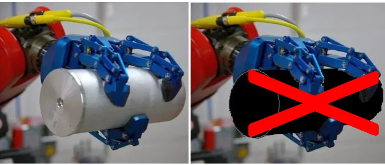
This robotic hand system also provides the solution for the robot reprogramming system. The robotic systems are programmed for their specific use. Therefore when there is a change in the task, the robotic system must be reprogrammed or replaced by new robot. To fix this problem, this project has used tele-operation.
4
Figure 1.1 Reprogramming Required for change in material
In the last scenario only the material has been changed while the size and other features were kept constant, still there was a need for the reprogramming. This shows the severity of this problem. Even a small change can cause the assembly line to acquire a new robot or at least reprogramming of robot. But with this project as the information of gripping is provided in real time, therefore it can adjust the force applied by the hand. Therefore the robotic hand operated by tele-operation is providing a solution to the robot reprogramming problem faced by industry.
1.3 Worker Safety
The robot hand is intended to be used in the industrial applications. In industry there are workers who are working in hostile environments. They fulfil their tasks by putting their lives in danger. Every year there are many cases of industrial accidents in which the workers get injured, lost part of their body or in some cases get fatal accidents. The industries that have a high rate of accidents involve but not limited to;
• Metal melting industry
• Chemical industry
5
• Atomic reactors where high radiation levels are observed
• Space Exploration
• Mining
The metal melting industry puts workers in very high temperature environments. They deal with metals with very high temperature that can easily subject them to burning. In the chemical industry the workers are dealing with highly acidic chemicals and other highly reactive materials. The processes inside the chemical industry can produce harmful gases that the workers are subjected to inhale. In cutting industry the workers are using big and high speed blades and even lasers. They are subjected to the cutting injuries from the blades. In the atomic reactors the workers are subjected to high radioactive environments. The radioactivity can cause many health problems even cancer. In the space exploration the astronauts that are sent to the space require a lot of things to survive whereas a robot is independent. When the astronauts are working outside their shuttles in open space they are attached by a rope like link. If this link is broken they will be out of the reach of the world forever. In the mining industry the workers are subject to breathing problems because of the environment inside the mines. The workers are often subjected to the fatal accidents that are caused by the mine collapse. The list for this kind of industries and their hostile environments is too big to be covered here. This is just a brief summary of actual facts to prove the severity of problem.
6
1.4 Objectives of the Project
The main objectives of this project are defined as follows:
1. Designing, fabricating and implementation for the robotic hand.
2. Design of the master glove that human operator will wear to guide the robotic hand movement.
3. Establishment of communication channel, between the master glove and the slave humanoid robotic hand, for the transfer of information about motion of master hand.
1.5 Scope of the research
7
1.6 Thesis Structure
Chapter 1 provides brief description to the robotic systems. It describes the link between the hand and human brain. The chapter briefly compares the work of artificialists and Mother Nature. It introduces to the problem faced in this field and the objectives of this project. It describes about the system configuration and its scope.
Chapter 2 describes the literature review in the field of robotic hand and grippers. The analysis and discussions about the robotic hands made till date from the very beginning has been provided in this chapter.
Chapter 3 provides the information of the process of research and development used in this project. It builds the theoretical foundation of the project. It completely describes the flow of progress of this project.
Chapter 4 provides the information about the detailed mechanical design of the project. It depicts all the fingers and their joints with their motions. It describes the complete structure of the robotic hand and its motion mechanism. It also gives the detailed description of the pneumatic muscles used and their assembly. Finally it provides the mathematical modelling of the fingers according to their movements.
Chapter 5 provides the full information of all the electronics involved in the system. It describes the working of all the components used in the system. It establishes clear views of the working and flow of the firmware of both the master and slave. Finally it provides the mathematical modelling of the torque produced at the robotic hand.
Chapter 6 discusses the integration of complete system. It provides the information of the testing methods and the debugging tool. It also mentions the problem solved by the system in detail.
8
CHAPTER 2
LITERATURE REVIEW
This chapter provides a detailed overview of different techniques used in developing the robotic hand. It will also help in understanding the different types of hand that were in use throughout the history of robotics and the problems that arise.
2.1. Types of Robotic Hands
There are different types of robotic hands, such as for industrial purpose, for rehabilitation and for the purpose of research to understand the human structure and functioning of hand. The focus in this project study will be on the anthropomorphic hands and grippers. If the system is to use the same interface with the environment that was designed for the human hand (such as handles, consoles, tools etc.), then an anthropomorphic hand can best fit the task. Anthropomorphic hand is one that mimics an actual human hand. So anthropomorphic hands are dexterous in nature as they have the tendency to dexterously manipulate the objects they come in contact with.
10
difficult task, which contributed to the scarce penetration of robot hands in practical applications. On the contrary, an anthropomorphic machine hand can be taught directly by “demonstrating” the desired human behaviours in manipulation and grasping. In such systems, easily available sensorized gloves, or in some cases mechanical masters, are used to provide measurements of the master’s hand movements.
2.2. Techniques for Dexterity in Robotic Hands
For the object manipulation different techniques had been practised by researchers. One of the techniques is regrasping [3] and finger gaiting [4]. It comprises of a sequence of grasps until the object is held firmly in hand. But regrasping can be time consuming as there can be a need for grasping and releasing until the final firm grip. Also there can be problem when manipulating irregular shaped 3D objects which have quite little number of stables grasp position as the hand can leave the object during the process of regrasping.
Both the finger gaiting and regrasping involves kinematics and dynamics of manipulation, effect of gravity, slipping and the contact or detachment of one finer from the object. So this comprise of a hybrid system with some part event-driven and some part time driven. Thus the stability analysis and verification of these techniques are tricky.
11
Another problem in this area is the synthesis of sets of contact locations for selectively preventing and allowing slippage motions of grasped objects. The modelling for this technique is also difficult as modelling the friction at different surfaces has always been a big challenge for researchers.
In tele-manipulation/tele-operation [7], [8], [9], [10] and [11] movements of the master hand are replicated by the anthropomorphic slave device. A feeling of “immersion” of the operator in the remote (possibly virtual) environment may be enhanced by the good match of the machine hand functions with the natural ones, although there exist examples of non strictly anthropomorphic hands intended also for remote operation.
In between the completely unstructured world and the perfectly defined environments, there is a whole gray scale of applications where the familiar flexibility/efficiency tradeoffs have to be sought for actively. This concept is well rooted in the robotics community. Design of devices for this class of problems usually obeys the good old engineering principle of minimalism: choose the simplest mechanical structure, the minimum number of actuators, the simplest set of sensors, etc., that will do the job, or class of jobs. For the complexity measure the number of actuators for manipulation in one robotic hand can be seen. The minimum number of actuators in the hand for dexterous manipulation is nine, but for a complex hand structure the number of actuators can go up to 32 [2].
2.3. History of Robotic Hands
12
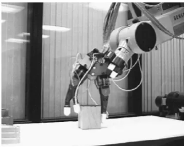
2.3.1. MIT MH-1
In Heinrich’s MH-1 a mechanical servo manipulator has been adapted for operation by the TX-0 computer [12]. The sensors on the mechanical hand gave information to the computer; the program processes this information, and the computer controls the motors that move the hand. The MH-1 system performs more than just the speed control and position control; it performs in accordance with a pre-recorded program that has been written by a programmer after a careful analysis of the real world with respect to the broad description of the tasks to be performed. Thus it could select appropriate routines by itself and find out what to do in unexpected situations for which the programmer has not provided an explicit instruction.
For example one program consisting of nine statements will make the hand do the following: Search the table for a box, remember its position, search the table for blocks, collect them and put them in a box. As a test of built-in mechanical intelligence if the box was taken away from the original position while the hand is searching for blocks, MH-1 will remember the new position of the box and continue to work with it as soon as it realized the change in the position by bumping into the box while searching for blocks.
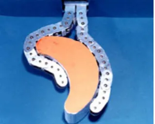
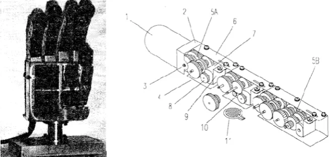
2.3.2. Soft Gripper
13
Figure 2.1 Soft Gripper 1 Figure 2.2 Soft Gripper 2
Figure 2.3 Soft Gripper 3
[image:26.595.128.288.107.235.2] [image:26.595.260.377.310.450.2]14
vertical and horizontal grasps was also developed. Soft gripper 3 was a belt driven model with three fingers.
2.3.3. Stanford/JPL Hand
[image:27.595.241.433.465.616.2]Salisbury and Mason 1985 showed first that theoretically the least number of degrees of freedom to achieve dexterity in a robotic hand with rigid, hard-finger, non-rolling and non-sliding contacts, is nine [14]. From this statement we can extract that there should be three fingers with each finger exhibiting three degrees of freedom for complete manipulation or gripping of an object. The practical demonstration of this work is the development of Stanford/JPL hand. The Salisbury or Stanford/JPL Hand was consequently designed to have nine joints, evenly distributed in each finger so as to optimize a measure of individual “manipulability” of the finger. Each finger had three DOF and is driven by four motors through tendon cables, two parallel axis joints provide rotation and the third proximal joint, perpendicular to the other joints, provides the sideward motion.
Figure 2.4 Stanford/JPL Hand
15
2.3.4. Okada Hand
Some researchers developed their version of hands by adding more degrees of freedom instead of just 3. By adding more degrees of freedom they can have more flexibility of use. Example of one successful design is from Tokyo, Japan in 1979 by Tokuji Okada [15]. He developed a three finger design but with different number of joints and hence different degrees of freedom in each finger. He added four joints in two fingers and one thumb with three joints. This hand also uses finger gaiting in the process of manipulating the held object. Finger gaiting is the technique in which one finger is repositioned on the surface of the object. By using this technique Okada hand can grip the objects more firmly.
16
Figure 2.5 Okada Hand
2.3.5. Utah/MIT Hand
After the seminal work done with the Utah/MIT Hand [16], hands of this type have been built in several labs. The objectives of this hand were; firstly, it will permit the experimental investigation of basic concepts in manipulation theory, control system design and tactile sensing and secondly, it will expand understanding required for the future design of physical machinery and will serve as a “test bed” for the development of tactile sensing systems. The Utah/MIT had three fingers and one thumb each having four joints and in total having 16 degrees of freedom with 32 tendons. Two tendon cables for each joint were used and each tendon cable was attached to the tendon tension sensor to track the torque imposed on individual joints. The positioning and tension sensing of this anthropomorphic robotic hand was done by using magnetically sensitive Hall Effect sensors. The actuators for the robotic hand were placed outside of the hand due to space requirements. Complex actuation pneumatic system is used for the actuation consisting of actuating cylinder, adjustable pneumatic dampers and spring tensioning systems within cylinders. The Tendons are routed throughout the hand via sequences of pulley induced bends and axial twists.
17
[image:30.595.204.436.245.415.2]behaviour such that tendon tensions were closely controlled. The system also provided all the analog outputs of all sensor signals generated within the hand. Many control inputs were supplied to the robot hand as 16 inputs for control of angular position, 32 inputs for control of desired tendon tension, 16 inputs to vary position servo loop gain and 32 inputs to vary tendon tension servo loop gain. The digital system consisted of five Motorola 68000 microprocessors, a multibus card cage, 40 channels of digital to analog conversion and 320 channels of analog to digital conversion.
Figure 2.6 Utah/MIT Hand
2.3.6. Toshiba Hand
18
side of each finger joint, contact forces with an object and angles of the fingers are controlled.
The controller for this system was composed of 22 servo amplifiers (16 for fingers and 6 for arm) and a multiprocessor system. The multiprocessor system was composed of 6 single microprocessor boards (Motorola 68030 with 6SSS2 and 25MHz) and interface boards (three 32-channel A/D boards, two 12-channel D/A boards, two 3-channel UP/DOWN counter boards and two 64-channel DIO boards). Four computer boards were used for single finger control, one for task planning and making references, one for arm control, supervision of this computer system and man-machine interface.
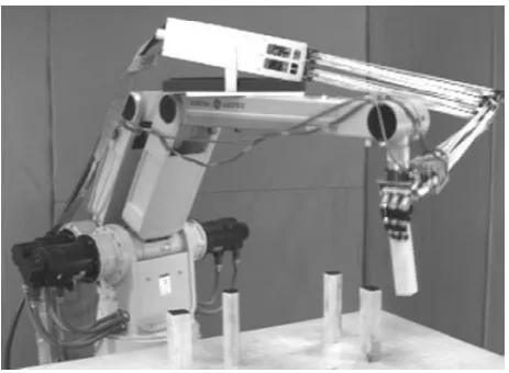
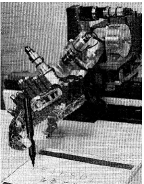
[image:31.595.247.393.395.581.2]This robotic hand showed that it can pick a pen and then manipulate the pen dextrously in order to make the pen in vertical position so that it can write some characters. The picking of pen was helped by an image processing system which guided the robotic system to the place and orientation of the pen.
19
2.3.7. National Taiwan University (NTU) Hand
A five finger anthropomorphic hand was developed by National Taiwan University in 1996 with seventeen degrees of freedom [18]. In contrast to previous tendon-driven robots, the NTU hand had an uncoupled configuration that allowed each finger and joint to be driven individually. Completely intrinsic design was developed by putting all the actuators, mechanical parts and sensors inside the robotic hand. The size of this hand is almost the same as human hand. Due to the small size this hand was suited for industrial as well as for rehabilitation purposes. The hand was easily mountable to the wrist of industrial arm or the casualty.
20
Figure 2.8 NTU Hand
2.3.8. DIST Hand
In 1998 University of Genova developed DIST hand [19] and [20]. The DIST-Hand was a four fingered mechanism with sixteen degrees of freedom with a high degree of dexterity. The main goal pursued during the development of the DIST-Hand was designing a small and lightweight dextrous gripper with anthropomorphic kinematics, which could be easily ported and installed even on small robot manipulators. The developers tried to develop with possible cheap off-the shelf components where available to reduce the overall cost of robotic hand.
Each finger had four joints each and each joint was able to move more than 90o
21
Figure 2.9 DIST Hand
The tendons and relative sheaths produced elastic perturbations in the position of the finger which made the control of the fingers’ motions, using position and velocity feedback directly from the motor axes, critical. To address this problem, they developed ad hoc rotation sensors mounted on each joint. Using these sensors it was possible to implement servo loops around the perturbations due to the elasticity and in part to friction. The sensor was based on the use of a solid state Hall Effect transducer. The sensor was contactless therefore it does not affect the motion of the joints. Furthermore, it had a significant immunity to noise with respect to other transducers of comparable size (e.g. micro/mini potentiometers, encoders).
22
structure. In that structure they had Medium Level Control (MLC), Low Level Control (LLC) and Very Low Level Control (VLLC). Each finger had LLC and VLLC. The VLLC directly interacted with the physical systems. Whereas the LLC provided input to VLLC in the form of joint position reference signal to drive the fingertip. The purpose of the MLC layer was to make all the fingers accomplish, in a cooperative way, an assigned common task (i.e. objects grasping or manipulation), without dealing with the dynamic and kinematic structure of the underlying robotic system. MLC also provided the cartesian position references to LLC according to the task performed. FPGA was mainly used to perform the hardware parallel processing to implement the complex algorithms requiring a number of matrix multiplications. The design and implementation of the real controller was made possible by the use of the System Generator, a tool developed by Xilinx in partnership with The Mathworks that enables designers to develop high-performance systems for Xilinx FPGAs using the popular MATLAB/Simulink environment.
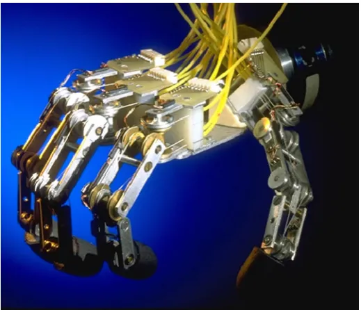
2.3.9.Robonaut Hand
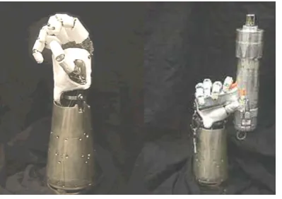
To meet the requirements for extra-vehicular activity (EVA) onboard the International Space Station (ISS), NASA developed and presented an anthropomorphic robotic hand [21]. Both power and dexterous grasp were the requirement for this space bound robot hand. As this hand was supposed to interact with the EVA crew tools, therefore it was required to perform dexterous manipulation by single or multiple fingers while grasping.
23
[image:36.595.239.439.175.316.2]inches long, contained all fourteen motors, 12 separate circuit boards, and all of the wiring for the hand. The finger drive mechanism consisted of brushless dc motor and planetary gear head.
Figure 2.10 Robonaut Hand
The hand itself was broken down into two sections; a dexterous work set which was used for manipulation, and a grasping set which allowed the hand to maintain a stable grasp while manipulating or actuating a given object. This was an essential feature for tool use. The motors were mounted outside the hand, and mechanical power was transmitted through a flexible drive train. The drive train consisted of flex shafts and leadscrew assemblies. By using this they avoided the use of tendon cables which required a complex system of pulleys.
The hand was equipped with forty-three sensors not including tactile sensing. Each joint was equipped with embedded absolute position sensors and each motor was equipped with incremental encoders. Each of the leadscrew assemblies as well as the wrist ball joint links were instrumented as load cells to provide force feedback.
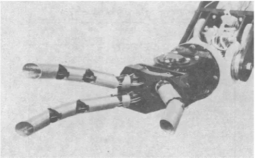
2.3.10.Distributed Touch Sensor Hand
24
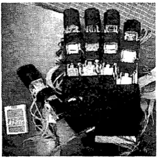
and task execution system. The hand was anthropomorphic in nature as it had five fingers but the size was twice the size of normal human hand which made it controversial to be called as anthropomorphic. Each finger had four joints; the thumb had four DOFs while the other fingers had three only. The hand surface was covered with soft rubber sheet. The distributed touch sensor was placed under the soft rubber sheet. This sensor had more than 500 measuring points on overall surface. The actuators of all finger joints were the servo unit of radio control model and all arm joints were driven by AC servo motor. The weight of this robotic hand was about 2.5kg. The servo unit of each finger joint was able to exert enough torque to handle the object within 500g and its movable angle range was around 120 degrees.
Figure 2.11 Hand with distributed touch sensor
The distributed touch sensor used had 64 lines and 16 lines of electrodes, which were placed on the both side of the pressure sensitive conductive rubber sheet. The maximum number of pressure measure points was 1024 (64 times 16). The pressure of each point was acquired in 12 bits resolution through ADC board. The whole surface was scanned within 20ms.
[image:37.595.255.418.316.478.2]161
REFERENCES
[1]. Aristotle, Di partibus animalium: 687a 7, ca. 340 BC
[2]. M. A. Farooqi, T. Tanaka, K. Nagata, Y. Ikezawa, and T. Omata, “Sensor based control for the execution of regrasping primitives on a multifingered robot,” in Proceedings of IEEE International Conference Robotics and Automation, 1999.
[3]. J. Hong, G. Lafferriere, B. Mishra, and X. Tan, “Fine manipulation with multifinger hands,” in Proceedings of IEEE International Conference Robotics and Automation, 1990, pp. 1568–1573.
[4]. A. A. Cole, P. Hsu, and S. S. Sastry, “Dynamic control of sliding by robot hands for regrasping,” in IEEE Transactions on Robotics and Automation, vol. 8, pp. 42–52, Feb. 1992.
[5]. S. Goyal, “Planar sliding of a rigid body with dry friction: Limit surfaces and dynamics of motion,” Ph.D. dissertation, Cornell Univ., Ithaca, NY, 1989.
[6]. A. Bicchi, "Hands for dexterous manipulation and robust grasping: A difficult road toward simplicity", in IEEE Transactions on Robotics and Automation, vol. 16, pp. 652 - 662, 2000.
162
[8]. H. Hashimoto, H. Ogawa, T. Umeda, M. Obama, and K. Tatsuno, “An unilateral master-slave hand system with a force-controlled slave hand,” in Proceedings of IEEE International Conference Robotics and Automation, 1995, pp. 956–961.
[9]. Emeagwali I., Marayong P., Abbott J. J., Okamura A. M., "Performance analysis of steady-hand teleoperation versus cooperative manipulation", HAPTICS '04 Proceedings, 12th International Symposium on Haptic Interfaces for Virtual Environment and Teleoperator Systems, 2004, pp. 316- 322, March 2004
[10]. Paul Michelman , Peter Allen, “Shared Autonomy in a Robot Hand Teleoperation System”, Proceedings of the 1994 Conference On Intelligent Robotics Systems, pp. 253—259, 1994
[11]. Haiying Hu, Jiawei Li, Zongwu Xie, Bin Wang, Hong Liu, Hirzinger G., "A robot arm/hand teleoperation system with telepresence and shared control" Proceedings 2005 IEEE/ASME International Conference on Advanced Intelligent Mechatronics, pp.1312-1317, July 2005
[12]. Heinrich Arnold Ernst, MH-1 A Computer- Operated Mechanical Hand, D.Sc. Thesis 1961.
[13]. Shigeo Hirose, Yoji Umetani, The development of soft gripper for the versatile robot hand, Mechanism and Machine Theory, Volume 13, Issue 3, 1978, Pages 351-359
163
[15]. T. Okada, “Object handling system for manual industry,” IEEE Transactions on Systems, Man and Cybernetics, vol. SMC-9, no. 2, 1979.
[16]. S. C. Jacobsen, J. E. Wood, D. F. Knutti, and K. B. Biggers, “The Utah-MIT dexterous hand: Work in progress,” The International Journal of Robotics Research, vol. 3, no. 4, pp. 21–50, 1984.
[17]. Hashimoto H., Ogawa H., Obama M., Umeda T., Tatuno K., Furukawa T., "Development of a multi-fingered robot hand with fingertip tactile sensors," Proceedings of the 1993 IEEE/RSJ International Conference on Intelligent Robots and Systems '93, IROS '93., vol.2, pp.875-882 26-30 Jul 1993.
[18]. Li-Ren Lin, Han-Pang Huang, "Mechanism design of a new multifingered robot hand," Proceedings of IEEE International Conference on Robotics and Automation, 1996, vol.2, no., pp.1471-1476 vol.2, 22-28 Apr 1996
[19]. Caffaz, A., Cannata, G. , "The design and development of the DIST-Hand dextrous gripper," Proceedings. 1998 IEEE International Conference on Robotics and Automation, 1998., vol.3, pp.2075-2080, 16-20 May 1998
[20]. Casalino G., Caffaz A., Cannata G., Panin G., Messucco E., "The DIST hand, an anthropomorphic, fully sensorized, dexterous gripper", IEEE Workshop Humanoids 2000, Boston, pp. 588-604, 2000.
[21]. Lovchik C. S., Diftler M. A., "The Robonaut hand: a dexterous robot hand for space," Proceedings. 1999 IEEE International Conference on Robotics and Automation, 1999, vol.2, pp.907-912, 1999
164
Electronics Society, 2000. IECON 2000. 26th Annual Confjerence of the IEEE, vol.1, pp.434-439, 2000
[23]. Butterfass J., Grebenstein M., Liu H., Hirzinger G., "DLR-Hand II: next generation of a dextrous robot hand" Proceedings 2001 IEEE International Conference on Robotics and Automation, ICRA 2001, vol.1, pp. 109- 114, 2001
[24]. Erico Guizzo, “Building a Super Robust Robot Hand”, IEEE Spectrum's robotics blog, January 25, 2011 Casalino G., Giorgi F., Turetta A., Caffaz A., "Embedded FPGA-based control of a multifingered robotic hand" Proceedings ICRA '03. IEEE International Conference on Robotics and Automation, 2003, vol.2, pp. 2786- 2791, 2003
[25]. Namiki A., Imai Y., Ishikawa M., Kaneko M., "Development of a high-speed multi-fingered hand system and its application to catching", Proceedings. 2003 IEEE/RSJ International Conference on Intelligent Robots and Systems, 2003. (IROS 2003), vol.3, pp. 2666- 2671, 2003
[26]. Xuan-Thu Le, Wn-Goo Kim, Byong-Chang Kim, Sung-Hyun Han, Jong-Guk Ann, Young-Ho Ha, "Design of a Flexible Multifingered Robotics Hand with 12 D. O. F and Its Control Applications," SICE-ICASE, 2006. International Joint Conference on Control, Automation and Systems, pp.3461-3465, 2006
165
[28]. L.Q. Tan, S.Q. Xie, I.C. Lin, T. Lin, "Development of a Multifingered Robotic Hand", ICIA '09. International Conference on Information and Automation, 2009, pp.1541-1545, June 2009
[29]. Takeuchi Hiroki, Watanabe Tetsuyou, "Development of a Multi-fingered Robot Hand with Softness-changeable Skin Mechanism," 2010 41st International Symposium on Robotics (ISR), and 2010 6th German Conference on Robotics (ROBOTIK) , pp.1-7, June 2010
[30]. Chalon Maxime, Wedler Armin, Baumann Andreas, Bertleff Wieland, Beyer Alexander, Butterfass Joerg, Grebenstein Markus, Gruber Robin, Hacker Franz, Kraemer Erich, Landzettel Klaus, Maier Maximilian, Sedlmayr Hans-Juergen, Seitz Nikolaus, Wappler Fabian, Willberg Bertram, Wimboeck Thomas, Hirzinger Gerd, Didot Frederic, "Dexhand: A Space qualified multi-fingered robotic hand", 2011 IEEE International Conference on Robotics and Automation (ICRA), pp.2204-2210, May 2011
[31]. Shadow Dexterous Hand C6M, Technical Specification, Current Release August 2009. http://www.shadowrobot.com/hand/techspec.shtml
[32]. Frank Daerden and Dirk Lefeber, " Pneumatic Artificial Muscles: Actuators For Robotics And Automation," European journal of Mechanical and Environmental Engineering, vol.47, pp.10-21, 2000.
[33]. J. Denavit and R.S. Hartenberg, 1955, "A kinematic notation for lower-pair mechanisms based on matrices." Trans ASME J. Appl. Mech, 23:215–221.
166
[35]. Dirman Hanafi, Amran Mohd Zaid, Ignatius Agung Wibowo, Mohd Najib Ribuan, Mohd Fauzi Zakaria, Sumaiya Mashori, Mohd Rizal Arshad, “Development of Multi-Finger Robot Hand Model for Dynamic Analysis”, 2010 International conference on Manufacturing and Engineering Systems.
[36]. Mathew H. M. Lee, Alex Moroz, "Normal Values for Range of Motion of Joints", The Merck Manual Online, Merck Sharp & Dohme Corp., a subsidiary of Merck & Co., Inc., Whitehouse Station, N.J., U.S.A., February 2009.
[37]. Yuichi Kurita, Yasuhiro Ono, Atsutoshi Ikeda, Tsukasa Ogasawara, “Human-sized anthropomorphic robot hand with detachable mechanism at the wrist”, Mechanism and Machine Theory, Volume 46, Issue 1, January 2011
[38]. Seunghoon Shin, Sangchul Han, Kunwook Lee, Hyungpil Moon, Hyouk Ryeol Choi, Ja Choon Koo, "A design framework for dexterous robotic hand", 2011 8th International Conference on Ubiquitous Robots and Ambient Intelligence (URAI), Incheon, Korea, November 2011
[39]. Shinji Matsubara, Shingo Okamoto and Jae Hoon Lee, “Prosthetic Hand Using Shape Memory Alloy Type Artificial Muscle”, International Multi Conference of Engineers and Computer Scientists, Hong Kong, March 2012.
[40]. Nozaki, Takahiro, Yusuke Suzuki, and Kouhei Ohnishi. “Transmission of Force Sensations by Hand of Multi-DOF Master-Slave Robot Using Tendon-Driven Mechanism.” Ieej Transactions On Industry Applications (2011)
[41]. Akihiro Yamaguchi, Kenjiro Takemura, Shinichi Yokota, Kazuya Edamura, “A robot hand using electro-conjugate fluid”, Sensors and Actuators A: Physical, Volume 170, Issues 1–2, November 2011.
167
and Japan using humanoid robot hand/arm”. Proceedings of the 6th international conference on Human-robot interaction (HRI '11), 2011, ACM, New York, USA.
[43]. Dongmok Kim, Jongwon Kim, Kyouhee Lee, Cheolgyu Park, Jinsuk Song, Deuksoo Kang, “Excavator tele-operation system using a human arm”, Automation in Construction, Volume 18, Issue 2, March 2009.
[44]. Lewis B., Sukthankar G., "Two hands are better than one: Assisting users with multi-robot manipulation tasks", IEEE/RSJ International Conference on Intelligent Robots and Systems (IROS), 2011, pp.2590-2595, Sept. 2011.