A CFD Preliminary Study: Pressure Losses and Flow Structure in Turning
Diffuser by means of Installing Turning Baffles
Eugene L.Z.P 1,*, Normayati Nordin1, Safiah Othman1, Vijay R.Raghavan2
1
Universiti Tun Hussein Onn Malaysia, 86400 Parit Raja, Johor.
2
Universiti Teknologi Petronas, 31750 Tronoh, Perak.
*E-mail: [email protected]
Abstract:
In this study, the main objective is to preliminary investigate the mechanism of flow structure and pressure losses reduction in turning diffusers before and after installing turning baffles. For this investigation two baffles were installed in the turning diffuser. CFD code FLUENT was used to simulate and obtain the results. From the resulting outputs, before baffles were installed, there was a flow separation at the inner wall of the turning diffuser and the velocity distribution was not evenly distributed. After the installation of baffles, there was an improvement in reducing flow separation at the inner wall of diffuser and the velocity was evenly more distributed. However, there was a significant pressure loss while having baffles in the system as much as 2.5.
Keywords: CFD preliminary study; flow structure; pressure losses; turning diffuser; baffles
1. Introduction
A diffuser is a mechanical device that is designed to control the character of fluid at the entrance of a thermodynamic open system. It could be in the shape of round, rectangular and square. Diffusers are commonly used in heating, ventilation, and air-conditioning systems as a part of room air distribution subsystem, and serve several purposes as following, to deliver conditioned and ventilated air evenly, to distribute the flow of air in the desired directions, to create low-velocity air movement in the occupied room and to enhance mixing of room air into the primary air being discharged.
In this study, the phenomenon of flow in a turning diffuser was investigated. Basically, turning diffuser is a bending duct which diffuses at once. Turning diffuser is often used particularly when the space to install
the whole system provided is limited. However, the flow in a turning diffuser is more complex to be judged, thus susceptible to great losses.
In this study, turning baffles [1, 2] were used in order to increase the performance of the system in terms of pressure losses reduction and flow structure. The main idea of installing baffles is to guide fluid flow in a proper pathway.
2. Literature Review
stability, the divergence angle for a pyramidal diffuser should be smaller than 10°. The optimum divergence angles suggested were between 8° and 10° with a fixed spacer length, according to the minimum pressure loss prediction using CFD shows in Table 1.
Table 1: Effect of divergence angle on the predicted diffuser loss coefficient (diffuser length = 0.679). (Gan & Riffat, 1996)
Angle
(degrees)
Area
ratio
4 1.34 0.37 0.63
6 1.53 0.45 0.55
8 1.73 0.48 0.52
10 1.95 0.48 0.52
12 2.18 0.46 0.54
15 2.55 0.43 0.57
20 3.23 0.37 0.63
30 4.90 0.30 0.70
40 7.00 0.25 0.75
In order to reduce flow maldistribution, guide vanes can be installed in the diffuser. An investigation on 180° rectangular turning rapid diffuser with total angle of divergence equal to 25° had been done. Two baffles were also installed in turning rapid diffuser. With installation of two guide vanes in turning rapid diffuser, flow produce is quite uniform [2]. Besides that, the invention of turning vanes was done to minimize pressure loss at the turning or ducting area [1]. Base on previous work, research in installing helical baffle in shell-and-tube heat exchanger which is to mix the flow in heat exchanger instead of getting a uniform flow [4].
3. Methodology
3.1 Baffles design
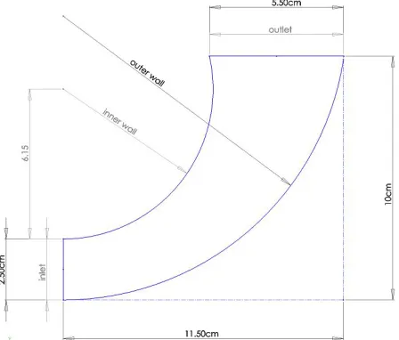
In this numerical investigation, baffles were installed in a turning diffuser to observe the flow structure and pressure recovery coefficient. The types of baffles chosen were turning baffles type and the total of baffle used was two as shows in Figure 1. The thickness of baffles was 0.2mm. In this investigation, due to insufficient of spaces at the inlet of turning diffuser and the thickness of turning baffles also affects the installation of turning baffles in a restricted area, the total of two turning baffles were installed in a turning diffuser. Turning baffles were not installed from the beginning of inlet until end of outlet as to prevent the flow separated into different sections.
3.2 Computational Approach
Figure 1 and 2 shows the schematic diagram of turning diffuser before and after installing baffles respectively. The geometries were generated using GAMBIT. CFD code FLUENT was then used to solve the 2-D governing equations for steady state fluid flow.
[image:2.612.328.552.456.647.2](b)
Figure 2: Turning diffuser with baffles
The Reynolds-Averaged Navier-Stokes (RANS) Equations Model and K-epsilon were applied to simulate the turbulent flow in the chamber. A standard discretisation scheme was used for the continuity equation. In order to reduce numerical diffusion, a second-order upwind scheme was selected for the discretisation of the momentum equations, turbulent kinetic energy equation and the turbulence dissipation rate equation. The SIMPLE algorithm was applied to solve the pressure-velocity coupling algorithms.
In this study, PC with specifications of Intel Core 2 Duo 1.80 GHz, 4.00 GB RAM was used.
3.3 Governing equations
For the simulation purpose, 3-D equations in Cartesian coordinate form have been solved numerically for a Newtonian, incompressible fluid:
Continuity Equations
(1)
Conservation of Momentum Equations
(2)
(3)
3.4 Boundary conditions
The inlet air flow was modeled as a uniform velocity with the value of 0.403m/s, while the outlet was modeled as a constant atmospheric pressure of 1.01325bar. Air was taken as the fluid domain. Baffles were defined as solid domain.
4. Results and discussions
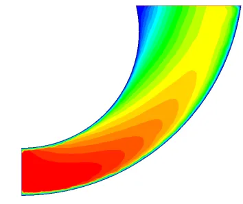
[image:3.612.347.524.499.648.2]From the resulting outputs, Figure 3 yields that for turning diffuser without baffle the fluid flow by following the path way at the lower wall of the turning diffuser. There are low velocities at the inner wall of the turning diffuser and a bit of flow separation which shown in blue colour at the outlet of the inner wall. The effect of flow separation in turning diffuser is in the form of reduction in velocity. By installing baffles, the fluid flow shows
Figure 4: Flow structure turning diffuser with baffles
an improvement (see Figure 4). The fluid follows the path provided by the turning baffles.
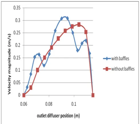
There is still separation occurs at the outlet of the inner wall but separation at that part is reduced. Flow separation also occurs at the both end of the tips of the baffles where also call the wake region. The wake is a region of flow trailing the body where the effects of the body on velocity are felt. The separated region comes to an end when the two flow streams reattach. This phenomenon was also causes by the form drag. At the outlet of turning diffuser without baffles, as shown in Figure 5, velocity increases from right to left of the turning diffuser. Whereas, for turning diffuser with baffles, velocity more symmetry at the outlet.
The total pressure for turning diffuser without baffles, as shown in Figure 6, is higher at the inlet and decreases when approaching inlet wall of turning diffuser. Meanwhile, for turning diffuser with installation of baffles, total pressure at the inlet in much more lower and total pressure at the outlet is evenly distributed. At the beginning tips of the baffles, the pressure was higher compare to the end tips of baffles due to form drag as shown in Figure 6 (b). From the mean and standard deviation shows in Table 2 and 3, it show that after installation of baffles; the velocity is more evenly distributed because of range is smaller
than the range of turning diffuser before installation of baffles.
[image:4.612.323.568.210.426.2]However, as shown in Table 4, there is a reduction in terms of pressure recovery while having baffles. Losses (K) as much as 2.5, was recorded for a turning diffuser with baffles compared to only 1.0 for a turning diffuser without baffles.
Figure 5: Velocity at outlet of turning diffuser
(b)
[image:5.612.92.264.128.300.2]Figure 6: Total pressure of turning diffuser (a) without baffle and (b) with baffles
Table 2: Velocity magnitude (m/s) before installation of turning baffles
Mean = 0.160438
Standard Deviation = 0.11125
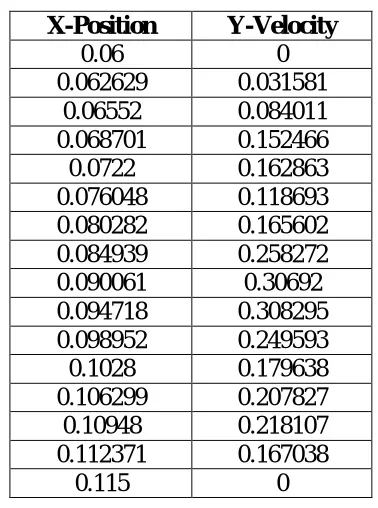
Table 3: Velocity magnitude (m/s) after installation of turning baffles
Mean = 0.163182
[image:5.612.95.279.389.564.2]Standard Deviation = 0.097457
Table 4: Comparison of Cp before and after installation of turning baffles
Pressure Recovery Coefficient
Before After
Cp 0.023 -1.464
5. Conclusion
In conclusion, the objective to preliminary investigate the mechanism of flow structure and pressure losses reduction in turning diffusers before and after installing baffles is achieved.
This work is meaningful being a kick-start of determining the potential configuration of turning diffuser before experimental works are conducted.
It can be concluded that by installation of baffles in a turning diffuser, it helps to reduce the flow separation. Indeed the turning baffles act similar to a “flow divider” which
X-Position Y-Velocity
0.06 0
0.0655 0.029152 0.071 0.099407 0.0765 0.151122 0.082 0.191247 0.0875 0.226089 0.093 0.256916 0.0985 0.275041 0.104 0.282592 0.1095 0.253254
0.115 0
X-Position Y-Velocity
0.06 0
0.062629 0.031581 0.06552 0.084011 0.068701 0.152466 0.0722 0.162863 0.076048 0.118693 0.080282 0.165602 0.084939 0.258272 0.090061 0.30692 0.094718 0.308295 0.098952 0.249593 0.1028 0.179638 0.106299 0.207827 0.10948 0.218107 0.112371 0.167038
divert some of the higher mass flow from the outer-wall region and inject it into the inner-wall region. However, the losses in a turning diffuser with baffles increase due to skin friction. Finally, turning diffuser with installation of turning baffles provides better uniform flow but for pressure losses, improvement still can be made.
It is recommended that the baffles near to the inner wall of turning diffuser should be moved near to the inlet area so that the fluid flow can evenly be distributed and flow separation at the end of tip of baffle could be reduced. In addition the second baffle that near to the outer wall should be extended longer as to evenly distribute the flow. Design the turning baffles surface that has the lowest drag coefficient to prevent friction and pressure drag.
Nomenclature
p pressure density
μ dynamic viscosity
x,y cartesian coordinates
v, velocity
pressure coefficient
pressure loss coefficient
Acknowledgement
The work reported in this paper is sponsored by Ministry of Higher Education under the Fundamental Research Grant Research (FRGS) scheme.
References
[1] MacBain, S.M. (2003). Chiller
Compressor Circuit Containing
Turning Vanes.S.Patent 6,668,580 B2.
[2] Nguyen, C.K., Ngo, T.D., Mendis, P.A. & John Cheung, C.K. (2006). A flow analysis for a turning rapid diffuser using CFD. Journal of Wind
Engineering, 108, pp. 749-752.
[3] Gan, G. & Riffat, S.B. (1996). Measurement and computational fluid dynamics prediction of diffuser pressure-loss coefficient. Applied Energy, 54 (2), pp. 181-195.
[4] Yong, G.L., He, Y.L., Li, R. & Gao, Y.F. (2008). Loss characteristics and flow rectification property of diffuser valves for micropump applications.
International Journal of Heat and Mass