www.ijsrp.org
Tracing With Real-Time Compression for an On-Chip
AHB Bus
S.Thripurna
1, G.Renuka
2, Dr. Syed Musthak Ahmed
31
(Embedded Systems, S R Engineering College, India)
2
(Embedded Systems, S R Engineering College, India)
3
(Embedded Systems, S R Engineering College, India)
ABSTRACT
:
A multiresolution AHB on-chipbus tracer named SYS-HMRBT (AHB multiresolution bus tracer) for versatile system-on-chip (SoC) debugging and monitoring. The bus tracer is capable of capturing the bus trace with different resolutions, all with efficient built-in compression mechanisms, to meet a diverse range of needs. Experiments show that the bus tracer achieves very good compression ratios of 79%–96%, depending on the selected resolution mode. The SoC has been successfully verified both in field-programmable gate array and a test chip.Index Terms
:
AHB, AMBA, compression, system-on-chip (SoC) debuggingI.
INTRODUCTION
The On-Chip bus is an important system-on-chip (SoC) infrastructure that connects major hardware components. Monitoring the on-chip bus signals is crucial to the SoC debugging and performance analysis/optimization. Unfortunately, such signals are difficult to observe since they are deeply embedded in a SoC and there are often no sufficient I/O pins to access these signals. Therefore, a straightforward approach is to embed a bus tracer in SoC to capture the bus signal trace and store the trace in an on-chip storage such as the trace memory which could then be off loaded to outside world (the trace analyser software) for analysis.
Unfortunately, the size of the bus trace grows rapidly. For ex-ample, to capture AMBA AHB 2.0 bus signals running at 200 MHz, the trace grows at 2 to 3 GB/s. Therefore, it is highly desirable to compress the trace on the fly in order to reduce the trace size. However, simply capturing/compressing bus signals is not sufficient for SoC debugging and analysis, since the de-bugging/analysis needs are versatile: some designers need all signals at cycle-level, while some others only care about the transactions. For the latter case, tracing all signals at cycle-level wastes a lot of trace memory. Thus, there must be a way to cap-ture traces at different abstraction levels based on the specific debugging/analysis need.
II.
TRACE GRANULARITY
This section first introduces the definitions of the abstraction level. Then, it discusses the application for each abstraction mode.
At the timing dimension, it has two abstraction levels, which are the cycle level and transaction level. The cycle level captures the signals at every cycle. The transaction level records the signals only when their values change (event triggering). For example, since the bus read/write control signals do not change during a successful transfer, the tracer only records this signal at the first and last cycles of that transfer. However, if the signal changes its value cycle-by-cycle, the transaction-level trace is similar to the cycle-level trace.
A) Mode FC:
Thetracer traces all bus signals cycle-by-cycle so that designers can observe the most detailed bus activities. This mode is very useful to diagnose the cause of error by looking at the detail signals. However, since the traced data size of this mode is huge, the trace depth is the shortest among the five modes. Fortunately, it is acceptable since designers using the cycle-level mode trace only focus on a short critical period.
B) Mode FT:
The tracer traces all signals only when their values are changed. In other words, this mode traces the un-timed data transaction on the bus. Comparing to Mode FC, the timing granularity is abstracted. It is useful when designers want to skim the behaviours of all signals instead of looking at them cycle-by-cycle. Another benefit of this mode is that the space can be saved without losing meaningful information. Thus, the trace depth increases.
www.ijsrp.org
The tracer uses the BSM, such as NORMAL, IDLE, ERROR, and so on, to represent bus transfer activities in cycle accurate level. Comparing to Mode FC, although this mode still captures the signals cycle-by-cycle, the signal gran-ularity is abstracted. Thus, designers can observe the bus hand-shaking states without analysing the detail signals. The benefit is that designers can still observe bus states cycle-by-cycle to analyse the system performance.
D) Mode BT:
The tracer uses bus state to represent bus transfer activities in transaction level. The traced data is abstracted in both timing level and signal level; it is a combination of Mode BC and Mode BT. In this mode, designers can easily understand the bus transactions without analysing the signals at cycle level.
E) Mode MT:
The tracer only records the master behaviours, such as read, write, or burst transfer. It is the highest abstraction level. This feature is very suitable for analysing the masters’ transactions. The major difference compared with Mode BT is that this mode does not record the transfer handshaking activities and does not capture signals when the bus state is IDLE, WAIT, and BUSY. Thus, designers can focus on only the masters’ transactions
III.
BUS TRACER ARCHITECTURE
[image:2.595.108.505.337.564.2]This section presents the architecture of our bus tracer. We first provide an overview of the architecture for the post-T trace. We then discuss the three major compression methods in this architecture.
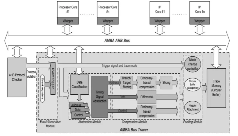
Figure 1:Bus Tracer Block Diagram
A) POST-TRACERARCHITECTUREOVERVIEW:
It mainly contains four parts: Event Generation Module, Abstraction Module, Compression Modules, and Packing Module.
The Event Generation Module controls the start/stop time, the trace mode, and the trace depth of traces. This information is sent to the following modules. Based on the trace mode, the Abstraction Module abstracts the signals in both timing dimension and signal dimension. The abstracted data are further compressed by the Compression Module to reduce the data size. Finally, the compressed results are packed with proper headers and written to the trace memory by the Packing Module.The Event Generation Module decides the starting and stopping of a trace and its trace mode. The module has configurable event registers which specify the triggering events on the bus and a corresponding matching circuit to compare the bus activity with the events specified in the event registers. Optionally, this module can also accept events from external modules.
www.ijsrp.org The compression module is to reduce the trace size. It accepts the signals from the abstraction module is pipelined to increase the performance.
i. Program Address Compression:
[image:3.595.185.370.146.282.2]
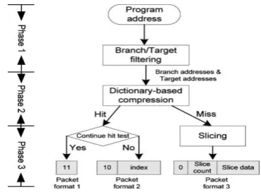
We divide the program address compression into three phases for the spatial locality and the temporal locality. Fig. 2 shows the compression flow. There are three approaches: branch/target filter, dictionary-based compression, and slicing.
Figure 2: Program Address Compression Flow And Trace Format
ii. Branch/Target Filtering:
This technique aims at thespatial locality of the program address. Spatial locality exists since the program addresses are sequential mostly. Software programs (in assembly level) are composed by a number of basic blocks and the instructions in each basic block are sequential. Because of these characteristics, Branch/target filtering can records only the first instruction’s address (Target) and the last instruction’s address (Branch) of a basic block. The rest of the instructions are filtered since they are sequential and predictable.
iii. Dictionary-Based Compression:
To further reduce thesize, we take the advantage of the temporal locality. Temporal locality exists since the basic blocks repeat frequently (loop structure), which implies the branch and target addresses after Phase 1 repeat frequently. Therefore, we can use the dictionary based compression. The idea is to map the data to a table keeping frequently appeared data, and record the table index instead of the data to reduce size. Fig. 11 shows the hardware architecture. The dictionary keeps the frequently appeared branch/target addresses. To keep the hardware cost reasonable, the proposed dictionary is implemented with a CAM-based FIFO. When it is full, the new address will replace the address at the first entry of FIFO
iv. Slicing:
The miss address can also be compressedwith the Slicing approach. Because of the spatial locality, the basic blocks are often near each other, which means the high-order bits of branch/target addresses nearly have no change. Therefore, the concept of the Slicing is to reduce the data size by recording only the different digits of two consecutive miss addresses. To implement this concept in hardware, the address is partitioned into several slices of a equal size. The comparison between two consecutive miss addresses is at the slice level.
v. Data Address/Value Compression:
Data address and datavalue tend to be irregular and random. Therefore, there is no effective compression approach for data address/value. Considering using minimal hardware resources to achieve a good compression ratio, we use a differential approach based on the sub-traction.
vi. Control Signal Compression:
www.ijsrp.org transfer behaviours. Second, control signals change infrequently in a transaction.
IV.
EXPERIMENTAL RESULTS
[image:4.595.169.382.113.228.2]The specification of the implemented SYS-HMRBT bus tracer is shown in Table
Table I:Specification Of The Implemented Sys-HMRBT Bus Tracer
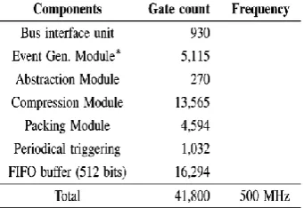
It has been implemented at C, RTL, FPGA, and chip levels. The synthesis result with TSMC 0.13- technology is shown in Table II
Table II:Syntheses Results Under Tsmc 0.13- M Technology
The bus tracer costs only about 41 K gates, which is relatively small in a typical SoC. The largest component is the FIFO buffer in the packing module. The second one is the compression module. The cost to support both the pre-T and post-T capabilities (periodical triggering module) is only 1032 gates. The major component of the event generation module is the event register, which is roughly 1500 gates per register. The implementation in this paper has two event registers. More registers can be added if necessary. Compared with our previous work the gate count is reduced by 31%. The reason is that this paper optimizes the ping-pong architecture by sharing most of the data path instead of duplicating all the hardware components. As for the circuit speed, the bus tracer is capable of running at 500 MHz, which is sufficient for most SoC’s with a synthesis approach under 0.13- m technology. If a faster clock speed is necessary, our bus tracer could be easily partitioned into more pipeline stages due to its streamlined compression/packing processing flow.
CONCLUSION
We have presented an on-chip bus tracer SYS-HMRBT for the development, integration, debugging, monitoring, and tuning of AHB-based SoC’s. It is attached to the on-chip AHB bus and is capable of capturing and compressing in real time the bus traces with five modes of resolution. These modes could be dynamically switched while tracing. The bus tracer also supports both directions of traces: pre-T trace (trace before the triggering event) and post-T trace (trace after the triggering event). In addition, a graphical user interface, running on a host PC, has been developed to configure the bus tracer and analyse the captured traces. With the aforementioned features, SYS-HMRBT supports a diverse range of design/de-bugging/monitoring activities, including module development, chip integration, hardware/software integration and debugging, system behaviour monitoring, system performance/power analysis and optimization, etc. The users are allowed to trade off between trace granularity and trace depth in order to make the most use of the on-chip trace memory or I/O pins.
.
REFERENCES
[1]
ARM Ltd., San Jose, CA, “AMBA Specification (REV 2.0) ARM IHI0011A,” 1999. [image:4.595.201.372.277.394.2]www.ijsrp.org
[3]
ARM Ltd., San Jose, CA, “ARM. AMBA AHB Trace Macrocell (HTM) technical reference manual ARM DDI 0328D,” 2007.[4]
First Silicon Solutions (FS2) Inc., Sunnyvale, CA, “AMBA navigator spec sheet,” 2005.[5]
J. Gaisler, E. Catovic, M. Isomaki, K. Glembo, and S. Habinc, “GRLIB IP core user’s manual, gaisler research,” 2009.[6]
Infineon Technologies, Milipitas, CA, “TC1775 TriCore users manual system units,” 2001.[7]
ARM Ltd., San Jose, CA, “Embedded trace macrocell architecture specification,” 2006.[8]
E. Rotenberg, S. Bennett, and J. E. Smith, “A trace cache microar-chitecture and evaluation,” IEEE Trans. Comput., vol. 48, no. 1, pp. 111– 120, Feb. 1999.[9]
A. B. T. Hopkins and K. D. Mcdonald-Maier, “Debug support strategy for systems-on-chips with multiple processor cores,” IEEE Trans. Comput., vol. 55, no. 1, pp. 174–184, Feb. 2006.[10]
B. Tabara and K. Hashmi, “Transaction-level modeling and debug of SoCs,” presented at the IP SoC Conf., France, 2004.[11]
Infineon Technologies, Milipitas, CA, “TC1775 TriCore users manual system units”Authors Biography
S.Thripurna was born in Warangal district, A.P, India. She received B-Tech in Electronics and Communication Engineering from Balaji Institute of Technology and Sciences, Warangal (dist), A.P, India. Perusing M. Tech in Embedded Systems at SR Engineering College, Warangal, A.P, India.
E-Mail: [email protected]
G.RENUKAreceived M-Tech from KITS Engineering College, Warangal, A.P, India. She is working as Assistant Professor for dept of Electronics and Communication Engineering, SR Engineering College, Warangal, A.P, India. She has 8 years of teaching experience in reputed engineering colleges. Her research interests include VLSI and Embedded Systems.
E-Mail: [email protected]
Dr.SyedMusthaqAhmed(Prof) completed B.E(Electronics) and M.E(Electronics) from Bangalore university(Karnataka) and
PhD from Vinayaka Mission’s University (Tamil Nadu).He has 28 years of teaching experience in reputed engineering colleges and he is presently working as Prof &HOD(ECE), SR Engineering college, warangal, A.P. He is Doctoral committee member as well as Indian examiner in reputed universities. He is a member of various professional societies viz SMIEE, MISSS FITEE, MISTE, MIAENG, MIATM. He has various publications in National & International Journal/Conferences.
E-Mail: [email protected]
S.Thripurna was born in Warangal district, A.P, India. She received B-Tech in Electronics and Communication Engineering from Balaji Institute of Technology and Sciences, Warangal (dist), A.P, India. Perusing M. Tech in Embedded Systems at SR Engineering College, Warangal, A.P, India.
E-Mail: [email protected]