industries are emergent in a fastest rate. Plastic injection molding begins with mould making and in manufacturing of complex shapes; the optimum gate location is one of the most important criterions in mould design. Mould Flow analysis is a powerful simulation tool to optimize the gate location and to predict the Production time required at the lowest possible cost.
Optimization of sequence occasion, keep away from scrap and manual interface plays a vital role in manufacturing of plastic parts to improve the productivity of the process and at the time it should not affect the quality of the final product. This paper describes the influence of gate location and size through a repeated number of analyses which is carried out by plastic flow advisor software to reduce fill time, scrap and automatic degating. The process parameters like fill time, shrinkage, weld lines, pressure drop, and air traps are analyzed by simulation in successive trials. Experimental verification has been done with new optimized gate location with designed mould in Injection molding machine. The results showed an improvement in fill time from 1.58 sec to 1.22 sec with increase in injection Pressure by 80 MPa. Shrinkage and air traps were reduced minimizing trouble shooting defeats.
Index Terms- Plastic Injection mould, Mould Flow Plastic Advisor (MPA), Feeding system, Submarine gate, Injection Pressure
I. INTRODUCTION
lastic is a material that can produce many shapes that can be used by human in routine life. All of plastic products are produce from various type of operation or process. All of product Produces with different type of plastic material depend to needed. Plastics are divided into two distinct groups’ thermoplastics and thermo sets. Plastics can be molded into various forms and hardened for commercial use. Plastic is perfect for this modern age. It is light, strong, easily molded and durable. Although plastics are thought of as a modem invention, there have always been “natural polymers" such as amber, tortoise shells and animal horns. These materials behaved very much like
way manufactured plastics are currently applied.
The typical process cycle time in injection molding machine varies from several seconds to tens of seconds depending on the part weight, part thickness, material properties and the machine settings specific to a given process. Process control of injection molding has a direct impact on the final part quality and the economics of the process. In the injection molding processes, gate location is very important design parameter with is in the relation with polymer capability, part shape and dimension, mould structure and mould condition, the selection of gate location influences the manner in which plastic flows in to the mould cavity. In order to set the processing parameters, conventional trial and error method is followed which is many times inadequate and unpractical for complex parts. The placement of a gate in an injection mould is one of the most important variables in mould design and the quality of the product is greatly affected by the gate location. Thus the objective of this paper is to design the feeding system that ensures the better part quality to design and manufacturing the injection mould for lower washer of a bearing.
II. PART DETAILS
Material: PBT-GF 20%
Common Name: Polybutylene Terephthalate
Abbreviation: PBT.Also known as PTMT (Polytetramethylene Terephthalate)
Systematic Chemical Name: Poly (Oxytetramethylene – Oxyterephthalate)
Color: BLACK Part weight: 25grams
General wall thickness: 1.9mm
Polybutylene Terephthalate is one of the toughest engineering plastic. It is a semi crystalline resin and has excellent chemical resistance, mechanical strength, electrical properties (high dielectric and insulation resistance) and heat resistance, all of which are stable over a broad range of environmental conditions. It has very low moisture absorption.
Fig. 1.CAD model of Bobbin.
III. PROBLEM STATEMENT
A parameter setting and feeding system such as gate, runner and sprue inside the plastic injection mould are located by mould makers using trial and error method. At this situation, people that have a lot of experience in injection molding process who capable to decide the size and location of feeding system especially in two plate mould. The problems occur when this person cannot perform the job with good method and needed to take much time to think and make an experiment. Simulation software is the new technology that can examine the behaviors of plastic flow inside the cavity mould. It can decide the better method to select the best design for feeding system like runner, sprue, and gate and process parameter. The size of gate, runner and sprue is importance thing to consider for producing good quality plastic product. It can give effect to product if the unsuitable type or sizes are used. There are many type of simulation software now that can make work more easy and accurate.
The Plastic adviser Software is one of software used to ensure the best choice location of feeding system and size of gate, runner and sprue. It's one of the most advanced tools ever devised for the plastic injection molding engineer. More precisely, it's a computer generated 3D simulation that models the flow of resin material into a single or multi-cavity mould. With the aid of mould flow analysis, engineers can obtain statistical data of the molding process before the mould is actually constructed. The object is to optimize the fill process of a mould and the integrity of the molded part. The data provided during the analysis helps the engineer select the optimum
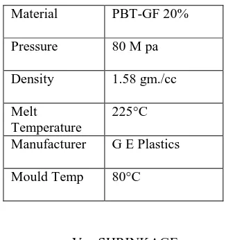
advisor for component suggests the best gate location for the selected material properties. The simulation rates the model areas for their suitability for injection location where the worst position is classified as least suitability for an injection location in red color and the best position is classified as the most suitable in blue color. The input for plastic advisor software is given in the Table 1 and the gate location examines these five aspects of the part.
1. Process ability. 2. Minimum Pressure.
3. Geometric Resistance. 4. Thickness.
[image:2.612.363.526.420.593.2]5. Flow resistance areas
Table: 1 Input Details for plastic Advisor
Material PBT-GF 20%
Pressure 80 M pa
Density 1.58 gm./cc
Melt Temperature
225°C
Manufacturer G E Plastics
Mould Temp 80°C
Fig.2. Best gate location Fig.3.Part shrinkage
VI. MOULD FLOW ANALYSIS
It is 3D solid-based plastic flow simulation that allows plastics part to determine the manufacturing of their parts during the preliminary design and avoid potential mould-filling problems such as sink marks, short shots, weld lines and air traps. It optimizes the part wall thickness to achieve uniform filling patterns, lowest part cost and minimum cycle time. 6.1. Plastic Advisor in Pro-E: Plastic advisor simulates mould filling for injection molded plastic parts and it enables engineers to design for manufacturability insight-insight that can significantly reduce late-cycle design changes and mould reengineering costs
Benefits :To creates web reports within pro-E browser, locating best optimal injection point for reducing cycle time and improve part appearance, it access library of common plastic materials and automatically select from typical injection molding machine parameters and also identify potential mould-filling problems.
VII. PLASTIC FLOW ANALYSIS
It gives the overview of the model’s analysis and the flow path of the plastic actual in the mould. 7.1. Full Time: It shows the time filing of the complete part, which displays in a range of colors from red to indicate the first region to fill, and to blue to indicate the last region to fill. A short shot is one of the parts of the model that did not fill, and will be displayed as translucent.
7.2. Confidence of Fill: It displays the probability of a region within the cavity filling with plastic at conventional injection molding conditions. It shows the figure that confidences of fill of complete part are high.
7.3. Injection Pressure The injection pressure result is a contour plot of the pressure distribution throughout the cavity at the end of filling.
7.4. Pressure Drop: It shows the pressure required to flow the material to each and every point in the cavity.
7.4 Flow Front Temperature. It uses a range of colors to indicate the region of lowest temperature (colored blue) through to the region highest temperature (colored red).The colored shows the material temperature at each point as that point was filled.
VIII. MOLD FLOW RESULT
The mould flow Simulation is done repeatedly and best three trials are show and the possible is selected for manufacturing based on fill time and air traps.
8.1. FIRST TRAIL:
Fig.4. a) Fill time b) Pressure drop
c) Air traps d) Weld lines
8.2. SECOND TRAIL:
Feeding system is redesigned and simulated with fan Gate, second trail shown in Fig5, where the part fills in 1.58 sec with pressure of 68 Mpa where air traps and sink marks are maximum, which leads defects in the component and more over ejection is quite difficult and more over there will be improper filling of material at rounded part. So this is not best, further it need best gate.
c) Air traps d) Weld line
8.3. Third Trail:
Since the results obtained in second trail are not satisfactory, feeding system is redesigned and simulated with single sub marine Gates of 1.2 mm diameter and runner width of 6mm shown in Fig 6, where the part fills in 2.18 sec with pressure of 80 Mpa where air traps are less, but weld line are marginally high. Since the results were enhanced than the previous trail, but over all cycle time is mush so, there is a scope for further optimizing the gate size.
c) Air traps d) Weld line
8.4. Fourth Trail:
Results obtained from third trail can be further optimized by changing only the gate size and simulated with 1.6 mm diameter shown in Fig 7, where the part fills in 1.45 sec with pressure of 80 Mpa, the pressure is kept same compared to previous, it is manageable. Even though the air traps are more, it can be minimized with air vents in cavity insert during manufacturing.
c) Air traps d) Weld line
IX. CONCLUSIONS
The MPA simulation analysis for the optimum gate location was performed by taking a comparison of different gate locations and from the comparative analysis, the fourth gate location was found to be the optimum one. This simulation is quite important in industries to reduce the defects arising in the products due to improper gating system. This gave satisfactory results and the
same was confirmed from analysis such as injection pressure, fill time, flow front temperature, quality of fill, weld line, air traps etc. The results indicated that the injection molded components could be manufactured with minimum molding defects.
From the four trails in the Table 2, even though pressure increases, it is well within the safe range and fill time comes down which will increase the production rate.
Table: 2. Result comparison
1st trail 2nd trail 3rd trail 4th trail
Type of gate Direct sprue Fan gate Sub marine (Dia.1.2mm)
Sub marine (Dia.1.6mm)
Fill time 1.09 sec. 1.58 sec 1.2 sec. 1.45 sec.
Pressure 52 68 80 80
Temp.flow 240C 248C 241C 241C
Air traps More More More Acceptable
Weld lines More More More Acceptable
Quality of part Poor Poor Satisfactory Good
REFERENCES
[1] RECENT METHODS FOR OPTIMIZATION OF PLASTIC INJECTION MOLDING PROCESS. (Vol. 2(9), 2010,) M. I. Khan, Prof. Harbinder Singh, Professor and Director, Bundel khand Institute of Engineering and Technology, Jhansi, India
[2] Analysis of Plastic Flow in Two Plate Multi Cavity Injection Mould for Plastic Component for Pump Seal BY Jagannatha Rao M B, Dr. Ramni
[3] APPLICATION OF COMPUTER SIMULATION FOR FINDING OPTIMUM GATE LOCATION IN PLASTIC INJECTION MOULDING PROCESS (IJAERS/Vol. I/ Issue II/January-March, 2012)