Intelligent Mobile Robot using Simplorer Simulator
Karim Jaber Chokri Abdelmoula Ahmed Fakfah Rafik Neji
LETI Research METS Research LETI Research LETI Research Laboratory, ENIS Group, ENIS Laboratory, ENIS Laboratory, ENISABSTRACT
This work describes the design and development of intelligent algorithm applied to a newly designed mobile robot type-vehicle to control actions in autonomous navigation. A novel approach has been developed and optimized to achieve several tasks in a dynamic environment. This control algorithm combine‟s different sensory information and provides command to reach the true position. The system was described in the VHDL-AMS language. Simulation results are presented and implemented with VHDL-AMS on an FPGA development card type cyclone II. All simulations are compared with a designed algorithm using all resource values.
Keywords
Mobile Robot, FPGA, Autonomous navigation, VHDL AMS.
1.
INTRODUCTION
Adaptations, robustness, and tolerance have opened their application to various fields of engineering and robot systems. Real-time applications are feasible only if low-cost high-speed computation is made viable. Implementation of classical real time algorithm can be accomplished using either analog or digital hardware. Digital implementation presents the advantage that it combines a higher accuracy, a good repeatability, and best sensitivity. On the other hand, analog systems are difficult to be designed.
Field-Programmable Gate Array (FPGA)- offer reconfigurability by the user. FPGA is the most suitable hardware for hardware implementation as it preserves the parallel architecture and can be reconfigured by the user.
This work intends to implement in a FPGA cyclone II real time classical algorithm related to the autonomous navigation to solve maneuvering operations in dynamic environment.
Designing a control algorithm requires the installation of many sensors and actuators according to their task. Obstacle avoidance is requirement for any mobile robot. Some robots use single sensing device to detect the object. But some other robots use multiple sensing devices. In this work, infrared sensor are chosen, as they preserve, most suitable ones for obstacle avoidance, their low cost and ranging capability.
Infra Red system consists of the Sharp GP2D12 distance measuring sensor. The GP2D12 is a compact, self-contained IR ranging system incorporating an IR transmitter, receiver, optics, filter, detection, and amplification circuitry. The unit is highly resistant to ambient light and nearly impervious to variations in the surface reflectivity of the detected object [1].
It is necessary to test the navigation algorithm in robots and simulated before testing on real robots and real-world environments. Shen et al used a Matlab-based simulator for algorithm development of 2D indoor robot navigation [2].
The remainder of this paper is organized as follows. After reviewing the literature related to the mobile robot navigation,
a general structure of the new designed mobile robot and the presentation of the embedded system are described in Section II. In section III the direct adaptive control design for path tracking control was presented to attend robot description in Simplorer environment. Simulations result with VHDL-AMS of the autonomous navigation and the comparison of results with an algorithm for obstacle avoidance missions are presented in section IV. The last section of the paper concludes different achieved works with future studies.
2.
SYSTEM OVERVIEW
This mobile robot is designed to explore in the environment by detecting obstacles and avoiding collision base on the distance measurement information obtained from the infrared sensors. This robot system is obstacle avoiding robot using infrared sensors.
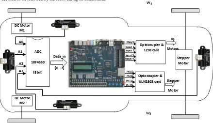
Our hardware is composed of two elements (analog and digital). The first component (microcontroller) is exploited for the capture of any analog information‟s issued for the four infrared sensors installed on the chassis of the mobile robot to be converted into numerical information‟s. The second one (FPGA) is used to command actuators (DC motors M1, M2 and the stepper motor M3).
In this system four infrared sensors are used for left, right and front. The infrared sensors, used for obstacle avoidance, are connected to the processor via analog ports. The input signal is received from sensor circuit and PIC is operated according to the received sensor‟s signal.
The reason to choose IR sensors as Obstacle detected device is that to determine the range of object and by this data, to control the Obstacles avoiding process. In this research, by using its effective rating, GP2D12 analog IR sensor is used. Analog to Digital Converting (ADC) process is done in PIC (18F4550) [3-4].
The different tasks of planning and obstacle detection by the proprioceptive sensors in the proposed platform are converted into data that are processed by the FPGA to activate the actuators without disruption during other decisions. The developed system allows the integration of multi-task operations for navigation in unknown environments [5].
The robot navigates in an unfamiliar environment containing fixed or movable barriers environment while detecting the distances that separate the robot platform from barriers. The decision to change direction (right or left) depends on the distance that separates the platform of the detected obstacle. This concept is characterized by sequential decisions for the control of actuators that obey the orders and instructions of the control algorithm. In fact, to take into account the robot inherent instability in a classical environment (moving objects, person‟s unforeseen obstacles), the adapted system is assisted by a control algorithm of obstacles avoidance. This algorithm generates a protection zone on all the robot peripherals through an infrared proximity belt (on the right, on
the left, in the front and the back) to allow the detection of the finest objects. Indeed, the data from the infrared sensors are analyzed to extract the information characterizing the fixed and mobile obstacles and the activity of persons in the same environment. Any information is then used to build the mode of decision to be followed by the robot during its autonomous
[image:2.595.61.500.144.398.2]navigation. The Figure 1 shows the overall flow of designing the system
Figure 1. The architecture of the FPGA-based motion control mobile robot
The navigation control approach applies the control algorithm for detecting an obstacle and veering to avoid a collision without making any stops. When the robot detects an obstacle on its front, it measures the distances on its right and left, resumes its motion and veers at an angle of
to the left or to the right, depending on the longest measured distance from the detected obstacles on its left or right. The design and the development of an intelligent algorithm control were described with VHDL-AMS to be implemented on the FPGA cyclone II processing platform. An original configuration was adopted consisting in interfacing a microcontroller with an FPGA circuit.In this study, FPGA is merely used to realize the hardware part of the overall control system, due its lower resource consumption when compared to parallel processing circuits. To solve the problem of auto navigation of a mobile robot in an unstructured environment, some comparators and registers are proposed to model the VHDL-AMS algorithm. The VHDL-AMS environment is adopted to describe simulations results of all configurations models to improve the capability of the robot to navigate in real time.
To make the most of advantages, a motion control for collision-free auto navigation in an unknown environment based on a FPGA card was tried on the newly physical structure of mobile robot and developed in this study. The position of all components is clearly indicated in Figure 1.
3.
KNIMATIC AND DYNAMIC MODEL
This work is developed for a vehicle -type mobile robot [6, 7]. The kinematic model takes the velocities of the steering angles and the linear velocity of the robot and transforms it into the generalized coordinate vector. The dynamic model
transforms the torques given to it into rotational acceleration of the steering wheels and linear acceleration of the frame [8]. The rear wheels are fixed and the front ones are the steering wheels which are responsible for direction change. The movement of the robot is controlled by the steering angle φ of the front wheels. The kinematics modeling of the robot in the environment is shown in Fig. 2.
The frame R (O, X, Y) is related to space navigation. Point M (XM,YM ) is located at the middle of the two front wheels θ is
the angle of orientation relative to the X axis.
Figure 2. Kinematics modeling of the mobile robot
The motion of the robot in the R frame is described by:
dX
M
v
cos( )
dY
M
v
sin( )
vsin( )
L
Where the velocity v is constant and equal 0.2 m/s. φ is the steering angle and L the distance between front and rear wheels axis. By the discretization of these equations using the Euler method, the kinematics model becomes:
ADC
18F4550
(8 bit)
Stepper Motor DC Motor
M1
DC Motor M2 A0
A1
A2
A3
Data_in
[0…7]
Optocoupler & L298 card
(DAC)
Optocoupler & ULN2803 card
(DAC)
DC
Motors
Stepper
Motor
ENA/B Input 1 Input 2 Input 3 Input 4
Ph(3) Ph(2) Ph(1) Ph(0)
w
2w
1w
3w
2
1
cos
M M
X
k
X
k
h v
k
1
sin
M M
Y
k
Y
k
h v
k
sin( )1 .v
k k h
L
Where h is the sampling step.
4.
VHDL-AMS MODELING LANGUAGE
VHDL-AMS (VHDL Language with analog and mixed-signal extensions) is used for specifying analog and digital designs and event-driven systems which allows us to simulate our platform before implementing the intelligent algorithm on the FPGA board.
VHDL-AMS distinguishes between the interface (ENTITY) of a model and its behavior (ARCHITECTURE). VHDL-AMS allows the association of multiple architectures with the same entity and this feature is typically used to describe a model at different levels of abstraction.
[image:3.595.330.520.120.262.2]The language is very flexible, in that it allows different modeling approaches to be used, both individually and collectively. It is possible to describe model behavior with differential algebraic equations, value assignments and subprograms at a very abstract and mathematical level [9, 10].
Figure 3 show the robot description in Simplorer environment
Figure 3. Robot description in Simplorer environment
This figure shows that VHDL-AMS language is an undiscovered asset for FPGA designers and also a powerful tool to define and verify requirements in a non-digital context.
VHDL-AMS descriptions were developed for each block of the mobile robot including functional models. The obtained blocks were connected in Simplorer 7.0 Software environment to obtain a high level description of the control of the mobile robot. The exposed blocks include digital electronic models (FPGA) and analogue/digital electronic behavioral descriptions (Sensors, A/D converters, Microcontroller etc).
5.
DISTANCE MEASUREMENT
SENSOR
The analog sensor Sharp GP2D12 simply returns a voltage level in relation to the measured distance. In Figure 4, above, the relationship between digital sensor read-out (raw data) and actual distance information can be seen. From this diagram it is clear that the sensor does not return a value linear or proportional to the actual distance, so some postprocessing of the raw sensor value is necessary. The simplest way of
solving this problem is to use a lookup table which can be calibrated for each individual sensor [11].
Figure 4. Analog output voltage Vs Distance to Reflective Objects
6.
SIMULATIO AND EXPERIMENTAL
RESULTS
6.1
Simulation results
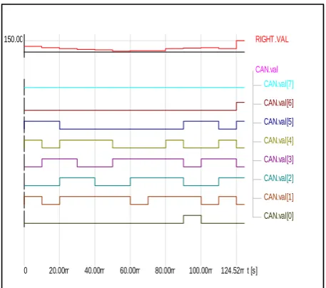
Figure 5 display the correct output numeral numbers (8 bit) of the microcontroller 18F4550.
The measured distance in cm by the four GP2D12 sensors is converted in serial digital information. FPGA treats this binary information to give action to actuators.
RIGHT.VAL 150.00
CAN.val CAN.val[7]
CAN.val[6]
CAN.val[5]
CAN.val[4]
CAN.val[3]
CAN.val[2]
CAN.val[1]
CAN.val[0]
[image:3.595.55.282.355.517.2]t [s] 0 20.00m 40.00m 60.00m 80.00m 100.00m 124.52m
Figure 5. Digital output of the microcontroller
[image:3.595.315.544.405.607.2]QuickDigGraph1
DROITE.VAL 150
-50
GAUCHE.VAL 150
-50
AVANT.VAL 150
-50
robot_1.m_avant
robot_1.m_arriere
Sheet2.S_TG
Sheet2.S_TD
[image:4.595.55.293.83.287.2]t [s] 0 25m 50m 75m 100m 125m 150m 175m 200m 240m
Figure 6. Simulation for output of the system
Figures 7 show the simulation results using VHDL-AMS of this remote control algorithm when the robot performs an autonomous navigation with a veering angle on the left or on the right. Figures 8 show the simulation results using VHDL-AMS of this remote control algorithm when the robot goes forward or back forward. These two active operations can be realized at the same time when the robot navigates actually in any configurations of environments.
QuickDigGraph1
FRONT_Dist....
150.00
robot_1.clkout
robot_1.tourne[...
robot_1.tourne[...
robot_1.tourne[...
robot_1.tourne[...
t [s]
0 20.00m 40.00m 60.00m 80.00m
Figure 7. Control Stepper Motor
NAVIGATION
FRONT_Dist.VAL 150.00
robot_tous.clkout
robot_tous.marche[4]
robot_tous.marche[3]
robot_tous.marche[2]
robot_tous.marche[1]
robot_tous.marche[0]
t [s]
[image:4.595.312.541.84.327.2]0 20.00m 40.00m 60.00m 80.00m 110.04m
Figure 8. Control DC motors
6.2
Experimental results
To explain experimental tests realized in laboratory, the L298 Motor Driver with optocoupler card used (First on-board 5 LEDs, for controlling the entertainment of the robot by the two DC motors) and the ULN2803 with optocoupler card (4 LEDs, last ones used to clarify the steering angle realized by the stepper motor installed in the front axle). Table1 shows the rotation movement of the two DC motors which are controlled by the 5 port pins as follows (Drive 0, Drive 1, Drive 2, Drive 3 and ENA_ENB).
Table 1. Control of the rotation movement of DC motors
Drive0/Drive2 Drive1/Drive3 ENA_B DC Motor 1/DC Motor 2
* * 0 off
0 0 1 Brake
0 1 1 Forward
1 0 1 Reverse
1 1 1 Brake
(Led1, Led2, Led3, Led4 & Led5) are used to indicate the reaction of the two DC motors.
(Led6, Led7, Led8 & Led9) are used to indicate the reaction of the stepper motor.
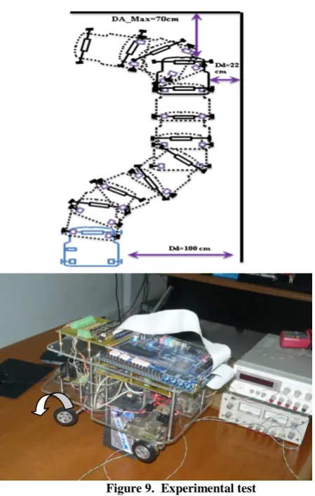
In this paragraph, present an example of experimental test: As shown in Figure 9, the direction of the mobile robot is forward. Beginning at the start point, the robot intelligibly veers on the right to reach the distance (22cm) for monitoring wall application. When avoiding an obstacle in its front, it veers 90° on the left. All operation is realized with exact information compared to simulation results.
Right Distance
Left Distance
Front Distance
Output 3:Feed Forward
Output 4:Back Forward
Output 1:Veering on the Left
Output 2:Veering on the Right
Ph3
Ph2
Ph1
Ph0
Front distance
4
p
h
ase
s o
f
th
e
S
tep
p
er
M
o
to
r
ENA/ENB
Drive [3]
Drive [2]
Drive [1]
Drive [0]
2
DC M
o
to
Figure 9. Experimental test
Figures 10 and 11 shows respectively the action on the two DC motors and the stepper motor. This result can be interpreted and compared by simulation results shown by the configuration of LEDs for DC motors and the stepper motor in table 2
NAVIGATION
FRONT_Dist.VAL 150.00
RIGHT_Dist.VAL 150.00
LEFT_Dist.VAL
150.00
robot_tous.clkout
robot_tous.marche[4]
robot_tous.marche[3]
robot_tous.marche[2]
robot_tous.marche[1]
robot_tous.marche[0]
t [s] 39.65m 50.00m 60.00m 70.00m 80.00m 89.84m
Figure 10. Simulation for DC motors
QuickDigGraph3
FRONT_Dist.VAL 150.00
RIGHT_Dist.VAL
150.00
LEFT_Dist.VAL 150.00
robot_tous.phase[3]
robot_tous.phase[1]
robot_tous.phase[2]
robot_tous.phase[0]
t [s]
[image:5.595.316.543.84.303.2]0 20.00m 40.00m 60.00m 89.67m
Figure 11. Simulation for stepper motor
Table 2. Indication Leds for DC motors and Stepper motor
DC motors Led 1
(ENA/ENB)
Led 2 (Drive 3)
Led 3 (Drive 2)
Led 4 (Drive 1)
Led 5 (Drive 0)
ON ON OFF ON OFF
Stepper Motor Led 6
(Ph3)
Led 7 (Ph2)
Led 8 (Ph1)
Led 9 (Ph0)
ON OFF OFF OFF
OFF ON OFF OFF
OFF OFF ON OFF
OFF OFF OFF ON
7.
CONCLUSION
In this research, the following features of the proposed an intelligent algorithm control have been verified and proven with SIMPLORER simulation and real time implementation A mixed-signal design and simulation environment that satisfies all of the considerations listed above is VHDL-AMS (the VHDL language with analog and mixed-signal extensions) which allows us to simulate our platform before implementing the algorithm on FPGA.
Experimental results are compared to simulation ones done with VHDL-AMS and prove effectively that the different reaction of actuators is similar and in accordance with those obtained with the Simplorer environment.
8.
REFERENCES
[1] A. New, W. Aung, and Y. Myint, “Software implementation of obstacle detection and avoidance system for wheeled mobile robot,” In Proc. World Academy of Science, Engineering, and Technology, Vol. 18, pp. 563–568, Jui. 2008.
[2] J. Shen and H. Hu, “A Matlab-based Simulator for Autonomous Mobile Robots”; 3rd Innovative Production Machines and Systems Virtual International Conference, pp. 2–13, Jul. 2007.
[3] I. Alsonosi, “Low Cost Obstacle Detection System for Wheeled Mobile Robot”; UKACC International Conference on Control 2012, Cardiff, UK, pp. 3–5, Sep. 2012
DA_Max=70
cm
Dd=22 cm
100 cm
„1‟
„0‟ „1‟
„1‟
„0‟
ENA/ENB
Drive [3]
Drive [2]
Drive [1]
Drive [0]
„1‟
„0‟ „1‟
„1‟
„0‟
DA_Max=70
cm
Dd=22 cm
100 cm
Ph3
Ph2
Ph1
[4] I. Levin, E. Kolberg and Y. Reich, “Robot Control Teaching with a State Machine-based Design Method”; International Journal of Engineering Education, Vol. 20, no. 2, pp. 1–10, 2004.
[5] A. Z. Mansoor, M. R. Khalil and O. A. Jasim, “Position Control of DC Servo Motrs using Soft-core Processor on FPGA to Move Robot ARM”; Journal of Theoretical and Applied Information Technology, Vol. 32, no. 1, pp. 99– 106, Oct. 2011.
[6] C. Abdelmoula, F. Chaari and M. Masmoudi,“A new design of a robot prototype for intelligent navigation and parallel parking”, Journal of Automation, Mobile Robotics and Intelligent Systems, Vol. 3, no. 2, pp. 47– 58, Mar. 2009.
[7] C. Abdelmoula, H. Rouabeh and M. Masmoudi, “Behavior Control of a New Designed Mobile Robot Based on Fuzzy Logic and Neuro Fuzzy Approaches for MonitoringWall”; International Journal of Intelligent Engineering and Systems, Vol. 6, no. 3, pp. 17–26, Sep. 2013.
[8] S. I. Amer , M. N. Eskander and A. M. Zaki, “Positioning And Motion Control For Mobile Robot”; International Journal of Emerging Technology and Advanced Engineering, Vol. 2, no. 11, pp. 498–504, Nov. 2012.
[9] T. E. McDermott, R. Juchem and D. Devarajan, “Distribution Feeder and Induction Moto Modeling with VHDL-AMS”, 2006 IEEE/PES T&D Conference and Exposition Proceedings, 21–26 May 2006, Dallas.
[10] A. Fakhfakh, S. Feki, Y. Hevé, A. Walha and N. Masmoudi, “Virtual prototyping in power electronics using VHDL-AMS application to the direct torque control optimisation”, Journal of Applied Sciences, vol. 6, no. 3, pp.572–579, Jan. 2006.