Optimal Scheduling of Flowshop Batch Process for
Zero-Wait and No Intermediate Storage Transfer Policy
H. Abdel Samad
Teaching Assistant Chemical Engineering Department- High
Institute of Engineering Shorouk City
H. Moselhy
Associated Professor Chemical Engineering Department- High
Institute of Engineering Shorouk City
S. Aly
Professor Chemical and Petroleum Refining
Engineering Department Suez University
M. E. Awad
Associated Professor Chemical and Petroleum Refining
Engineering Department Suez University
ABSTRACT
The scheduling zero-wait (ZW) and no intermediate storage transfer (NIS) policy of multi-product batch processes in order to produce a number of low volume high value-added chemical products because of its economic impact.
It involves various parameters such as makespan (completion time) which is recognized as one of the important design parameter as it helps to decide for the best scheduling design and normally used as the main parameter for selecting the optimal production sequence which involves various parameters such as batch process recipes, sequence of production and transfer policy for product intermediates. In this paper, we present a development, solution and computational performance evaluation of optimal scheduling for multiproduct batch process with two commonly used transfer policies namely zero wait (ZW) and no intermediate storage (NIS) by using computer program language software (Java) which simplify and improve the determination of Makespan and select the optimum sequence due to the minimum Makespan.
Keywords
Scheduling, Batch processes, Makespan, Production Sequence, Zero Wait, No Intermediate Storage.
1.
INTRODUCTION
Batch processes play an important role in producing low volume and high value-added chemical and biochemical products. In batch process operations; production scheduling is to determine the most efficient way to produce a set of desired products in a given amount of time while utilizing a set of limited resources, some processing equipment, and processing recipes. The tasks to be scheduled usually take place in multiproduct batch plants, in which a wide variety of different products can be manufactured via the same recipe or different recipes by sharing limited resources, such as equipment, material, time, and utilities.
The different types of interstage storage policies which have frequently been studied are unlimited intermediate storage (UIS), finite intermediate storage (FIS), no intermediate storage (NIS), zero wait (ZW), mixed intermediate storages (MIS) policies and process intermediate storages(PIS). Sometimes, the intermediate product produced in a batch process is not stable and cannot wait and must be transferred immediately to the next stage. The zero-wait formulation with completion times for scheduling problem in batch processes is first presented by Ku and Karimi [11], but this model did not
include the setup times. Considering setup times have significant influent on batch operations, complex scheduling descriptions with transfer and setup times under ZW Policy are also studied by Jung, Lee, Yang, and Lee[8], Kim, Jung, and Lee [10], Lee et al. [15], Shafeeq et al. [20] where they proposed a matrix-based completion algorithm for ZWSP in multiproduct batch processes. Recently, M-G Dong et al. [16] proposed a novel hybrid permutation based differential evolution for zero-wait scheduling problems of batch plant with high quality solution in short computational time. Most of the currently available methods for determining makespan are based on complex mathematical programming techniques mostly use of mathematical methods such as mixed integer linear programming (MILP) and mixed integer nonlinear programming (MINLP) in all the formulations for determining minimum makespan for batch processes (Jung et al., [8]; Kim et al.,[10]; Moon et al., [17]; Biegler et al., [1]; Das et al., [4]; Caraffa et al., [21]; Burkard et al., [3]; Dupont and Dhaenens-Flipo, [14]; Lee et al., [15]; Ryu and Pistikopoulos Efstratios, [19]. Although it is capable of providing the optimal solution, but it doesn’t provide other near optimal solutions from which a designer should have a flexibility to choose, especially when there are subjective constraints that need to be considered. Also, they require good understanding on formulating the batch scheduling problem.
In this paper the scheduling zero-wait (ZW) and no intermediate storage (NIS) transfer policy of multi-product batch processes involves various parameters of which makespan is normally used as the main parameter for selecting the optimal production sequence, at firstly uses of traditional Gantt chart method which is simple and could also generate design options that are near optimal based on makespan calculation and focuses on using computer programming language (Java) which simplify and improve the determination of Makespan for each sequence and select the optimal sequence due to the minimum Makespan.
2.
OPTIMUM BATCH PRODUCTION
SEQUENCE
The optimum production sequences for batch processes
3.
GANTT CHART
Commonly, It is used in project management and it is one ofthe most popular and useful ways of showing activities (tasks or events) displayed against time. It is most commonly used for tracking project schedules. For this it is useful to be able to show additional information about the various tasks or phases of the project. Typically, tasks are shown on the vertical axis, and the project time span is represented on the horizontal axis. Each task has a corresponding bar that shows the time span required for that task. The bar can be filled in to show the percentage of the task that has been completed. Gantt charts also indicate dependences, those tasks that are dependent upon other tasks.
4.
MATHEMATICAL MODEL
DESCRIPTION
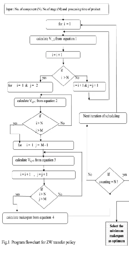
A general mathematical model to calculate the total completion time (makespan) of batch process with number of products " N " and number of stages " M " based on matrix formulation and (Fig.1) and (Fig.2) describes the flowchart of programming language (Java) used for description the calculation and estimation of optimal sequence for any number of products must be schedule and by giving the values of makespan of each sequence with its idle times and holding time in case of (NIS) transfer policy and also select the optimum sequence for batch process.
For example if we schedule four product A, B , C and D in three stages S1, S2 and S3. So, according to the matrix approach
as shown in table 1 and table 2 where at first arrangement the products and stages of batch process as the form of matrix { rows & column } at which rows refers to products and column refers to units or stages {Amir Shafeeq, et al .[20]}.
4.1 Zero Wait (ZW) Transfer Policy
1 -2..M = J V (3) 1 -1...N = i 1 + j i, T + ) j 1, + i T -1 + j i, (V = j i, V 1 -2...M = J (2) 1 -1...N = i 1 + j i, T -) j 1, + i T + j i, (V = 1 + j i, V (1) 1 -1...N = i i,2 T -1,1 + i T = i,2
m
1
1
1
1
,
,
j
i,
T
makespan
j
n
i
n
i
V
i
m
m
i
T
(4)4.2 No Intermediate Storage (NIS) Transfer
Policy:
1 -1....M = J (8) 1 -2....N = i ) 1 + j 1, -i H + 1 + j i, (T -) j 1, + i T + j i, (V = 1 j , i V 1 -1...M = J (7) 1 -1...N = i j i, V -= 1 -j i, H (6) 1 -2....M = J 1 + j 1, T -) j 2, T + j 1, (V 1 j i, V (5) 1 -1....N = i 0 = m i, H & 0 = ,1 i V 5.
PROBLEM STATEMENT
The production task to produce one batch of each product where the completion time calculation is performed for zero wait transfer policy (ZW) as we presented in example1 and example 2 where the intermediate products is not stable and must be transferred to next stage. Also, the completion time calculation (Makespan) evaluation is performed for flowshop (multiproduct) batch process using No Intermediate Storage (NIS) policy as we presented in example 3 where the intermediate is allowed to wait in the same unit from which it is produced until the next unit is available. The time of waiting in the unit known as holding time for which the succeeding product has to stay in the same unit till the next unit has finished processing the preceding product.
In the two types of transfer policy firstly, Gantt chart method is used to determine the production sequence on various stages of feasible sequence for batch process for the two types. Later, computer programming Java language applied to generate all possible sequence with the value of makespan for each sequence and determine minimum makespan as the optimal sequence.
6.
EXAMPLES
The proposed method (Java programming language) will be examined using three case studies reported in literature for comparison.
6.1. Example 1
Four products namely P1, P2, P3 and P4 based on four unit
operation S1, S2, S3, and S4 are produced in a batch process and
shown in table 3 {Ming et al, [16]}.
Gantt chart observed several possible paths (Fig.3) that can estimate of makespan and also observed that there is some discontinuity path which refer to the idle time between stages (Table 4) which must estimate this value of idle time before determining of makespan due to the fact of accordance with zero-wait transfer policy so, in determination of makespan it is important to estimate the value of idle time between stages. It is clear that, from observation of Gantt chart (Fig.3) there are some of possible paths that indicate the makespan of batch process which is illustrated in example 1.
One of these paths by taking the sum of P1S1, P1S2, P1S3, P1S4,
P2S4, P3S4 and P4S4, and also must include the idle time
between P1S4and P2S4 these idle time are due to the last stage
of first product (P1) finishes before the second product (P2) in
last stage begins. Also, idle time between P2S4, P3S4 which
similarly, the second product (P2) in the last stage finishes
before the last stage of third product (p3) begins and the idle
time between P3S4, P4S4 also, means the third product (P3) in
last stag finishes before the last stage of the fourth product (P4)
begins.
Makespan = [14+45+49+37+46+30+20] + [2+17+0] = 260 hr.
The other possible path to calculate the makespan is the sum of P1S1, P2S1, P3S1, P3S2, P3S2, P3S4 and P4S4 and also must
include the idle time between P1S1 and P2S1 between P3S4 and
P4S4.
Makespan = [14+36+29+45+30+19+20] + [46+0+21] = 260 hr.
It is clear from calculation of Makespan for any possible path of production sequences is to be the same value. i.e. in production sequence [P1-P2-P3-P4,] the Makespan calculations
The summary of results of the proposed method is shown in table 5, which confirmed with results obtained and which ensures our strategyand (Fig.4) represented the Gantt chart for optimal sequence (P2- P1- P3- P4 ). Also, table 6 stated the value
of idle time between stages for optimal sequence.
6.2 Example 2
Batch process producing six products in the sequence of product A followed by product B then product C, then product D, then product E, and finally F using four stages operation namely , S1, S2, S3,and S4 which shown in table 8
{D.B.Birewar et al, [ 2]}.
From observation of Gantt chart (Fig. 5) there are some of possible paths that indicates the makespan of batch process illustrate in example 2. From observation to chart it is clear that, it must estimate the value of idle time between stages which presented in table 9 before determining of makespan due to zero-wait transfer policy (ZW).
One of these paths by taking the sum of AS1, AS2, AS3, AS4,
BS4, CS4, DS4, ES4 and FS4, and which must include the idle
time between BS4 and CS4, CS4 and DS4, ES4 and FS4.
Makespan = 10+20+5+30+10+5+10+15+10+6+14+6=141 hr Also, from observations of Gantt chart for all possible paths (sequence) the value of makespan would be the same value which equal 141 hr for any sequence selected. As we presented in section 2 {optimum sequence} to estimate the possible number of production sequences at which can be calculated as possible production sequences p (n) = n! So for the current case study which scheduling six product, the possible production sequence P(6) = 6! = 720 production sequence, the computational result will be difficult to been shown in this section so, in table 10 we will present the summary of runs of computational results for current example.
6.3. Example 3
Four products in the sequence of product A followed by product B then product C, and finally D using Six stages operation namely , S2, S3, S4, S5and S6 which shown in table 14
{J.H.Jung et al,[8]}.
It is observed from Gantt chart (Fig.8) there another variable {Shaded area} which known as holding time which is in addition to the idle time between units according to the fact of accordance proposed policy which must estimate this value of idle and holding time between stages before determining of makespan.
Also, from Gantt chart observation there are some of possible paths that indicate the makespan of batch process illustrate in the current example. one of these paths by taking the sum of AS1, AS2, AS3, AS4, AS5, AS6, BS6, CS6 and DS6, and also
must include the idle time between AS6 and BS6, BS6 and P3S6,
P3S6 and P4S6
Makespan = 10+15+20+12+8+11+13+9+4 + [0+0+8] = 110 hr.
The second possible path to calculate the makespan by taking the sum of AS1, BS1, BS2, BS3, BS4, BS5, BS6, CS6 and DS6,
and also must include the idle time between AS1 and BS1, BS6
and CS6, CS6 and DS6 and also must include the holding time
of product "B" in S2.
Makespan= 10+15+8+12+10+9+13+9+4+ [0+0+8]+ 12=110 hr.
Also, from observations of Gantt chart for all another possible paths the value of makespan would be the same value which is equal =110hr.
Table 1. Products and stages arrangement of ZW transfer policy
Products / Stages S1 S2 S3
A TAS1 TAS2 TAS3
V1,1 V1,2 V1,3
B TBS1 TBS2 TBS3
V2,1 V2,2 V2,3
C TCS1 TCS2 TCS3
V3,1 V3,2 V3,3
D TDS1 TDS2 TDS3
where TiSn: processing time of product in stage
Vn,m: idle time of products between stage
Table 2. Products and stages arrangement of NIS transfer policy
Products /Stages S1 S2 S3
A TAS1 TAS2 TAS3
V1,2 V1,3
B TBS1 H1,1 TBS2 H1,2 TBS3
V2,2 V2,3
C TcS1 H2,1 TcS2 H2,2 TcS3
V3,2 V3,3
D TDS1 H3,1 TDS2 H3,2 TDS3
Where Hn,m : The holding time of product in stages
Table 3. The process data of Example 1
Products Unit ( Processing time ), hr
S1 S2 S3 S4
P1 14 45 49 37
P2 36 12 39 46
P3 29 35 50 30
[image:3.595.308.541.451.511.2]P4 45 30 19 20
Table 4. The idle time between stages of Example 1
Product Unit ( Processing time ), hr
S1 S2 S3 S4
P1 and P2 46 37 0 2
P2 and P3 0 17 13 17
[image:3.595.305.539.542.756.2]P3 and P4 21 31 11 0
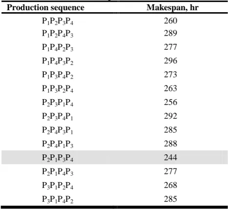
Table 5. Computational results for all production sequences:
Production sequence Makespan, hr
P1P2P3P4 260
P1P2P4P3 289
P1P4P2P3 277
P1P4P3P2 296
P1P3P4P2 273
P1P3P2P4 263
P2P3P1P4 256
P2P3P4P1 292
P2P4P3P1 285
P2P4P1P3 288
P2P1P3P4 244
P2P1P4P3 277
P3P1P2P4 268
Production sequence Makespan, hr
P3P4P1P2 304
P3P4P2P1 277
P3P2P1P4 267
P3P2P4P1 311
P4P2P1P3 270
P4P2P3P1 282
P4P3P1P2 294
P4P3P2P1 293
P4P1P2P3 301
P4P1P3P2 304
The summary of results of the proposed method is shown in table 5 for scheduling four products which indicates P2P1P3P4
was the optimal production sequence according to minimum value of makespan with value 244 hr.
Table 6. The idle time between stages for optimal sequence (P2-P1-P3-P4) of Example 1
Product Unit ( Processing time ), hr
S1 S2 S3 S4
P1 and P2 0 2 8 11
P2 and P3 30 14 0 13
P3 and P4 21 31 11 0
Table 7. Comparison of results for Example 1
Ming et al [ 16 ] Present work
Method
HPDE ( Hybrid
permutation differential
evolution)
Matrix approach using Java Computer
programming language
Feasible sequence P1P2P3P4 P1P2P3P4
Makespan ( hr) 260 hr 260 hr
Optimal sequence P2P1P3P4 P2P1P3P4
Makespan (hr) 244hr 244 hr
The summary of results of the proposed method is shown in table 7 along with those of Ming et al [16] where the total completion time (makespan ) using HPDE of feasible production sequence (P1P2P3P4) with value 260 hr and the
optimal production sequence (P2P1P3P4) with value 244 hr
which confirmed with results obtained and ensures our strategy.
Table 8. The process data of Example 2
Products Unit ( Processing time ), hr
S1 S2 S3 S4
A 10 20 5 30
B 15 8 12 10
C 20 7 9 5
D 14 6 15 10
E 6 11 5 15
F 13 7 17 10
Table 9. The idle time between stages of Example 2
Product Unit ( Processing time ), hr
S1 S2 S3 S4
A and B 0 4 7 4
B and C 0 6 0 5
C and D 0 4 9 4
Product Unit ( Processing time ), hr
S1 S2 S3 S4
D and E 18 11 13 0
E and F 0 13 3 2
Table 10. Summary of computational results of production sequences
Feasible sequence
Makespan (hr)
Optimal sequence
Makespan (hr)
A-B-C-D-E-F 141 hr E-D-B-A-F-C
E-B-D-A-F-C 117 hr
The summary of computational results of the proposed method is shown in table 10 which indicates two optimal production sequence according to minimum value of makespan with value 117 hr. for production sequence ( E-D-B-A-F-C) and the proposed method indicates another optimal production sequence (E-D-B-A-F-C) according to makespan value117 hr. due to the total processing time of products B & D was the same in all stages and in table 11and 12 represented the idle times between stages for two optimal production sequences. Also, (Fig.6) and (Fig.7) showed the Gantt chart for these sequences.
Table 11. The idle time between stages for optimal sequence no. 1
Product Unit ( Processing time ), hr
S1 S2 S3 S4
E and B 0 4 7 4
B and D 0 6 0 5
D and A 0 4 9 4
A and F 18 11 13 0
F and C 0 13 3 2
Table 12. The idle time between stages for optimal sequence no. 2
Product Unit ( Processing time ), hr
S1 S2 S3 S4
E and D 0 3 4 4
D and B 0 9 2 4
B and A 0 2 10 5
A and F 18 11 13 0
F and C 0 13 3 2
Table 13. Comparison of results for example 2.
D.B.Birewar et al, [2] Present work
Method
Mixed Integer Linear Programming
(MILP)
Matrix approach using Java Computer programming
Language
Feasible sequence A-B-C-D-E-F A-B-C-D-E-F
Makespan ( hr) --- 141 hr.
Optimal sequence E-B-D-A-F-C E-B-D-A-F-C
E-D-B-A-F-C
Makespan (hr) 117 hr. 117 hr.
hr. and the proposed method indicates another optimal production sequence (E-D-B-A-F-C) according to makespan value 117 hr. thus gives more flexibility to our proposed method than Mixed Integer Linear Programming (MILP) method which used by D.B.Birewar et al, [2] , at which confirmed with results obtained and which ensures our strategy.
Table1 14. The process data of Example 3
Products Unit ( Processing time ), hr
S1 S2 S3 S4 S5 S6
A 10 15 20 12 8 11
B 15 8 12 10 9 13
C 10 22 9 5 6 9
[image:5.595.310.538.112.568.2]D 20 12 7 10 10 4
Table 15. Computational results for all production sequences
Production sequence Makespan, hr.
ABCD 110
ABDC 108
ADBC 110
ADCB 120
ACDB 114
ACBD 110
BCAD 118
BCDA 125
BDCA 135
BDAC 123
BACD 105
BADC 111
CABD 115
CADB 123
CDAB 123
CDBA 123
CBAD 113
CBDA 130
DBAC 120
DBCA 133
DCAB 133
DCBA 130
DABC 120
DACB 123
The summary of results of the proposed method is shown in table 15 where makespan of feasible production sequence (A-B-C-D) with value 110 hr. and the optimal production sequence (B-A-C-D) with value 105 hr. which confirmed with results obtainedand ensures our strategy.
7.
CONCLUSION
The present study presents scheduling of flowshop batch process with zero-wait (ZW) and No Intermediate Storage (NIS) transfer policy using computer programming language Java software which simplified and determine total completion time (makespan) for all possible sequences and the optimal sequence due to its minimum makespan for scheduling of multi-product batch process. The proposed software when applied to problems previously reported in the literature yielded optimum sequences which are consistent with different approach used. It is evident that the performance of the software is quite encouraging, characterized by its simplicity and implementation for any numbers of products in batch processes which can be difficult by using of hand calculations.
[image:5.595.47.302.162.237.2]
Fig.3 Gantt chart of example 1 for feasible sequence (P1-P2 -P3-P4) with makespan 260 hr
Fig.4 Gantt chart of example 1 for optimal sequence (P2-P1-P3-P4) with makespan 244 hr
Fig.5 Gantt chart of example 2 for feasible sequence (A-B-C-D-E-F) with makespan 144 hr
Fig.6 Gantt chart of example 2 for optimal sequence
(E-B-D-A-F-C) with makespan 117 hr
Fig.8 Gantt chart of example 3 for feasible sequence (A-B -C-D with makespan 110 hr
Fig.9 Gantt chart of example 3 for optimal sequence
(B-A-C-D) with makespan 105 hr
Nomenclature
ZW Zero Wait
NIS Non Intermediate Storage ZWSP Zero Wait Scheduling Problem MINLP Mixed Integer Non Linear Programming MILP Mixed Integer Linear Programming HPDE Hybrid Permutation Differential Evolution
8.
REFERENCES
[1] Biegler, L.T., Grossmann, I.E. and Westberg, A.W., (1997).Systematic Methods of Chemical Process Design. (Prentice-Hall).
[2] Birewar, D.B. and Grossmann, I.E., 1989, "Efficient optimization algorithms for zero-wait scheduling of multiproduct batch plants". Ind Eng Chem Res, 28(9): 1333–1345.
[3] Burkard, R.E., Fortuna, T.C. and Hurkens, A.J., 2002, "Makespan minimization for chemical batch processes using non-uniform time grids". Comput Chem Eng, 26(9): 1321–1332.
[4] Das, H., Cummings, P.T. and Le Van, M.D., 1990, "Scheduling of serial multiproduct batch processes via simulated annealing". Comput Chem Eng, 14(12): 1351– 1362.
[5] Dupont, L. and Dhaenens-Flipo, C., 2002," Minimizing the makespan on a batch machine with non-identical job sizes: an exact procedure". Comp Oper Res, 29: 807–819. [6] Edgar, T.F., Himmelblau, D.M. and Lasdon, L.S., (2001).
Optimization of Chemical Processes (2nd edition). (McGraw Hill).
[7] Grossmann, I. and Morari, M., Morari, M. (eds). (CACHE Corporation, Austin, TX)
[8] Jung, J., Lee, H., Yang, D. and Lee, I., 1994, "Completion times and optimal scheduling for serial multi-product processes with transfer and set-up times in zero-wait policy". Comput Chem Eng, 18(6): 537–544.
[9] Jun-Hyung Ryu and Efstratios N. Pistikopoulos (2007) "A novel approach to scheduling of zero wait batch processes under processing time variations". Computers and Chemical Engineering, 31: 101–106.
[10]Kim, M., Jung, J.H. and Lee, I.B., 1996, "Optimal scheduling of multiproduct batch processes for various intermediate storage policies". Ind Eng Chem Res, 35(11): 4058–4066.
[11]Ku, H.M. and Karimi, I.A., 1988," Scheduling in serial multiproduct batch processes with finite interstage storage: a mixed integer linear program formulation". Ind Eng Chem Res, 27(10):1840–1848.
[12]Ku, H.M. and Karimi, I.A., 1990, "Completion time algorithms for serial multiproduct batch processes with shared storage". Comput Chem Eng, 14(1): 49–69. [13]Ku, H.M. and Karimi, I.A., 1992, Multiproduct batch
plant scheduling, in CACHE Process Design Case Studies,
[14]L. Dupont and C. Dhaenens-Flipo (2002) "Minimizing the makespan on a batch machine with non-identical job sizes: an exact procedure". Computers and Operations Research, 29: 807–819.
[15]Lee, D.S., Vassiliadis Vassilios, S. and Park, J.M., 2002, "List-based threshold-accepting algorithm for zero-wait scheduling of multiproduct batch plants". Ind Eng Chem Res, 41(25): 6579–6588.
[16]Ming-Gang Dong and Ning Wang (2012), "A novel hybrid differential evolution approach to scheduling of large scale zero wait batch process with setup times". Comput Chem Eng, 45:72-83.