27
Improving Performance of Wireless Mesh Networks
Ghule S. J.
M.B.E.Society’s College of Engineering.Ambajogai, Maharashtra.
B. M. Patil
M.B.E.Society’s College of Engineering, Ambajogai, Maharashtra.
ABSTRACT
Inspite of many advancements in multihop multiradio Wireless Mesh Network, it experiences frequent link failures because of increasing bandwidth demand, channel interference, etc. The Autonomous Reconfiguration System (ARS) presented in this paper helps Wireless Mesh Network to overcome such failures, thereby improving the performance of Wireless Mesh Network. ARS passively monitors the network and checks link quality, in case of failures it generates reconfiguration plan and forwards it to neighboring nodes.
General Terms
Wireless Mesh Network, Routing.
Keywords
Autonomous Reconfigurable System, multiradio Wireless Mesh Network, Wireless Link Failure.
1.
INTRODUCTION
[image:1.595.306.526.422.542.2]Wireless Mesh Networks can be defined as the wireless Networks in which each node is connected to other node through one or more hops. WMNs are widely used nowadays. Inspite of improving technologies WMNs still experiences frequent link failures because of increasing bandwidth demands, channel interference, etc. Frequent link failures may result in loss of data. This may harm the use of Wireless Mesh Network. Therefore Wireless Mesh Network has to overcome these link failures.
Fig.1: Wireless Mesh Network
WMNs have several advantages; some of them are as follows-
i. WMNs are self forming. Once the mesh nodes have been configured WMNs are automatically formed.
ii. WMNs are fault tolerant
iii. WMNs can be easily deployed with low cost.
Wireless medium has a half duplex nature. IEEE 802.11 radios are typically single channel radios. Use of such radios can severely degrade the capacity of network. Therefore multiradio i.e. multi channel radios are used in WMNs [17].
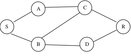
Wireless Mesh Network has the property of self healing from frequent link failures, but still this approaches has some drawbacks such as: 1) Resource allocation algorithm – The resource allocation algorithm uses centralized policy which provides optimal solutions but it global reconfiguration changes. In case of frequent link failures, global reconfiguration changes are infeasible due to communication overhead [3]. 2) Greedy channel assignment algorithm only considers the settings of faulty link(s) thereby reducing the requirement of changes in network. The Greedy channel assignment works by estimating the load on each virtual link. It then visits each virtual link with decreasing order of load. On encountering with particular node it greedily assigns a channel with minimum interference. This may not provide full improvements which may be attained by determining the configuration of the neighboring mesh routers while recovering faulty links [4]. 3) Fault tolerant routing protocols [5], [6] uses detour path. For example consider fig. 2. shown below.
Fig. 2. Topology for illustration
Suppose A is source and H is destination node. Routes to H from A are via B, C, D with cost 7, 6, and 5 respectively. With fault tolerant routing route from D will be selected as it seems to be shortest. Only G and H are aware of updated state of link G-H. As A is unaware of failure of link G-H it will forward packet through D. when packet arrives at G it is then rerouted via F. In case of large networks this greedy approach may lead to dead end. Also it requires a detour path to be available which may need extra network resources.
Autonomous Network Reconfiguration System (ARS) overcomes the above limitation by allowing a multiradio WMN to self reconfigure its network settings for real time recovery of network from link failures. ARS consist of reconfiguration planning algorithm which identifies the configuration changes in local network for recovery by minimizing changes in settings of healthy network. In short, ARS initially searches for feasible configuration changes that are possible around a faulty area.
A
B
C
D
E
F
G
H
I
A
B
G D
F C
E
H
3
3
1
2
3 2
2
4 1
3
2
[image:1.595.39.246.520.622.2]28 Then by using current network settings as constraints, it
generates reconfiguration plan which will need minimum changes in settings of healthy network.
Need of Self Reconfigurability
In case of dynamic link failures to maintain performance of WMNs remains a challenging problem [7]. Consider Wi-Fi enabled campus. In such campus there can be other wireless devices such as Bluetooth, Infrared, etc. Use of such devices may result into interference in WMN, resulting into severe degradation in link quality. To overcome from such link failures local links can switch from tuned channel of link to other non interfering channels [8], [9].
Now consider a video- conferencing room, where QoS demands are high. Links in such room may fail to hold all attendees’ calls. To avoid communication failures links should reconnect through underutilized channels available nearby [10].
Because of spectrum etiquette or regulations [11], [12], [13] links in some area are unable to access wireless channels for specific time period. Such links can determine and use the substitute channels available in same area.
Rest of this paper is organized as follows. Section 2 describes assumptions in network. Section 3 describes architecture and algorithm of ARS. Section 4 shows results of ARS. Section 5 concludes the paper.
2.
ASSUMPTIONS
A network is assumed to consist of wireless links, mesh nodes connected in mesh, and a control gateway. Every node is equipped with n number of radios. It is assumed that multiple channels are available. Each node in mesh network periodically sends its link usage to the control gateway. Based on this information the remaining traffic is routed. The routing protocol WCETT [15] is used to check the path for flows. For route discovery AODV algorithm is used [16]. The control gateway is connected to the internet via wired connections. Control gateway generates the reconfiguration plan and forwards it to the leader nodes.
3.
ARCHITECTURE AND ALGORITHM
3.1
ARS Architecture
The fig.3. above shows the architecture of ARS. ARS is mainly subdivided into two parts network layer and device driver layer [14]. Further the network layer consists of the failure detector, group organizer, routing table manager and planner in gateway modules. The working of each module is as follows: 1) Network Planner - it works in gateway node and its function is to generate reconfiguration plan. 2) Group organizer – it is responsible for formation of groups in local mesh network. 3) Failure detector – this module keeps on continuously interacting with network monitor in the device driver layer and keeps updated routing information.4) Routing table manager – helps ARS in updating the systems routing tables. For routing in ARS AODV algorithm is used to increase the routing performance of the system
[image:2.595.298.543.69.283.2]The device driver layer consists of network monitor and NIC manager. The network monitor effectively monitors the quality of link and it is scalable to support as much multiple radios as possible. The NIC Manager changes the NIC settings based on reconfiguration plan.
Fig.3: ARS Architecture [1]
ARS runs in every node and support self reconfiguration from link failures. ARS passively monitors the network for link failures. In case of link failures ARS sends group formation message to the nodes in neighborhood. Then a leader node is elected and this leader node if it is not a control gateway forwards plan generation message to the control gateway. The plan is generated by control gateway. If there are any changes then these changes are relayed to other nodes. ARS reconfigures the network within the vicinity of link failures, other nodes remain unaffected. ARS helps in monitoring QoS attribute by equally distributing load over the nodes.
3.2
Algorithm
1] Monitoring Stage (𝑇𝑚) for each link l do
determine link- quality(q) by passive
monitoring; end for
forward the monitoring results to gateway G; 2] Detecting failure and formation of group stage (Tg)
if link j is violating requirements r of link then request group formation of link j on channel c;
end if
if request is received then participate in leader election;
3] Planning stage (M, Tp)
if node k is elected as leader then
forward plan request message (C,M) to gateway node;
else if node k is gateway itself then
request is synchronized from reconfiguration groups 𝑀𝑛;
reconfiguration plan (p) for 𝑀𝑘is generated; forward reconfiguration plan p to leader of group
𝑀𝑘;
end if
4] Reconfiguration stage (p, 𝑇𝑟)
if plan p include changes of node k then employ changes to links at T;
end if
broadcast p to neighbors if any.
Algorithm 1. ARS Operation in each mesh node[1] Link State
Planner in Gateway Routing
Table Mgr
Failure Detector
Network Monitor
Plan Generator
QoS Filter
Benefit Filter
NIC Setting Manager Group
Organizer
Group Members Grp.
Msg. New Plan
29 The above algorithm shows the operation of ARS in every mesh
node. It operates in four phases. The initial phase is the monitoring phase I which the link quality will be measured using passive monitoring. The quality values of every link will be entered in the WCETT matrix which is further used by MR – LQSR algorithm [15]. The second phase is the failure detection phase which will detect the failure in the link based on the values from the monitoring phase. In case of failure a group formation request will be generated and forwarded to neighboring nodes. After receiving the group formation request the node will participate in election. Once the leader is elected it will generate reconfiguration plan request and at gateway node the reconfiguration plan will be generated.
For routing Ad Hoc On demand Distance Vector algorithm is used. DSDV algorithm has drawbacks such as it requires continuous updating of routing table which may result in message overhead. Whereas, AODV is on demand routing, that means it updates routing table only when necessary. AODV has several advantages over DSDV, such as it is on demand distance vector, it informs link failures only to affected nodes, also reduces message overhead[16].
WCETT matrix is generated based on the path flow information received from each node. WCETT can be generated using following calculations:
WCETT matrix can be generated using following formula:
𝑊𝐶𝐸𝑇𝑇 = 𝐸𝑇𝑇𝑖
𝑛
𝑖=1
Where 𝐸𝑇𝑇𝑖 is Expected Transmission Time on link I from node x to node y.
𝐸𝑇𝑇 = 𝐸𝑇𝑋 ∗ 𝑆 𝐵
ETX is expected number of transmission, S is size of packet and B is the bandwidth of link.
4.
RESULTS OF ARS
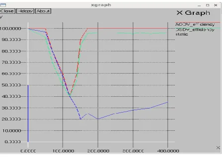
[image:3.595.309.534.70.229.2]Fig.4.and fig.5 shows the simulation results for throughput gain and channel efficiency gain. In simulation total 9 nodes were considered. Adjacent nodes are separated by 2m, and each node is equipped with different number of radios. Each flow runs at the rate of 500 kbps and the packet size is 1000 bytes.
Fig.4: Throughput gain- ARS compared with DSDV and Static Routing.
Fig.5: Channel Efficiency gain - ARS compared with DSDV and Static Routing.
Link state routing protocol, AODV and MR-LQSR protocols are used for routing and checking the quality of link. To create failure channel fault is inserted at specific time. The total experiment is run for 500 seconds.
The results observed are shown in figure 4 and 5 above. The throughput of ARS is increased as compared to DSDV and static throughput. ARS detects local link failure accurately and reconfigures the local network, whereas there is a severe degradation of throughput in static. The channel efficiency is the ratio of number of packets successfully delivered to the total number of transmitted frames. The ARS channel efficiency gain is increased over the DSDV and static routing schemes. After reconfiguration ARS was able to admit additional flow thereby improving the quality of service requirements of planning.
With 5 nodes connected physically to form WMN. Where S is Sender node, R is Receiver node, A, B, D are intermediate nodes.
[image:3.595.48.274.558.720.2]The message size was varied also the distances between the nodes were varied; with above constraints following analysis was made:
Fig. 6. Network with 5 nodes for physical illustration
S
A
B D
[image:3.595.308.524.591.684.2]30
Table. I. Analysis of 5 nodes connected in WMN
Sr N o.
Data size
Dist(m) Initial path Experimental setting Path formed Data receiv ed
1. 4 byte S-A=2m
A-R=3m S-B=4m B-D=3m D-R=3m S-A-R S-B-D-R
A, B and D are active.
A, B and D are in range.
Node A is nearer to S and R as compared to B and D
S-A-R YES
2. 7 byte S-A=2m
A-R=3m S-B=4m B-D=3m D-R=3m S-A-R S-B-D-R
A, B and D are active.
A, B and D are in range.
Node A is nearer to S and R as compared to B and D.
Node A fails
S-B-D-R
YES
3. 3 byte S-A=5m
A-R=5m S-B=1m B-D=2m D-R=1m S-A-R S-B-D-R
A, B and D are active.
A, B and D are in range.
Node A goes away from S and R as compared to B and D
S-B-D-R
YES
4. 2 byte S-A=2m
A-R=3m S-B=4m B-D=7m D-R=6m S-A-R S-B-D-R
A, B and D are active.
A and B are in range.
Node D goes out of range
S-A-R YES
5. 5 byte S-A=2m
A-R=3m S-B=4m B-D=3m D-R=3m S-A-R S-B-D-R
A, B and D are in range.
Node A and node B fails
- No
data receive d
[image:4.595.31.562.175.752.2](packet drop)
Fig. 5. Network with 6 nodes for physical illustration
With 6 nodes connected physically to form WMN. Where S is Sender node, R is Receiver node, A, B, C, D are intermediate nodes.
Table. II. Analysis of 6 nodes connected in WMN
Sr N o.
Data size
Dist(m) Initial path Experimental setting Path formed Data receiv ed
1. 7 byte S-A=3m
A-C=4m C-R=3m S-B=1m B-D=2m D-R=2m S-A-C-R S-B-D-R
Nodes A, B, C, D and E are active and in range.
Nodes A and C are far away from S and R as compared to nodes B and D
S-B-D-R
YES
2. 7 byte S-A=3m
A-C=4m C-R=3m S-B=1m B-D=2m D-R=2m S-A-C-R S-B-D-R
Nodes A, B, C, D and E are active and in range.
Nodes A and C are far away from S and R as compared to nodes B and D.
Node B fails
S-A-C-R
YES
3. 7 byte S-A=3m
A-C=4m C-R=3m S-B=1m B-D=2m D-R=2m S-A-C-R S-B-D-R
Nodes A, B, C, D and E are active and in range.
Nodes A and C are far away from S and R as compared to nodes B and D.
Node A and B fails
- No
data receive d
(packet drop)
4. 4 byte S-A=2m
A-C=1m C-R=2m S-B=3m B-D=4m D-R=3m S-A-C-R S-B-D-R
Nodes A, B, C, D and E are active and in range.
31
5.
CONCLUSION
Autonomous network Reconfiguration System presented in this paper helps WMN to self reconfigure from the local link failures thereby increasing the performance of the network. By considering only local network configuration changes ARS effectively generates the reconfiguration plans. With increased performance ARS also helps to satisfy the QoS constraint achieving up to two times increased flow by using QoS aware planning.
6.
REFERENCES
[1] K. Kim, K. Shin, “Self-Reconfigurable Wireless Mesh Networks,” IEEE/ACM Transaction on Networking, VOL. 19, No. 2, April 2011.
[2] I. Akyildiz, X. Wang, and W. Wang, “Wireless mesh networks: A survey,” Computer Networks, no. 47, pp. 445– 487, 2005.
[3] A. Brzezinski, G. Zussman, and E. Modiano, “Enabling distributed throughput maximization in wireless mesh networks-a partitioning approach,” in Proceedings of ACM MobiCom, Los Angeles, CA, Sept. 2006
[4] A. Raniwala and T. Chiueh, “Architecture and algorithms for an IEEE 802.11-based multi-channel wireless mesh network,” in Proceedings of IEEE InfoCom, Miami, FL, Mar. 2005.
[5] S. Nelakuditi, S. Lee, Y. Yu, J. Wang, Z. Zhong, G. Lu, and Z. Zhang, “Blacklist-aided forwarding in static multihop wireless networks,” in Proc. IEEE SECON, Santa Clara, CA, Sep. 2005, pp. 252–262.
[6] S. Chen and K. Nahrstedt, “Distributed quality-of-service routing in ad hoc networks,” IEEE J. Sel. Areas Commun., vol. 17, no. 8, pp. 1488–1505, Aug. 1999.
[7] L. Qiu, P. Bahl, A. Rao, and L. Zhou, “Troubleshooting multi-hop wireless networks,” in Proc. ACM SIGMETRICS, Jun. 2005, pp. 380–381.
[8] D. Aguayo, J. Bicket, S. Biswas, G. Judd, and R. Morris, “Link-level measurements from an 802.11b mesh network,” in Proc. ACM SIGCOMM, Portland, OR, Aug. 2004, pp. 121–132.
[9] D.Kotz, C. Newport, R. S. Gray, J. Liu, Y.Yuan, and C. Elliott, “Experimental evaluation of wireless simulation assumptions,” Dept. Comput. Sci., Dartmouth College, Hanover, NH, Tech. Rep. TR2004-507, 2004.
[10] T. Henderson, D.Kotz, and I. Abyzov, “The changing usage of amature campus-wide wireless network,” in Proc. ACM MobiCom, Philadelphia, PA, Sep. 2004, pp. 187–201. [11] M. J. Marcus, “Real time spectrum markets and
interruptible spectrum: New concepts of spectrum use enabled by cognitive radio,” in Proc. IEEE DySPAN, Baltimore, MD, Nov. 2005, pp. 512–517.
[12] M. Buddhikot, P. Kolodzy, S. Miller, K. Ryan, and J. Evans, “DIMSUMnet: New directions in wireless networking using coordinated dynamic spectrum access,” in
Proc. IEEE WoWMOM, Naxos, Italy, Jun. 2005, pp. 78–85. [13] K.-H. Kim and K. G. Shin, “On accurate and asymmetry-aware measurement of link quality in wireless mesh networks,” IEEE/ACMTrans. Netw., vol. 17, no. 4, pp. 1172–1185, Aug. 2009.
[14] A. P. Subramanian, H. Gupta, S. R. Das, and J. Cao, “Minimum interference channel assignment in multiradio wireless mesh networks,” IEEE Trans. Mobile Comput., vol. 7, no. 12, pp. 1459 1473, Dec. 2008.
[15] R. Draves, J. Padhye, and B. Zill, “Routing in multi-radio,
multi-hop wireless mesh networks,” in Proc. ACM MobiCom, Philadelphia, PA, Sep. 2004, pp. 114–128. [16] S. A. Ade, P.A.Tijare, “Performance Comparison of
AODV, DSDV, OLSR and DSR Routing Protocols in Mobile Ad Hoc Networks”, International Journal of Information Technology and Knowledge Management, July-December 2010, Volume 2, No. 2.
[17] K. Ramanchandran, E. Belding-Royer, and M. Buddhikot, “Interference aware channel assignment in multi-radio wireless mesh networks,” in Proceedings of IEEE InfoCom, Barcelona, Spain, Apr. 2006.
![Fig.3: ARS Architecture [1] Group Members](https://thumb-us.123doks.com/thumbv2/123dok_us/8071214.779647/2.595.298.543.69.283/fig-ars-architecture-group-members.webp)