Neuro Fuzzy based Peak Power Point Tracking for Solar
Photo Voltaic System
Kalika S.
Research Scholar Shri Venkateshwara University,
Gajraula/U.P./India
L. Rajaji
Professor, Department of EEE P.B.College of Engineering
Chennai./India
Subhash Gupta
Shri Venkateshwara University Gajraula/U.P./India
ABSTRACT
Photovoltaic systems are so versatile that it can supply any electric power need and are used for numerous applications. Recent advancements in efficiency and cost reduction have made photovoltaic systems economically competitive with traditional power sources. This paper presents an intelligent method of peak power point tracking for photovoltaic systems based on tracking the peak power point by measuring the voltage and current of the solar array to control a buck-boost DC to DC converter. Result analysis shows that the neuro-fuzzy controller can deal with different load and weather conditions and deliver more power from the photovoltaic systems. To increase the efficiency of PV panels, it must operate around the peak power point which is influenced by cell temperature and sun irradiation. A controller therefore is needed to find the peak power point and control PV output voltage according to peak power point voltage. The aim of the paper is to design and analyze neural fuzzy controller for controlling the PV system output voltage.
Keywords
Maximum Power Point, Neuro-fuzzy , Photovoltaic, PPPT, PV module.
I.
INTRODUCTION
The use of new photovoltaic solar cells has emerged as an important solution in energy conservation and demand-side management during the last decades. Because of their initial high costs, photovoltaic solar cells have not yet been an attractive alternative for electricity users who are able to buy cheaper electrical energy from the utility grid. However, they have been used extensively for water pumping and air conditioning in remote and isolated areas where utility power is not available or is too expensive to transport. Although solar cell prices have decreased considerably during the last years due to new developments in the film technology and manufacturing process [1], PV arrays are still considered rather expensive compared with the utility fossil fuel generated electricity prices [6]. After building such an expensive renewable energy system, the user naturally wants to operate the PV array at its highest conversion efficiency by continuously utilizing the maximum available output power of the array. The electrical system powered by solar cells requires special design considerations because of the varying nature of the solar power generated resulting from unpredictable changes in weather conditions, which affect the solar radiation level as well as the cell operating temperature. To improve the efficiency of PV panels, it must operate around the peak power point [2]. Maximum power point (MPP) or
peak power point (PPP) is influenced by the cell temperature and solar irradiation. Changes in temperature of the cells or irradiation will shift the point of working PV which will result in the efficiency of PV will be reduced, so that the necessary controls to adjust the point of working PV remains in MPP continuously, that is called Maximum Power Point Tracker [1][2].
Controlling of Point of work via MPPT can be done by regulating the duty cycle converter circuit that connects the PV with the load.
Several methods of control can be used, among others Incremental Conductance, paracitic capacitance and voltage constant, but these methods require a high cost and complex arrangement [4]. Compared with P&O method, the use of artificial intelligent MPPT also produce a better performance to changing environmental conditions [8]. Neural network with Multilayer Perceptron back propagation is used as an estimator to determine the MPP and the duty cycle of buck converter. With the use of neural fuzzy as MPPT, PV system is expected to work in the area MPP although there is a change in temperature and solar irradiation. Photovoltaic systems (PV) are a device that converts solar energy into electrical energy. it consists of several solar cells, each cell is associated with each other either in series or parallel to form a series of PV that is generally referred to as "PV modules". Energy conversion efficiency of solar cells depends on the maximum operating point (MPP) of PV systems [3].
In one day, solar insolation or solar irradiation is received can vary from 0.55kWh/m (2MJ/m) at cold area until 5.55kWh/m (20MJ/m) at tropic area [8]. In the sunny weather, the energy of sunlight scattering may be only 15- 20% of the global irradiance and on cloudy weather will reach 100%.
2. PV Model
irradiation and temperature of cell junctions for highly non-linear changes.
[image:2.595.75.286.119.252.2]Figure 1: I-V curve of photovoltaic panel
Figure 2: P-V curve of photovoltaic panel
Solar cell is a device which is non linear and can be expressed as a current source model as shown in Fig 3. A photovoltaic cell is basically a p–n semiconductor junction diode which converts solar light energy into electricity. Its equivalent circuit is shown by Fig. 3. A PVP is composed of np parallel modules each one including ns photovoltaic cell serial connected Fig. 4 shows the maximum power point tracker connecting the PVP module to the dc load[10] . The maximum power point tracker consists of boost dc–dc inverter with the output filter and the control system. The maximum power point tracking drives the operating point of the PVP to the Pmax detected by the control system.
The control unit switches the power transistor ON and OFF to carry out the Pmax from the PVP. When the transistor is switched ON, the current in the boost inductor increases linearly, so the diode is in the OFF stat[11] . However, when the transistor is switched off, the energy stored in the inductor is released through the diode to the load.
Figure.3. Equivalent circuit of a photovoltaic cell.
Figure.4. System configuration.
The pulsating current produced by the switching action is smoothed by the capacitive filter and a dc voltage is provided to the load[27] .
3.
NEURAL NETWORK PEAK POWER
POINT TRACKING CONTROLLER
cell temperature .
Fuzzy controller is improved by developing artificial intelligent methods by using neural network . Neural networks have the ability to adapt so that it can handle [12] non- linearity, uncertainty and parameter variations that occur in a controlled plant. One example of non-linear feed forward networks is back propagation network and radial basis function network (RBF) [19]. These two networks have different, RBF network has only one hidden layer while back propagation network have one or more hidden layers. Hidden layer of RBF network is nonlinear while the output layer is linear. Back propagation training need time longer than the RBF. But it requires less information to obtain accurate modeling and maximum power point tracking [7].
Neural network controller is used for control of duty cycle of boost converters so that the voltage of PV modules is proportional with MPP voltage at atmospheric conditions [26]. Using back propagation learning algorithm reference voltage at the MPP obtained through the learning offline. Neural network is used to obtain the maximum power voltage of the solar panels. Network has three layers consisting of input layer, hidden layer and output layer [17].
Neural network is used to determine the MPP, while fuzzy logic is used to set duty cycle of buck converter. Buck converters obtain input from PV output voltage and produce a smaller output voltage than the input voltage [13]. Fuzzy logic controller generating a control signal based on the voltage generated by the MPPT and the PV panels. The output of fuzzy controller to adjust the duty cycle of buck converter that generates a output voltage corresponding to Vmpp[16] .
Neural networks have learning algorithms, data collected through observation of PV panels are used as training data to be used for updating neural parameters [15]. In this research, neural network algorithms are designed using Multilayer Perceptron Neural Network Error Back propagation type.
The output of the neural network is the maximum power point voltage of the reference for fuzzy logic in managing the duty cycle. According to back propagation algorithm [20] requires less information for accurate modeling and searching than the maximum power point using the method of radial basis function. Neural networks used three layers, consisting of input layer, hidden and output. Network has two layers are the input voltage from the PV panel and the current from the PV panel, a single layer in the form of output voltage at the MPP and one hidden layer [22] .
Activation function used for input and hidden layers are sigmoid logarithmic while for output neurons use linear activation functions.
(a) Error membership function.
(b) Delta error membership function.
(c) Output membership function
Figure 5: Membership functions of fuzzy
[image:3.595.327.541.68.148.2]Fuzzy controller consists of two variable inputs and one output variable. Input variables consists of the error and change of error that have 5 membership functions. The output of fuzzy logic in the form of duty cycle is connected to input of buck converter circuit. Membership functions of input and output of fuzzy controller is shown on Fig.4 Error input variables will be negative if the value of the PV output voltage is above maximum power point voltage value of the resulting neural network. Fuzzy rules are used as shown in Table 1 [25] .
Table 1: Fuzzy Rules
e Δe SN N NK NP SP
SN B BS BS BS BS
N Z B BS BS BS
Z Z B B BS BS
P K K B B BS
4.
SIMULATION RESULT
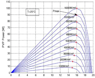
Simulation of neural fuzzy algorithm as MPPT on PV system is done by providing interference in the form of solar irradiation and temperature changes because these two variables affect PV output voltage and current. Fig 6 shows the simulation results of the PV system with a PV voltage of 18V without disturbance at irradiation of 400W/m2 and temperature of 25oC. In this simulation the neural network can recognize a change in solar irradiation to produce change in Vmpp [23].
Fig 6: P/V characteristics at constant temp T =25 C.
Using the derivative procedure of each PVP power curve, a new maximum power characteristic is extracted to indicate the optimal functioning points for the PVP (Iopt, Vopt) for different solar radiation and ambient temperature. Figs. 6 and 7 plot P = f(V) and I = f(V) curves respectively for different solar radiation G and with constant temperature T =25 C. Figs. 8 and 9 present the same parameters curves for different temperature T but with constant solar radiation G = 100 W/m2. As it is shown in Figs. 6 and 7, the current, due to the cutoff circuit is positively varying with solar radiation. However, the voltage in the open circuit remains quasi constant.
o
Furthermore, maximum power points are situated around a critical value of 16 V. The charge regulator, the MPPT, will not be perturbed enough by the solar radiation when searching the maximum power points. Figs. 9 and 10 shows that the affect of temperature is slightly significant and it needs important choice in panel and systems conception[24] .
Fig 8: I/V characteristics at constant temperature T =25oC
The temperature has a negligible effect on the cutoff circuit current. However, the open circuit voltage decays rapidly as the temperature increases.
Fig 9. I /V characteristics at constant solar radiation 1000 W/m2.
[image:4.595.42.287.224.427.2] [image:4.595.66.264.587.749.2]
5.
CONCLUSION
This paper has presented neural fuzzy for controlling PV system output voltage to operate at maximum power point although happened temperature and irradiation changes. The system was analyzed and designed and performance was studied by simulation. PV system can operate at maximum power point although occurrence of temperature and sun irradiation change can shift maximum power point. This method is fully dynamic in nature which can model dynamical complex systems that change with time following non-linear laws. These proposed algorithms command a boost dc–dc inverter to obtain the MPPT directly from the climate data solar radiation and PV cell temperature. In addition this technique gives a simplified system and low cost to implement it.
6. REFERENCES
[1] G. Y.Ayvazyan, G. H. Kirakosyan, and A. H. Vardanyan, “Maximum Power Operation Of PV System Using Fuzzy Logic Control,” Armenian Journal of Physics, Vol. 1, pp. 155-159, 2008.
[2] Chouder, F. Guijoan, and S. Silvestre, “Simulation of Fuzzy Based MPP Tracker And Performance Comparison with Perturb and Observe Method,” Revue des Energies Renouvelables, Vol. 11 No (4), 2008.
[3] M. S. Aldhobani and R. John, “Maximum Power Point Tracking Of PV System Using ANFIS Prediction And Fuzzy Logic Tracking”, in Proc. Of The International Multi Conference of Engineers andComputer Scientists 2008, Vol. II, IMECS 2008. Hong Kong, 19-21 March 2008.
[4] L Chun-Hua, Z. Xin- Jian, S. Sheng, and H Wan-Qi, “Maximum Power Point Tracking Of A Photovoltaic Energy System Using Neural Fuzzy Techniques,” Journal Shanghai University Vol 13 (1) : 29-36, 2009.
[5] P. Takon, S. Kaitwanidvilai, and C. Jettanasen, “Maximum Power Point Tracking Using Fuzzy Logic Control For Photovoltaics System,” in Proc. of Multi conference of Engineers and Computers Scientists 2011, Vol II. IMEC 2011, Hong Kong, 2011.
[6] M. Salhi and R. El-Bachtiri, “Maximum Power Point Tracking Controller For PV System Using PI Regulator With Boost DC/DC Converter,” ICGST-ACSE Journal, Vol. 8, January 2009.
[7] I. H Altas and A.M. Sharaf, “A Novel Maximum Power Fuzzy Logic Controller For Photovoltaic Solar Energy Systems,” Journal Renewable Energy 33, 2008.
[8] M. L. Quariachi, T. Mrabti, B. Tidhaf, and K. Kassmi, “Regulation of The Electric Power Provided By The Panels of The Photovoltaic System,” International Journal of Physical Sciences, Vol. 4 (5), May 2009.
[9] V. Mummadi, “Voltage-Based Maximum Power Point Tracking Control of PV System.” IEEE Transactions On Aerospace And Electronics Systems Vol. 38 No 1, January 2002.
[10]F. Zerhouni, M. Zerhouni, M. Zegrar, M. T. Benmessaoud, A. Stambouli, A. Midoun, “Proposed Methods to Increase the Output Efficiency of a Photovoltaic (PV) System,” Acta Polytechnica Hungarica, Vol. 7, no. 2, pp. 55-70, 2010.
[11]A. Damak1, A. Guesmi and A. Mami, “Modeling and fuzzy control of a photovoltaic-assisted watering system,” Journal of Engineering and Technology Research, Vol.1, pp. 7-13, 2009.
[12]A. Daoud, A. Midoun, “Single Sensor Based Photovoltaic Maximum Power Point Tracking Technique for Solar Water Pumping System,” Electrical Power Quality and Utilisation, Journal Vol. 14, no. 2, pp. 69-72, 2008.
[13]L. Kottas,S. Boutalis and D. Karlis, ”New Maximum Power Point Tracker for PV Arrays Using Fuzzy Controller in Close Cooperation With Fuzzy Cognitive Networks”, IEEE Transaction on Energy Conversion , VOL. 21, NO. 3, September 2006,pp. 793-803.
[14]Bogdan M. Wilamowski and Xiangli Li, ”Fuzzy System Based MPPT for PV System”, IEEE2002,pp3280-3284.
[15]C.-Y. Won, D.-H. Kim, S.-C. Kim, W.-S. Kim, and H.-S. Kim, ”A new maximum power point tracker of photovoltaic arrays using fuzzy controller”, in 25th Annu. IEEE PESC Jun. 20–25, 1994, vol. 1, pp.396–403.
[16]T. Senjyu and K. Uezato, ”Maximum Power Point Tracker Using Fuzzy Control For Photovoltaic Arrays”, Proceedings of the IEEE International Conference on Industrial Technology 1994, pp. 143 –147.
[17]C. Hua and C. Shen, “Comparative Study of Peak Power Tracking Techniques for solar Storage System”, IEEE Applied Power Electronics Conference and Exposition Proceedings, Vo1.2, pp.679- 683.
[18]K.H.Hussein, I. Muta, T. Hoshino and M. Osakada, “Maximum Photovoltaic Power Tracking: An Algorithm for Rapidly Changing Atmospheric Conditions,” IEE Proceedings on Generation, Transmission and Distribution, Vol.142, No.1, pp.59-64.
[19]Brambilla, ‘liew Approach U1 Photovoltaic Arrays Maximum Power Point Tracking”, Proceedings of 35th IEEE Power Electronics Specialists Conference, vol. 2, G. 632-637., 1998.
[20]D.P. H u h and M.E. Ropp, “Comparative Study of Maximum Power Point tacking Algorithm Using an Experimental, Programmable, Maximum Power Point Tracking Test Bed”, Proceedings of 28th IEEE Photovoltaic Specialists Conference, pp. 1699-1702, 2000.
[21]T. Hiyama and K. Kitabayashi, “Neural Network Based Estimation of Maximum Power Generation from PV Module Using Environment Information”, IEEE Transactiom on Energy, Conversion, Vol. 12, NO. 3, pp.241-247.
[23]N. Hidouri, L.sbita, “Water Photovoltaic Pumping System Based on DTC SPMSM Drives,” Journal of Electric Engineering: Theory and Application, Vol.1, no. 2, pp. 111-119, 2010.
[24]T. Tafticht, K. Agbossou_, M.L. Doumbia, A. Che´ riti , “An improved maximum power point tracking method for photovoltaic systems,” Renewable Energy, Vol. 33, pp. 1508–1516 , 2008.
[25]M.S. Benghanem , Saleh N. Alamri, “Modeling of photovoltaic module and experimental determination of serial resistance,” Journal of Taibah University for Science (JTUSCI) ,Vol. 1, pp. 94-105, 2009.
[26]B.Krishna Kumar, “Matlab based Modelling of Photovoltaic Panels and their Efficient, Utilization for
Maximum Power Generation,” 1st National Conference on Intelligent Electrical Systems , NCIES, Salem, India , pp. 125- 130, 2009.
[27]N. Hidouri , L. Sbita, “A New DTC-SPMSM Drive Scheme for PV Pumping System,” International Journal of Systems Control, Vol.1, no3, pp. 113-121, 2010.