Evaluation of Modal Analysis for Voltage Stability using
Artificial Immune Systems
S. Shirisha P.L.V. Prasanna N.Siva Mallikarjuna Rao
M.Tech Scholar, GIT Assistant Professor, GIT Assistant Professor GITAM University GITAM University GITAM University Visakhapatnam Visakhapatnam Hyderabad
ABSTRACT
Modern power systems are decumbent to prevailing failures. With this power system is becoming diffident. Hence power systems are exposed to instabilities. Voltage instability is one of the main blackouts. For improving the voltage of the system compensating devices like condensers and FACTS devices will be placed by reducing the reactive power losses. For finding the weakest bus in the system and voltage stability improvement is proposed in this paper by using the evolutionary technique Artificial Immune System (AIS) algorithm. For finding weakest bus in the system modal analysis is used. In this paper we are presenting the proposed algorithm for finding the weakest bus in the system by using Artificial Immune System (AIS) clonal selection algorithm which is supported by modal analysis by evaluating Eigen values and their Participation factors respectively.
Keywords
Artificial Immune System, Clonal selection, Fitness function, Modal analysis, Participation factors, Weakest bus.
1. INTRODUCTION
In recent years power systems are prone to widespread failures due to load variation, ever increased load demands, etc. Because of this variations the power systems are becoming diffident. The problem has taken increased attention. The power systems voltage instability is taking part in increasing the losses in power systems, which is not acceptable and with increase in losses the cost of power systems is becoming more. However by using conventional methods we can improve the voltage stability but it became more complicated by using conventional techniques.Recently used optimization technique, Artificial Immune System (AIS), which is an emerging paradigm for computation and machine learning algorithm based on biological immune systems.
Artificial immune system is a novel computational intelligence technique, inspired by immunology, has emerged, called Artificial Immune Systems. Several concepts from the immune have been extracted and applied for solution to real world science andengineering problems [2]. The proposed algorithm can take into account network losses and an immune network controlled artificial immune system algorithm has been applied to voltage instability problem. In this paper, modal analysis is done for proving voltage stability and finding the weakest bus in the system.
2. VOLTAGE INSTABILITY PROBLEM
Voltage sometimes referred to as EMF. Voltage stability is defined as the ability of power system to maintain steadily acceptable bus voltages at each node under normal operating conditions, after load increase following system configuration
changes or when the system is being subjected to disturbances.
Basically, voltage stability can be classified into large-disturbance voltage stability and small-large-disturbance voltage stability [3]. The former is concerned with a system's ability to control voltages following large disturbances such as system faults, loss of generation, or circuit contingencies. The latter is concerned with a system's ability to control voltages following small perturbations such as incremental changes in system load. Thus, the progressive and uncontrollable drop in voltage as a result of increase in load demand, or change in system operation conditions could result eventually in a wide spread voltage collapse. And the voltage stability is of 2 types i.e.; short term and long term voltage stability.
3. MODAL ANALYSIS
Modal analysis can predict voltage collapse in power system networks. It involves mainly the computing of the smallest Eigen values and associated eigenvectors of the reduced Jacobian matrix obtained from the load flow solution [1]. The Eigen values are associated with a mode of voltage and reactive power variation, which can provide a relative measure to voltage instability. Then, the participation factor can be used effectively to find out the weakest nodes or buses in the system. The weakest bus in the system can be found by using the participation factor values. The participation factor values can be found from the eigen vectors of eigen values. The procedure is explained as below3.1 Method of analysis
Reduced Jacobian Matrix:
The linearized steady state system power voltage equations are given by,
∆𝑷 ∆𝑸 =
𝑱𝑷𝜽 𝑱𝑷𝑽
𝑱𝑸𝜽 𝑱𝑸𝑽 ∆𝜽∆𝑽 …. 3.1
Where
∆P= Incremental change in bus real power ∆Q= Incremental change in bus reactive power ∆θ= Incremental change in bus voltage angle ∆V= Incremental change in bus voltage
∆𝑷 ∆𝑸 =
𝑱𝑷𝜽 𝑱𝑷𝑽
𝑱𝑸𝜽 𝑱𝑸𝑽 ∆𝜽∆𝑽 the Jacobian matrix in [3.1] is the
same as the Jacobian matrix used when the power flow equations are solved using the Newton-Raphson technique. With enhanced device models included, the elements of the Jacobian matrix in [3.1] are modified as discussed as follows. System voltage stability is affected by both P and Q. However. At each operating point we keep P constant and evaluate voltage stability by considering the incremental relationship between Q and V. This is analogous to the Q-V curve approach. Although incremental changes in P are neglected in the formulation, the effects of changes in system load or power transfer levels are taken into account by studying the incremental relationship between Q and V at different operating conditions.
To reduce [3.1], let ΔP = 0, then, ∆Q= 𝐽𝑄𝑉− 𝐽𝑄𝜃 𝐽𝑃𝜃 −1 𝐽𝑃𝑉 ∆V
= JR ∆V ... [3.2] And
∆V= JR-1 ∆Q ... [3.3] Where,
JR= 𝐽𝑄𝑉− 𝐽𝑄𝜃 𝐽𝑃𝜃 −1 𝐽𝑃𝑉 … [3.4]
JR is called the reduced Jacobian matrix of the system. JR is the matrix which directly relates the bus voltage magnitude and bus reactive power injection. By eliminating the real power and angle part from the system steady state equations allows focusing on the study of the reactive demand and supplying problem of the system as well as minimizing computational effort.
The program developed also provides the option of performing Eigen-analysis of the full Jacobian matrix. If the full Jacobian is used, however, the results represent the relationship between (Δθ, ΔV) and (ΔP, ΔQ). Since Δθ is included in the formulation, it is difficult to discern the relationship between ΔV and (ΔP, ΔQ) which is of primary importance for voltage stability analysis.
Let
JR=ξ Λ η … [3.5]
Where,
ξ = Right Eigen Vector Matrix of JR Λ = Diagonal Eigen Values Of Matrix JR η = Left Eigen Vector Matrix Of JR
Jacobians are all positive. Those who are used to small signal stability analysis using eigenvalue techniques may find the requirement for the eigenvalues of the Jacobian to be positive for voltage stability a little confusing because in the study of small signal stability, an eigenvalue with positive real part indicates that the system is unstable.The relationship between system voltage stability and eigenvalues of the Jacobian J, is best understood by relating the eigenvalues of J, with the V-Q sensitivities, (which must be positive for stability), at each bus.
For practical purposes, J is taken as a symmetric matrix and therefore, the eigen values of JR are close to being purely real. If all the eigen values are positive, J, is positive definite thus V-Q sensitivities are also positive indicating that the system is voltage stable. As the system is stressed, the eigen values of
JR become smaller at the critical point of system voltage stability, at least one of the eigen values of JR, becomes zero. The application of modal analysis is to help in determining how stable the system is. how much extra load or power transfer level should be added and, when the system reaches voltage stability critical point, to determine the voltage stability critical areas and to describe the mechanism of instability by which participate in each mode. Participations the participation factor of bus k to mode i is defined as Pki = ξik * ηik … [3.6]
Pki indicates the contribution of the i th
eigen value to the V-Q sensitivity at bus k. For all the small eigen values bus participation factors determine the areas close to voltage instability.
3.2 Calculation of Eigen Values and Eigen
Vectors of J
R:An algorithm for calculating the minimum singular value and the corresponding left and right singular vectors, for the reduced Jacobian matrix has been developed.
1. Form the Jacobian matrix for the given load flow. 2. Form the reduced Jacobian matrix.
3. Find the right and left Eigen vectors of a reduced Jacobian matrix.
4. Find the Eigen values of a reduced jacobian matrix. 5. For minimum Eigen value of the bus find the
participation factors for the corresponding mode and bus. 6. Repeat the procedure for all buses at the mode, bus with maximum participation factor, indicates the weakest bus.
4. ARTIFICIAL IMMUNE SYSTEM
Artificial Immune Systems (AIS) are computational paradigms that belong to the computational intelligence family and are inspired by the biological immune system. Artificial Immune System can be done in 3 ways viz. Clonal selection, negative selection and Immune Networks Theory [4].4.1. Clonal Selection
:
Clonal selection theory was proposed by Burnet (1959) [6] .The theory is used to explain basic response of adaptive immune system to antigenic stimulus. It establishes the idea that only those cells capable of recognizing an antigen will proliferate while other cells are selected against. Clonal selection operates on both B and T cells. B cells, when their antibodies bind with an antigen, are activated and differentiated into plasma or memory cells. Prior to this process, clones of B cells are produced and undergo somatic hyper mutation. As a result, diversity is introduced into the B cell population. Plasma cells produce antigen-specific antibodies that are work against antigen. Memory cells remain with the host and promote a rapid secondary response [5].
4.2 Proposed Algorithm:
1. Form the antibodies randomly.2. Find the antigen which is nearer to the antibodies. 3. Calculate the Euclidean distance between the antigen and
antibody.
4. With this Euclidean distance value find the affinity value which is needed for finding the cloning elements of antigen.
the antibodies.
6. Find the fitness value of the proposed function with mutated elements and stop the procedure when the system converges.
7. Replace the busdata with final antibodies of the system. 8. Form the jacobian matrix and reduced jacobian with
updated busdata.
9. Find Eigen vectors and Eigen values and participation factors for the reduced jacobian matrix with updated busdata.
10. Repeat the procedure still the system converges.
4.3 Flow chart for proposed algorithm is as
follows:
repeat for each bus
Fig 1. Flowchart for AIS
[image:3.595.321.561.82.265.2]5.
RESULTS
[image:3.595.322.544.552.755.2]Fig.2 Participation factors for IEEE 14- Bus system
Fig.3 Participation factors for IEEE 30- Bus systems
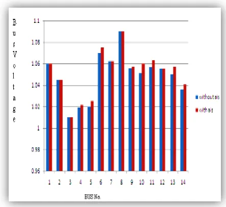
Fig.4 IEEE 14- Bus system voltages
Create antibodies i.e, parent elements
randomly
Introduce an antigen which is near to
antibodies that are generated
Calculate the Euclidean distance
between antibody and antigen
Calculate the affinities and clone the
antibody which is having highest affinity
and replace the antibody with antigen.
Enter each bus voltages and power
values of IEEE buses.
Calculate the fitness at each bus.
Replace the antibodies with mutated
antigens and run the Newton raphson
loadflow with updated busdata
Form the reduced jacobian matrix and
find the eigen values and eigen
vectors for each bus
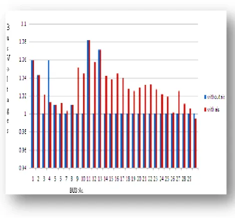
Fig.5 IEEE 30- Bus system voltages
Table1: Participation factor values for IEEE 14 bus system
Bus no.
With AIS
Without
AIS
4
0.0799
0.1325
5
0.1286
0.1806
7
0.3136
0.3613
9
0.0215
0.0282
10
0.1995
0.2499
11
0.0132
0.0382
12
0.2475
0.2968
13
0.3115
0.3607
[image:4.595.344.514.71.273.2]14
0.3286
0.3796
Table 2: Participation factor values for IEEE 30 bus system
Bus no.
With
AIS
Without
AIS
3
0.0106
0.1111
4
0.1164
0.033
6
0.0589
0.0395
7
0.013
0.3201
9
0.2916
0.0031
10
0.0474
0.0055
12
0.0554
0.0933
14
0.0116
0.0809
15
0.0882
0.0022
16
0.0284
0.0128
17
0.1877
0.0681
18
0.0131
0.1402
19
0.0815
0.2413
20
0.0045
0.1719
21
0.0451
0.1278
22
0.1054
0.1868
23
0.0355
0.1046
24
0.2167
0.0049
25
0.1791
0.3045
26
0.035
0.0218
27
0.0194
0.0669
28
0.1512
0.009
29
0.0099
0.1476
30
0.3
0.3377
Table 3: Bus voltages for IEEE 14 bus system
Bus No.
General
AIS
1
1.06
1.06
2
1.045
1.045
3
1.01
1.01
4
1
1.0217
5
1
1.025
6
1.07
1.075
7
1
1.0623
8
1.09
1.09
9
1
1.0576
10
1
1.0598
11
1
1.063
12
1
1.0551
13
1
1.0572
[image:4.595.62.297.72.289.2] [image:4.595.79.253.558.760.2]Table 4: Bus voltages for IEEE 30 bus system
6.CONCLUSIONS
Hence in this paper it is found that by using AIS the bus voltage stability is improved and the bus losses are reduced. The weakest buses of the system are found by developing Modal analysis in MATLAB environment. And it is proved that AIS will give better performance in voltage stability and losses reduction than the conventional methods. By using AIS technique the weakest bus is found and participation factors are reduced when compared with conventional method.
7. REFERENCES
[1] Sharma and Chandrbhan “Determination of power system voltage stability using modal analysis”, IEEE conference Power Engineering, Energy and Electrical Drives, 2007. POWER ENG 2007. International Conference. pp 383,384
[2] Nelson Martins “Overview of Numerical Algorithms for Small Signal Stability Analysis and Control Design” technical review, 2004 pp1-2.
[3] H.R. Bagahee, M. Jannati, B. Vahidi, S.H Rasteger, IEEE conference “Improvement Of Voltage Stability And Reduce The Power Losses optimal GA-Based Allocation Of Multi Facts Devices” 2008 pp2-3 [4] Milad Khaleghi, Malihe M. Farsangi, Hossein
Nezamabadi-pour, and Kwang Y. Lee, “Voltage Stability Improvement By Multiobjective Placement Of SVC Using Modified Artificialimmune Network Algorithm” 2009,IEEE conference, pp 3-5
[5] “Artificial Immune Systems” by Julie Greensmith, Amanda Whitbrook and Uwe Aickelin pp 1-4
[6] J.R. Al-Enezi, M.F. Abbod & S. Alsharhan “Artificial Immune Systems Models, Algorithms And Applications” pp 118-120, May 2010.
[7] S. I. Suliman, T. K. Abdul Rahman, I. Musirin ”Artificial Immune-Based ForVoltage Stability Prediction In Power System” , AIML 06 International Conference, 13 – 15 June 2006 pp 42-43.
[8] Ying Wu Colin Fyfe, Research Paper, “Exploratory data analysis with Artificial immune systems” 26th April,2008
[9] Power Engineering Society Summer Meeting, 2002, pp. 745-752.
[10]IEEE/CIGRE Joint Task Force on Stability Terms and Definitions, “Definition and Classification of Power System Stability”, IEEE Transactions on Power Systems, Vol. 5, No. 2, May 2004, pp. 1387–1401.
[11]J.R. Al-Enezi, M.F. Abbod & S. Alsharhan “Artificial Immune Systems Models, Algorithms And Applications” pp 118-120, May 2010.
[12]S. I. Suliman, T. K. Abdul Rahman, I. Musirin ”Artificial Immune-Based ForVoltage Stability Prediction In Power System” , AIML 06 International Conference, 13 – 15 June 2006 pp 42-44.
[13]F. Dong, B. H. Chowdhury, M. Crow, L. Acar, “Cause and Effects of Voltage Collapse-Case Studies with Dynamic Simulations”, IEEE Power Engineering Society General Meeting, 2004, pp. 1806-1812.