http://dx.doi.org/10.4236/jgis.2014.65036
How to cite this paper: Spivak,L., Spivak, I., Sokolov, A. and Voinov, S. (2014) Comparison of Digital Maps: Recognition and Quantitative Measure of Changes. Journal of Geographic Information System, 6, 415-422.
http://dx.doi.org/10.4236/jgis.2014.65036
Comparison of Digital Maps: Recognition
and Quantitative Measure of Changes
Lev Spivak1, Ivan Spivak2, Alexey Sokolov1, Sergey Voinov3 1Dubna International University, Moscow Region, Russia
2Real Geo Project, Moscow Region, Russia
3University of Applied Sciences, Stuttgart, Germany
Email: [email protected], [email protected], [email protected], [email protected]
Received 21July 2014; revised 18August 2014; accepted 12September 2014
Copyright © 2014 by authors and Scientific Research Publishing Inc.
This work is licensed under the Creative Commons Attribution International License (CC BY). http://creativecommons.org/licenses/by/4.0/
Abstract
A new methodology of comparing digital raster maps was proposed which allows not only detect-ing changes in the maps, but also obtaindetect-ing quantitative measures of the importance of selected differences. Procedure of object interpretation of satellite images and forming of OMT (Object Map of Territory) is described. A list of allowable differences between two OMTs is defined. Two steps technique of quantitative measuring is proposed. At the first stage functions are constructed for calculating local measures of differences in the amount, areas and locations of objects on the map, as well as relations between the objects. In the second stage local measures are used to calculate the integral measure in order to get generalized assessment of difference between maps. The methods for constructing functions which calculate local and integral measures of differences are described. Examples of comparing and measuring the differences between OMTs are provided. Obtained results by utilizing this technique can be used to analyze trends, forecast of development and might be helpful for choosing most efficient scenarios for sustainable spatial planning and land management.
Keywords
Maps Comparison, Object Map of Territory, Change Detection, Local Measure of Difference, Integral Measure of Difference, Sustainable Spatial Planning and Land Management
1. Introduction
416
this task is to compare descriptions of the same territory for different points of time. Maps are traditionally used as territory descriptions for different scales. Nowadays, the most effective solutions for storing, processing and visualizing maps are based on Geographical Informational Systems (GIS). All popular GIS like ArcGIS, qGIS, MapInfo, AutoDesketc, are able to solve very wide range of tasks, but in matter of map comparison they are very limited. Although “change detection” function, which is often included in image and remote sensing data processing software, is able to detect pixels which differ by spectral characteristics, it cannot provide the mean-ing of these changes. Therefore creation of appropriate methodology for map comparisons might be useful con-tribution in this field. Proposed in this paper methodology allows to detecting changes as well as quantitatively assessing the meaning of detected changes. Methodology based on ideas is presented in [3] [4].
2. Comparison of Digital Maps
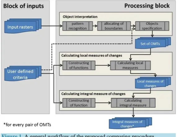
Comparing maps utilizing proposed in this paper approach must be formed appropriate way. Therefore a three- step methodology of creating OMTs is described besides comparing techniques itself. A general workflow of entire process illustrated inFigure 1.
Block of inputs consist of raster imagery, which used as a source for creation OMTs, and user defined data,
such like object specifications and specific criteria’s for constructing measuring functions.
Processing block. Object interpretation section is responsible for creation of OMTs and described in the next
subsection. Calculating of local and integral measures is the main part of this work, which presented in the sec-ond section of this chapter.
2.1. Methodology of Creating Maps of Territory Objects
As a source data for creating maps can be used contact as well as remotely sensed data. The procedure of creat-ing maps based on remote senscreat-ing data called “thematic interpretation”. In the fact, it is necessary to distcreat-inguish object and parametric interpretations. Object interpretation means extraction of borders of objects that corre-sponds to a certain classes on the surface—classification by object types, when parametric interpretation means extracting quantitative values of object properties (land cover characteristics) based of EO data. Note, result of object interpretation is supported with scale of names, but result of parametric interpretation is supported with absolute scale [5].
[image:2.595.171.457.469.690.2]Generally, in the task of object interpretation it is contemplated to transit from digital image1 of observing ter-ritory T, which represented by matrix of pixels
{
F x y(
i, i)
;i=1,, ;n j=1,,m}
with size of δ( )
x y, andFigure 1. A general workflow of the proposed comparing procedure.
1In the common case there could be several images with different time of acquisition, spatial resolution and spectral ranges. Important is that
417
brightness/gray value f x y
(
i, j)
, to its representation as a system of spatial objects{
Т kk: =1,,K}
belonging to different classes with sizes of ∆k(
Х Yk, k)
and relations of R. Note, δ( )
x y, < ∆k(
X Yk, k)
, аN M× K.The result of object interpretation is digital raster map, which we will call in further steps “Object Map of Territory” (OMT). Objects in OMT should meet following conditions:
1) Every object Tk is a set of connected pixels
{
1(
1, 1)
; ;(
,)
}
k k k k k k k δ x δy δMk xMk yMk
∆ = ;
2) All pixels of object Tk are belong to the same land cover class, i.e. Р
( )
δ =pk Idq for all p=1,,Mk. The value of predicate P is ID number of class taken from the list defined by object classifier Id{
Id :q 1, ,}
q Q = = ; 3) 1 K k к Т T = =
, i.e. set of all objects covers entire territory T;4) Тk1
Tk2=0 for all k1, k2 1,= ,K; k1≠k2, i.e. objects does not have common pixels.Before doing object interpretation it is necessary to build object classifier and spectral signatures, which will define criteria for classifying pixels (e.g. Land cover classification system (LCCS)). The object classifier used as a legend for OMT.
The task of object interpretation is similar to image segmentation [6] and as a matter of fact adds up to zoning of territory [3]. In the fact, any result of zoning of territory is OMT.
In the common case, object interpretation task and creating OMT includes three main steps.
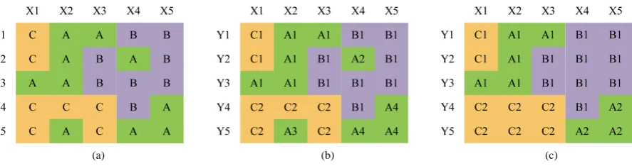
At the first step a classical pixel-based pattern recognition problem has to be solved, where every pixel as-signed to the name of corresponding class. This procedure is similar to the coloring the cell sheet from a note-book. Each object class is painted a special color. Result of this operation is base matrix of OMT (see Figure 2(a)).
In the second step, the boundaries and contours of objects are allocated. As a result, the elements of base ma-trix acquired unique compound names <class name + object name> (seeFigure 2(b)).
In the last step, the contours of objects specified with additional conditions and limitations, in particular to the spatial dimensions of the objects. The output is a final product OMT (seeFigure 2(c)).
OMT formed for a certain point of time and allows formulizing following facts and statements:
1) Within the territory T there are K objects of different classes
{
Т kk: =1,,K}
. List of classes is defined by the classifier (legend) Id={
Id :q q=1,,Q}
.Figure 2(c) presented objects of three classes {A, B, C}.2) Single objects 1, , , 2
q q q
Kq
Т Т Т belongs to Idq class, where Id
{
1, 2, ,}
q q q q
Kq
Т Т Т
= . In our example
class A has two objects, class B—one and class C has two, i.e. А = {А1, А2}; B = {B1}; C = {С1, С2}.
3) Spatial allocation of object Тk defined by set of connected pixels.
(
,)
{
1(
1, 1)
; ;(
,)
}
k X Yk k k δk xk yk δMk xMk yMk
∆ = ∆ . InFigure 2(c) object C1 consists from two pixels and object
A2 from three, i.e. С1 = {(X1, Y2); (X1, Y2)} and А2 = {(X5, Y4); (X4, Y5); (X5, Y5)}.
4) Area of single object Тk equals s
( )
Тk . Sum of areas of all objects of class Id qequals Sq = ∑qs
( )
Тkq . Area can be measured by number of pixels as well as by metric units. InFigure 2(c), object A1 has area of 5 pixels and area of A2 - 3. The sum of object areas of class A equals 8 pixels.5) Objects Тk1 and Тk2 has relation R. Generally, binary relation R defined by pairs of objects, i.e.
(
)
{
k1, k2 : 1, 2 1, ,}
R= Т Т k k = K , which meet the condition R
(
Т Тk1, k2)
=TRUE. The component consistence of binary relations can be set up by list of pairs or by adjacency matrix.Set of relations R often plays important role in describing the current status of territory T. Special importance
[image:3.595.94.538.576.693.2]
(a) (b) (c)
takes relation of type “neighbor”, which defines set of object pairs having common border. In particular, relation of type “neighbor” from OMT, shown inFigure 2(c), has six pairs of objects: {(А1, В1); (А1, С1); (А1, С2);
(А2, В1); (А2, С2); (В1, С2)}. Corresponding adjacency matrix illustrated below.
Neighbor А1 А2 B1 С1 С2
А1 0 0 1 1 1
А2 0 0 1 0 1
B1 1 1 0 0 1
С1 1 0 0 0 0
С2 1 1 1 0 0
Note, adjacency matrices of binary relations are always symmetrical. This can be used in order to reduce amount of memory for their storage.
2.2. Comparison of OMTs and Quantitative Assessment of Changes
To detect changes it is necessary to compare OMTs corresponding to sequence of times. OMT of territory T for the point of time t we will call OMT
( )
Tt .The comparison is based on the following scheme:
( )
(
)
(
( )
)
{
Before OMT Tt1 → After OMT Тt2}
.Of course, in order to detect changes correctly, comparing OMTs must have the same pixel size and spatial extend. If these conditions are met, two comparing OMTs will have a finite number of valid types differences as listed inTable 1.
Detection of changes is only half the story. Practically, the most important thing is to differentiate detected changes between important ones and not important ones. For quantitative assessment and ranking changes it is necessary to have some special criteria and functions which allow calculating the measure of differences.
Note, it is not possible to construct one universal function to compare maps with different content. Further-more, for every special situation it might be necessary to construct specific measuring functions which are de-pends on specifics of observing area and task.
When comparing maps it is necessary to distinguish integrated and local measuring functions [4]. Local func-tions allows to measure some specific changes (shown inTable 1), when integral ones can measure general dif-ference of maps.
In order to measure local differences it is necessary to construct local measuring functions for the following measures:
λ1—measure, for changes in number of classes;
Table 1. List of possible changes when compared two OMTs.
What has been changed Was: OMT (Тt1) Became: OMT (Тt2) Type of change
Number of object classes
{
Id : 1, , 1}
q
t
q= Q . {Id : 1, , 2}
q
t
q= Q Qt1≠Qt2
Number of objects of current class { : 1, , 1}
q q
k t
Т k= K { : 1, , 2}
q q
k t
Т k= K q1 q2
t t
K ≠K
Spatial allocation of object t1( t1, t1)
k Xk Yk
∆ 2( 2 2)
,
t t t k Xk Yk
∆ t1 t2
k k
∆ ≠ ∆
Area of current object st1( )Тk st2( )Тk st1( )Тk ≠st2( )Тk
Sum of areas of all object of certain class 1 1
( )
q q
t q t k
S =
∑
s Т 2 2( )
q q
t q t k
S =
∑
s Т 1q q2t t
S ≠S
419
λ2—measure, for changes in number of objects of different classes;
λ3—measure, for changes in areas of objects of different classes;
λ4—measure, for changes in spatial allocation of objects;
λ5—measure, for changes in relations between objects.
Measurement of λ1, λ2 and λ3 presents no special difficulties, corresponding procedures are described in [4]. To measure λ4 it is possible to use operational approach proposed in [3]. It involves determining the number and “cost” of operations required to convert the situation “was” to “became”. Every operation allows you to convert class of a single pixel. “Cost” of operations can be specified using the corresponding adjacency matrix of object classes. In particular, such matrix for OMT fromFigure 2(c) will have following form:
Became
Was А В С
А 0 γ12 γ13
В γ21 0 γ23
С γ31 γ32 0
In the common case “cost” matrix is not symmetrical. For example, transformation of forest into the field will have higher cost than another way around, therefore λ4 OMT ,
(
1 ОMT2)
≠λ4 OMT ,(
2 ОMT1)
.If all pixels of OMT have the same “cost”, measure of difference between two lines (of images) can be calcu-lated using following formulation:
(
1 2)
4 line OMT , line ОMT i j ij ij i 1, , ; Q j 1, , ; Q i j
λ = ∑ ∑ γ ρ = = ≠ (1)
where:
ij
ρ —number of operations, that necessary to convert objects of class i into objects of class j;
ij
γ —“cost” of corresponding operation.
The final (total) local measure λ4 (OMT1, OMT2) calculated by summing of measures of individual lines. Additional difficulties when calculating λ4 may arise due to dependency of operation cost from pixel position in the base matrix. For example, conversion of the central pixels might cost more than peripheral ones. Further-more, each pixel may have its own weight, defined by its location on the map. In such case it is necessary to de-fine a weight matrix of conversion for all pixels in the source map for every operation.
2.2.1. Measurement of Relation Changes between Objects
When measuring relation changes it is necessary to consider differences in number of relations as well as its consistency. This means:
(
1 2)
1 25 OMT ,ОMT 5 5
λ =λ +λ (2)
where:
λ51—measure of number of changes;
λ52—measure of consistence of changes.
Strictly speaking, the whole list of relations (classifier) as well as classifier of objects should be defined on the phase of forming of OMT (3 stages) and should not be changed further. In case of changes in forming OMT phase, corresponding changes in measuring functions should be applied as well.
Changes in component consistency are based on changes in spatial allocation and quantity of objects. If con-sistence of relations defined by list of object pairs, then as changes would be considered adding or deleting such pairs. For every relation the “cost” of adding or deleting of objects pairs might be different. In case if the “cost” is always the same or constant, then total “cost” can be calculated using following formulation:
(
)
2 1 2
5 OMT ,ОMT i i i i
λ =β ω γ υ+ (3)
where: i
β —weight (cost) of adding new object pair into i relation; i
ω —number of added object pairs into i relation; i
i
υ —number of object pairs deleting from i relation.
In case of non-constant “cost” of adding/deleting of object pairs provided formulation should be modified correspondingly.
2.2.2. Integral Measure
Local measure used to construct integral measure. In simple case, integral measure can be formulated by linear combination of local measures
(
OMT ,1 ОMT2)
δ λ δ λ1 1 2 2 δ λ3 3 δ λ4 4 δ λ5 5Λ = + + + + (4)
where, δi—weight of local measure.
Maps with small integral measures of differences should be considered as similar.
If local and integral measures are above defined thresholds, then detected changes recognized as “significant” and considered for further analysis. Calculated quantitative measures can be further used to analyze trends, forecast of development and might be helpful for choosing most efficient scenarios for sustainable spatial plan-ning and management.
When comparing maps, which are sequential in time, the cumulative effect of small changes should be con-sidered. In particular, the differences between two maps—the previous and current can be low (below the threshold), but if we compare maps corresponding to the beginning and to the end of a large time interval, the differences may be significant.
3. Example of OMT Comparison
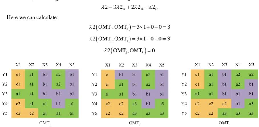
As an example we will compare three OMT which illustrated inFigure 3.
Given that the number of classes does not vary, as an integral measuring function we take
2 2λ λ4 3 5λ
Λ = + +
Let’s assume that adding/deleting of object pairs has a constant “cost”. In this case local measure of differ-ences for number of objects would have following formulation:
2 Sq q 2q λ = α λ
where:
2q
λ —local measure of differences in number of objects of q-class;
q
α —weight for objects of q-class.
In our case, measuring function λ2 can have following formulation:
А В С
2 3 2 2 2 2
λ = λ + λ +λ
Here we can calculate:
(
1 2)
2 OMT ,ОMT 3 1 0 0 3
λ = × + + =
(
1 3)
2 OMT ,ОMT 3 1 0 0 3
λ = × + + =
(
2 3)
2 OMT ,ОMT 0
λ =
[image:6.595.85.540.479.702.2]
421
To calculate λ4 we will use operational approach, allowing us indirectly assess changes in object areas. In or-der to simplify our task we will assume that “cost” of transformation is the same for all pixels and adjacency matrix is similar and looks like shown below.
Became
Was А В С
А 0 10 8
В 10 0 6
С 8 6 0
As a result we will get following measures:
• λ4 OMT ,
(
1ОMT2)
=10 8 18+ =• λ4 OMT ,
(
1 ОMT3)
=10+ × =2 8 26• λ4 OMT ,
(
2 ОMT3)
= × + =2 10 8 28To calculate λ5, we have to form lists of relations “neighbor”:
• R
{
OMT1} (
={
А1,С1 ; А1,В1 ; А1,С2 ; А2,В1) (
) (
) (
)
}
• R
{
OMT2} (
={
А1,С1 ; А1,В1 ; А1,С2 ; А2,В1 ; А3,В1 ; А3,С2) (
) (
) (
) (
) (
)
}
• R
{
OMT3} (
={
А1,С1 ; А1,В1 ; А1,С2 ; А2,В1 ; А3,В1 ; А3,С2) (
) (
) (
) (
) (
)
}
We already agreed that “cost” of adding/deleting of object pairs is constant. If we take as a “cost” value of 5, we can calculate following measures:
• λ5 OMT ,
(
1 ОMT2)
= × =2 5 10• λ5 OMT ,
(
1 ОMT3)
= × =2 5 10• λ5 OMT ,
(
2 ОMT3)
=0Finally, we can calculate integral measures of differences:
(
ОMT ,ОMT1 2)
2 3 18 3 10 54Λ = × + + × =
(
ОMT ,ОMT1 3)
2 3 26 3 10 62Λ = × + + × =
(
ОMT ,ОMT2 3)
2 0 28 3 0 28Λ = × + + × =
It is clear that difference between OMT2 and OMT3 is significantly lower than difference between OMT1 and OMT3. Particularly, if OMT3 is desirable substance and OMT1 and OMT2 are alternative scenarios, then we can select OMT2 because it is closer to our goal.
4. Conclusions and Recommendations
1) Developed methodology allows obtaining quantitative measures of differences between pairs of Object Maps of Territory based on five different measures of changes:
λ1—number of classes;
λ2—number of objects of different classes;
λ3—areas of objects of different classes;
λ4—spatial allocation of objects;
λ5—relations between objects.
2) Approaches to calculating local and integral measures of differences are proposed. In the simplest case, the integral measure of changes can be formulated as linear combination of local measures.
3) One of the most important problems in calculating of integral measures is to define appropriate weights. There is no common rule for solving this problem. It always depends on task and maps content.
Based on provided methodology, it is planned to develop GIS techniques for analysis of time series maps. Furthermore, a handbook describing ways to apply approach for decision makers in accordance with the work-flow <description of the current status → recognition of changes → trend analysis → forecast → choice of con-trol actions> will be compiled. A handbook will include recommendations for constructing of measuring func-tions for comparing OMT.
References
[1] Cheremisina, E.N., Spivak, L.F. and Spivak, I.L. (2013) Information and Analytical Tools of Situational Center of Ter-ritory Control. Geoinformatica, 3, 1-7.
[Черемисина, Е.Н., Спивак, Л.Ф., Спивак, И.Л. (2013) Информационно-аналитическое обеспечение ситуационного центра управления территорией. Геоинформатика, 3, 1-7.]
[2] Cheremisina, E.N. and Spivak, I.L. (2011) Conceptual Bases of Development of the Automated Management Systems for Territories. Geoinformatica, 4, 14-17.
[Черемисина, Е.Н., Спивак, И.Л. (2011) Концептуальные основы построения автоматизированных систем управления территориями.Геоинформатика, 4, 14-17.]
[3] Voronin, Yu.A. and Spivak, L.F. (2004) Theory of Zoning and Management of Territories. SO RAN, Novosibirsk, 230 p.
[ВоронинЮ.А., СпивакЛ.Ф. (2004) Теория районирования и управление территориями.Новосибирск: Изд-во СО РАН, 230с.]
[4] Spivak, L.F. and Spivak, I.L. (2010) Method of Quantitative Evaluation of Mapschanges. Geoinformatica, 2, 41-46. [Спивак, Л.Ф., Спивак, И.Л. (2010) Методика количественной оценки изменений картографических результатов мониторинга. Геоинформатика, 2, 41-46.]
[5] Spivak, I.L. (2010) Thematic Interpretation Tasks in Space Monitoring Systems. Geoinformatica, 4, 61-65.
[Спивак, И.Л. (2010) Задачи тематического дешифрирования в системах космического мониторинга.
Геоинформатика, 4, 61-65.]
[6] Gonzales, R.S. and Woods R.E. (2002) Digital Image Processing. Prentice Hall,Upper Saddle River, 567 p.
Nomenclature
OMT Object Map of Territory
GIS Geographical Informational Systems EO Earth Observation
LCCS Land Cover Classification Systems
λ1 measure of changes in number of classes
λ2 measure of changes in number of objects of different classes
λ3 measure of changes in areas of objects of different classes
λ4 measure of changes in spatial allocation of objects