Design of Real Time Data Acquisition with Multi Node
Embedded Systems
Mukesh Kumar
Lovely Professional UniversityPunjab, India
Sanjeev Sharma
Lovely Professional UniversityPunjab, India
Mansav Joshi
Punjab Technical UniversityPunjab, India
ABSTRACT
This paper is about the application of data acquisition systems in industrial requirements for real time execution of events with industrial process control and automation. Multiple embedded nodes are measuring various industrial parameters to monitor and control industrial process. Data acquired from each node is processed, displayedand sent to master processor (CPLD XC9572) that compile data received from different nodes and send this information to remote location using GSM technology and simultaneously display the variations in quantity under measurement to local and remote system configured with LabVIEW platform. In addition, the master processor process this information and generates controls signals based on predefined cases or can receive the controlling action from remote controller to control the industrial application like CNC machines, Electric drives etc. The paper adds the value towards the low cost, less manufacturing time, ease of implementation with reliable measuring, controlling and data logging demands of industry.
General Terms
Master node, Slave node, Data acquisition, Real time
Keywords
ADC, LabVIEW, Microcontroller, CPLD.
1.
INTRODUCTION
At present DAQ systems are widely popular in industry in the control and remote monitoring of system status and physiological parameters. Data AcQuisition refers to acquiring data in form of physical quantity or time varying quantity and performing A\D conversion, then display or log acquired data for future reference and analysis. Complex programmable logic device (CPLD) is programmable digital logic devices, which are simpler devices for programming digital logics and functions. For writing firmware programming to the equipment, VHDL, Embedded „C‟, LabVIEW graphical programming is used.
2.
DESIGN OF REAL TIME DATAACQUISITION SYSTEM
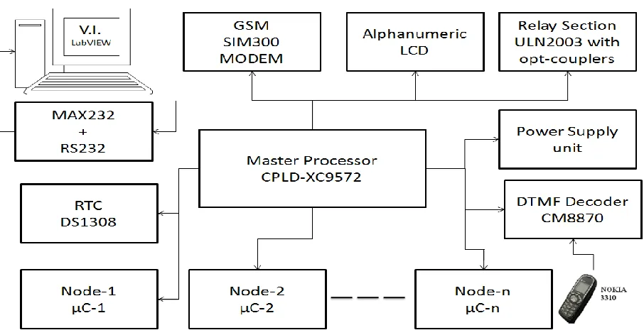
[image:1.595.76.529.486.722.2]Design of data acquisition system is demonstrated for measurement of parameters like moisture, temperature, light, humidity etc. by acquiring data using different sensors at different locations and communicating with the user using DTMF and GSM module. System description divided into two parts, consisting of hardware and Software description.
2.1
SOFTWARE DESCRIPTION
Xilinx-IDE and Keil μVision-3 is being used to design program codes for master and slave nodes, to read, monitor and display process parameters for real time data acquisition system. After creating hex files for microcontroller nodes, functionalities of the system tested on Proteus 7.4 SP3 advanced simulator and then hex files programmed into microcontroller by using universal programmer kit. The programming and simulation for master node (XC9572) has done with VHDL in Xilinx-IDE.
2.2
HARDWARE DESCRIPTION
In the design of real time data acquisition system, we used several sensors like LDR, temperature sensors, Rain sensors and soil sensors that will observe the different parameters. The ADC for receiving the analog input and converts it into digital data that will be process by Slave controller. We have used Xilinx XC9572 CPLD as master processor. We are using master and slave method for realization of this multi-node DAQ system. For slaves we have used 8-bit microcontroller name 89C52. The slave takes the decision as per instruction stored in its program memory and display the result on 16x2 LCD. The signal can be sent at faraway places by using GSM module through CPLD and display waveforms of acquired signals on front panel designed with LabVIEW. Apart from this, DTMF receiver section integrated with this system for device control.
2.2.1
Microcontroller
[image:2.595.346.502.159.316.2]Microcontrollers are small and cost effective but self-contained computer chips used for embedded applications in industrial and consumer electronics products. In this system, we are using AT89C52 microcontroller as slaves and XC9572 as master processor.
Fig 2: Schematic for AT89C52 for Slave Nodes
The slave controllers are receiving the data from different sensors, placed at specific locations and sending the data to master processer that communicating with the user. Outputs of the sensors can be provided to master processer directly but in this case, distance is the constraint, means sensors can‟t be placed at far distance from the master processor but by using
different slave controllers we can access the different sensors placed at different places and values can be send to master processor from slaves through different means.
2.2.2
Liquid Crystal Display
In this system, master and slave nodes connected to 16x2 LCD, to display the measured physical quantities.
[image:2.595.34.283.444.654.2]Fig 3: Schematic for 16x2 LCD
2.2.3
Microcontroller Nodes for measurements of
process parameters
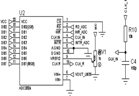
To demonstrate performance of real time data acquisition system with multiple nodes, we have demonstrated common sensor applications like temperature, light, soil moisture, rain, water level measurements. For this purpose analog to digital conversion technique used to acquire equivalent electrical signal into binary for calibration of various process parameters or physical quantities.
Fig 4: Schematic for ADC0804 (Single channel ADC) for Analog to Digital Conversion
2.2.4
Temperature Measurement
[image:2.595.314.554.447.613.2]Fig 5: Schematic for LM35 IC temperature measurement
2.2.5
Light intensity measurement
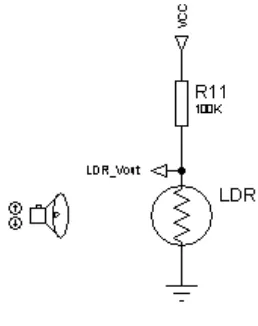
[image:3.595.320.525.70.229.2]A simple light intensity sensor can be constructed using light depended resistance (LDR) to measure the light, it will show different status of light based on the intensity of the light. When light intensity is very low it will show the status darkness or night, when intensity is dim it will show dim, when intensity is medium it will show normal status and for the high intensity it will show day or brightness on LCD.
Fig 6: Schematic for LDR for Light measurement
2.2.6
Soil moisture measurement
For measurement of soil moisture, simple NPN transistor BC547 in CE configuration is used. We know the collector current is the function of base current, by varying base current, proportionally collector current varies. Variations in collector current acquired by ADC0804 and calibrated in to three levels of soil status i.e. excess, optimum and dry.
2.2.7
Water sensor and Rain sensor
[image:3.595.319.551.71.678.2]A rain sensor or rain switch is a switching device activated by rainfall. NPN transistor BC547 is use as a switch, which is interfaced to microcontroller, when there is no conduction at rain strips connected at base of transistor LCD display status as Rain: OFF otherwise ON during rainfall.
Fig 7: Schematic for Soil measurement
Fig 8: Schematic for rainfall measurement
[image:3.595.85.214.354.517.2] [image:3.595.316.541.431.693.2]2.2.8
Master processor-XC9572
[image:4.595.329.553.71.251.2]The XC9572 is a high-performance CPLD providing advanced in-system programming and test capabilities for general-purpose logic integration, which is desired for our design. It is comprised of eight 36V18 Function Blocks, providing 1,600 usable gates with propagation delays of 7.5 ns. Here XC9572 is used as master processor that acquires information from all the slave nodes and transfer data to user through GSM module as well as display it as waveform on front panel and log into the excel sheet using LabVIEW platform.
Fig 10: Simple package for XC9572 chip
2.2.9
GSM SIM-300 Module Interfacing
SIM300 is a Tri-band GSM/GPRS module that operate on frequencies 900 MHz to 1900 MHz, SIM300 can use in many application, such as Smart phone, PDA phone and other mobile device. The physical interface to the mobile applications made through a 60 pins board-to-board connector, which provides all hardware interfaces between the module and customers‟ boards except the RF antenna interface.
SIM300 Specifications:
Two serial ports to interface with Microcontrollers or PCs
Two audio channels include two microphones inputs and two speaker outputs.
This can easily configure by AT command.
SIM300 provide RF antenna interface with two alternatives: antenna connector and antenna pad.
The SIM300 is designed with power saving technique, the current consumption to as low as 2.5mA in SLEEP mode.
The SIM300 integrated with extended TCP/IP AT commands.
2.2.10
Real time clock DS1308
[image:4.595.54.277.191.333.2]The DS1308 Serial Real Time Clock is a low power, full BCD clock/calendar plus 56 bytes of nonvolatile SRAM. Address and data transferred serially via a 2–wire bi–directional bus. The clock/calendar provides seconds, minutes, hours, day, date, month, and year information.
Fig 11: GSM Module SIM-300
The end of the month date automatically adjusted for months with less than 31 days, including corrections for leap year. The clock operates in either the 24–hour or the 12–hour format with AM/PM indicator. The DS1308 has a built–in power sense circuit that detects power failures and automatically switches to the battery supply.
2.2.11
UART interfacing with LabVIEW platform
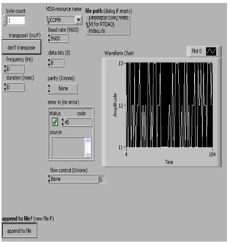
Universal asynchronous receiver transmitter used here to interface computer through 9-pin RS232 port to display acquired signal waveform with front panel of LabVIEW platform. The LabVIEW front panel designed for user interface to display waveforms of measured physical quantities, control number of byte counts, setting baud rate, selection of communication port number i.e. VISA resources name, error control techniques etc. The programming in LabVIEW is graphical programming and performs in block diagram as shown in Fig.12 and 13.
[image:4.595.314.546.450.696.2]Fig 13: Block diagram for graphical programming in LabVIEW for real time data acquisition and logging
system
2.2.12
Device control with dual tone multiple
frequency decoder
User can take decisions to automate/control any process through device automation by calling data acquisition system with mobile, selection of device to automate/control is decoded with DTMF decodes MT8870 at receiver site. The MT8870D is a complete DTMF receiver integrating both the band split filter and digital decoder functions. The filter section uses switched capacitor techniques for high and low group filters; the decoder uses digital counting techniques to detect and decode all 16 DTMF tone-pairs into a 4-bit code. AC devices/drives are ON/OFF through electromechanical switch called 12-volt DC relay with ULN2003.
3.
RESULTS
AND
DISCUSSIONS
[image:5.595.342.519.87.692.2]The system has been implemented, tested successfully and achieved reliable transmission of data to the remote site and representation of waveform along with logging of data in excel sheet using LabVIEW.
[image:5.595.45.282.567.726.2]Fig 14: Actual hardware implemented for real time data acquisition with multi node embedded systems
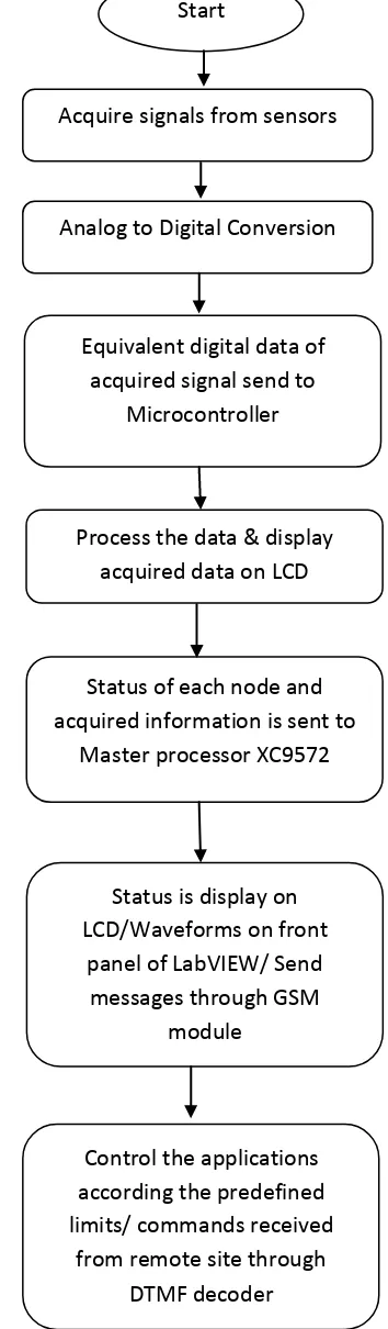
Fig 15: Flow chart for real time data acquisition system with multi-node embedded systems
Start
Acquire signals from sensors
Analog to Digital Conversion
Equivalent digital data of
acquired signal send to
Microcontroller
Process the data & display
acquired data on LCD
Status of each node and
acquired information is sent to
Master processor XC9572
Status is display on
LCD/Waveforms on front
panel of LabVIEW/ Send
messages through GSM
module
Control the applications
according the predefined
limits/ commands received
Fig 16: LCD display connected with master processor
[image:6.595.45.276.313.409.2]Fig 17: LCD display connected with node for temperature measurement
Fig 18: LCD display connected with node for light intensity measurement
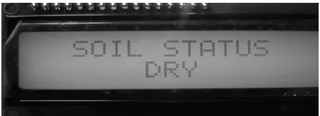
Fig 19: LCD display connected with node for soil moisture measurement
Fig 20: LCD display connected with node for rainfall and water level measurement
4.
CONCLUSION
In this paper, master-slave architecture for real time data acquisition and logging is demonstrated and
implemented. Multiple embedded nodes are measuring
various industrial parameters to monitor and control industrial process. Acquired data display at each node and sent to master processor that compile the acquired information and send to remote location using GSM technology and simultaneously display and log into spreadsheet the variations in quantity under measurement to local and remote system configured with LabVIEW platform. In addition, the master processor processes this information and generates controls signals based on predefined cases or can receive the controlling action from remote controller to control the industrial application. The paper adds the value simple approach for data acquisition, continuous monitoring of process parameters, less manufacturing time, ease of implementation with reliable measuring, controlling and data logging demands of industry.
5.
ACKNOWLEDGMENT
I hereby express my gratitude to my colleagues for their support in system design and verification.
6.
REFERENCES
[1] Mukesh Kumar and Mansav Joshi, Design and Implementation of Embedding Web Server for Real Time Data Acquisition and Logging System, 4th International Conference on Computer and Automation Engineering (ICCAE 2012), Mumbai, India, January 14-15, 2012.
[2] Li Bing and Sun JianPing, "Remote Video Monitoring System Based on Embedded Linux and GPRS", Proceedings of the 2nd International Conference on Computer Engineering and Technology 2010 volume 3. [3] Nation Instruments, "LabVIEW Reference Manual",
USA, 2010.
[4] Ying-Wen Bai and Cheng-Yu Hsu, "Design and Implementation of an Embedded Remote Electronic Measurement System",Proceedings of the IMTC 2006 – Instrumentation and Measurement Technology Conference Sorrento, Italy 24-27 April 2006.
[5] K. Rangan and T. Vigneswaran, An Embedded System Approach to Monitor Green House, 978-1-4244-9182-7/10 2010 IEEE.
[6] Matt Matoushek, Internet Data Acquisition,2nd IEEE International Conference on Space Mission Challenges for Information Technology, 2006.
[7] Keil-Embedded Development Tools, ARM Germany GmbH.
[8] Proteus Professional 7, Labcenter Electronics, England. [9] AT Commands Set, SIM300_ATC_V1.06, SIM Com
2006.
[image:6.595.44.273.458.541.2] [image:6.595.39.276.596.683.2][11] XC9572 In-System Programmable CPLD, DS065 (v4.3) April 3, 2006.
[12] Jean Paul Talledo Vilela, Student Member, IEEE, Jose Carlos Miranda Valenzuela, Member IEEE,Design and Implementation of a Wireless Remote Data Acquisition System for Mobile Applications, IEEE 2005
[13] Manivannan M and Kumaresan N, Design of On-line Interactive Data Acquisition and Control System for
Embedded Real Time Applications, Proceedings of ICETECT 2011