© 2018, IRJET | Impact Factor value: 6.171 | ISO 9001:2008 Certified Journal | Page 985
Component Measurement Using Ultrasonic Sensor
Karan Sangaj
1, Sudarshan Shinde
2, Aditya Suryawanshi
3, Rameez Shanediwan
4, Apurva Potdar
51,2,3,4,5
UG , Department of Mechanical Engineering , KIT's College of Engineering , Kolhapur , India.
---***---Abstract -
The objective of this project is to design and manufacture the instrument which can measure geometrical parameters (length, width, height) of component without using traditional or current measuring techniques. This instrument has various advantages over the traditional measuring instruments.it has less moving parts and requires less physical efforts to operate it. The instrument consists of most crucial part known as ultrasonic sensor, LCD display, a circuit which is used to control the various components knows as arduino and set of wires.Key Words: Ultrasonic Sensor, Component Measurement, Arduino, Job Inspection, Job Analysis, Job Measurement.
1. INTRODUCTION
An Ultrasonic sensor is a device that can measure the distance to an object by using sound waves. It measures distance by sending out a sound wave at a specific frequency and listening for that sound wave to bounce back. By recording the elapsed time between the sound wave being generated and the sound wave bouncing back, it is possible to calculate the distance between the sonar sensor and the object. Since it is known that sound travels through air at about 344 m/s (1129 ft/s), you can take the time for the sound wave to return and multiply it by 344 meters (or 1129 feet) to find the total round-trip distance of the sound wave. Round-trip means that the sound wave travelled 2 times the distance to the object before it was detected by the sensor; it includes the 'trip' from the sonar sensor to the object AND the 'trip' from the object to the Ultrasonic sensor (after the sound wave bounced off the object). To find the distance to the object, simply divide the round-trip distance in half. NOTE: The accuracy of Ultrasonic sensor can be affected by the temperature and humidity of the air it is being used in [1]. However, this change in accuracy will be negligible. It is important to understand that some objects might not be detected by ultrasonic sensors. This is because some objects are shaped or positioned in such a way that the sound wave bounces off the object, but are deflected away from the Ultrasonic sensor. It is also possible for the object to be too small to reflect enough of the sound wave back to the sensor to be detected. Other objects can absorb the sound wave all together (cloth, carpeting, etc.), which means that there is no way for the sensor to detect them accurately. These are important factors to consider when designing and programming a instrument using an ultrasonic sensor.
2. INSTRUMENTATION
In instrumentation section we are discussing the main parts used in instrumental setup. Various parts like ultrasonic sensor, LCD display, Arduino board and each one of this part is discussed in detail below.
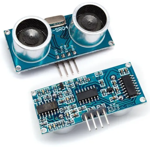
[image:1.595.311.556.267.735.2]2.1 ULTRASONIC SENSOR
FIG 1 : ULTRASONIC SENSOR
[image:1.595.315.558.274.512.2]© 2018, IRJET | Impact Factor value: 6.171 | ISO 9001:2008 Certified Journal | Page 986 WORKING PRINCIPLE
1. Adopt IO trigger through supplying at least 10us sequence of high level signal.
2. The module automatically send eight 40 kHz square wave and automatically detect whether receive the returning pulse signal.
3. If there is signals returning, through outputting high level and the time of high level continuing is the time of that from the ultrasonic transmitting to receiving.
SPECIFICATIONS
1. Working Voltage: 5V (DC) 2. Static current: Less than 2mA.
3. Output signal: Electric frequency signal, high level 5V, low level 0V.
4. Sensor angle: Not more than 15 degrees. 5. Detection distance: 2cm-450cm.
6. Precision: Up to 0.3cm
7. Input trigger signal: TTL impulse
8. Echo signal: output TTL PWL signal Mode of connection
PIN CONFIGRUATION
Pin No Pin Name Description
1 Vcc The Vcc pin powers the
sensor, typically with +5V 2 Trigger Trigger pin is an Input pin.
This pin has to be kept high for 10us to initialize measurement by sending US wave.
3 Echo Echo pin is an Output pin. This pin goes high for a period of time which will be equal to the time taken for the US wave to return back to the sensor.
[image:2.595.311.559.141.252.2]4 Ground This pin is connected to the Ground of the system.
TABLE 1: PIN CONFIGRUATION
2.2
LCD ALPHANUMERIC DISPLAY
A 16x2 LCD means it can display 16 characters per line and there are 2 such lines. In this LCD each character is displayed in 5x7 pixel matrix. it displays black text on green background, Connection port is 0.1" pitch, single row for easy bread boarding and wiring, Pins are documented on the back of the LCD to assist in wiring it up, Single LED backlight included can be dimmed easily with a resistor or PWM and uses much less power than LCD with electroluminescent
[image:2.595.310.558.199.473.2]backlights. It can be fully controlled with only 6 digital lines.it has built in character set which supports most of the English/European/Japanese text, Up to 8 extra characters can be created for custom glyphs or 'foreign' language.
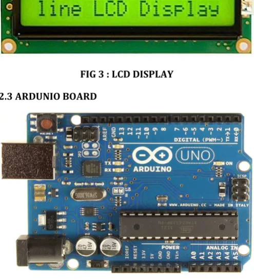
FIG 3 : LCD DISPLAY
2.3 ARDUNIO BOARD
FIG 4 : ARDUNIO BOARD
Arduino board designs use a variety of microprocessors and controllers. The boards are equipped with sets of digital and analog input/output (I/O) pins that may be interfaced to various expansion boards or Breadboards (shields) and other circuits. The boards feature serial communications interfaces, including Universal Serial Bus (USB) on some models, which are also used for loading programs from personal computers. The microcontrollers are typically programmed using a dialect of features from the programming languages C and C++. In addition to using traditional compiler tool chains, the Arduino project provides an integrated development environment (IDE) based on the Processing language project.
SPECIFICATIONS
1. Microcontroller ATmega328P
2. Operating Voltage: 5V
3. Input Voltage (Recommended): 7-12V
4. Digital I/O Pins14 (of which 6 provide PWM output)
[image:2.595.37.287.405.616.2]© 2018, IRJET | Impact Factor value: 6.171 | ISO 9001:2008 Certified Journal | Page 987
3. CALCULATIONS
Distance travelled by sound = speed of sound x time that sound travels
Speed calculations
Speed of sound C= (331.3+0.606v) m/s [2]. Where v is the temperature in degrees Celsius (°C). At 30 °C (assumed)
C=349.48 m/s = 0.34948 mm/microsecond
Time calculations
Time that sound travels = duration (in micro seconds)
Distance calculations
The distance between the sensor and the object is one-half the distance travelled by the sound wave.
Distance between object and sensor = 0.5 x Distance that sound travels
Physical constraints
Offset = 72mm
MODIFIED DISTANCE FORMULA BETWEEN OBJECT AND SENSOR
Substituting values in Distance equation, we get Distance = (0.5 x 0.34948 x duration) -72 Distance = [(0.17474x duration) -72] mm
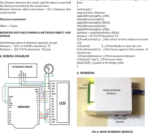
4. WIRING DIAGRAM
FIG 5: WIRING DIAGRAM
5. PROGRAM
#include <LiquidCrystal.h> //Load Liquid Crystal Library LiquidCrystal LCD (11, 10, 9, 2, 3, 4, 6); //Create Liquid Crystal Object called LCD
#define trigPin 13 //Sensor Echo pin connected to Arduino pin 13
#define echoPin 12 //Sensor Trip pin connected to Arduino pin 12
void setup() {
pinMode(trigPin, OUTPUT); pinMode(echoPin, INPUT);
LCD.begin(16,2); //Tell Arduino to start your 16 column 2 row LCD
LCD.setCursor(0,0); //Set LCD cursor to upper left corner, column 0, row 0
LCD.print("Length/Dia/Width"); //Print Message on First Row
}
void loop() {
long duration, distance; digitalWrite(trigPin, LOW); delayMicroseconds(2); digitalWrite(trigPin, HIGH); delayMicroseconds(10); digitalWrite(trigPin, LOW);
duration = pulseIn(echoPin, HIGH); distance = (0.17474*duration)-72;
LCD.setCursor(0,1); //Set cursor to first column of second row
LCD.print(" "); //Print blanks to clear the row LCD.setCursor(0,1); //Set Cursor again to first column of second row
LCD.print(distance); //Print measured distance LCD.print(" mm"); //Print your units.
delay(250); //pause to let things settle }
[image:3.595.37.563.289.756.2]6. WORKING
© 2018, IRJET | Impact Factor value: 6.171 | ISO 9001:2008 Certified Journal | Page 988 FIG 7: MEASURING MODULE
The instrument consists of two modules, first is known as main working module and second is known as measuring module. The main working module and measuring module, both are made of acrylic material. The main working module housing consists of ultrasonic sensor, arduino board, LCD display and set of wires. On measuring module two passages are made to measure diameter/width and length of component. In length measuring passage component is first kept and slider is moved till it touches top of component, then component is removed (component restricts the sound waves passing to slider) and measured value is noted down. Same procedure can be used for measuring diameter/width, but instead of placing component in length passage it is kept in diameter passage. If component have approximately same diameter/width and length, it can be kept in any passage.
7. OBSERVATIONS
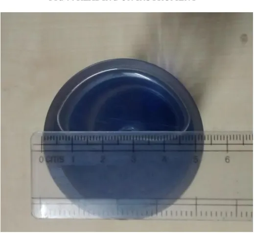
[image:4.595.308.568.221.459.2]7.1 DIAMETER MEASUREMENT
FIG 8: DIAMETER MEASURING
[image:4.595.324.541.514.741.2]FIG 9: READING ON INSTRUMENT
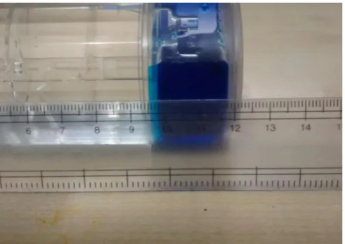
FIG 10: ACTUAL READING ON SCALE
7.2 LENGTH MEASURMENT
[image:4.595.38.539.518.740.2] [image:4.595.34.293.535.725.2]© 2018, IRJET | Impact Factor value: 6.171 | ISO 9001:2008 Certified Journal | Page 989 FIG 12: READING ON INSTRUMENT
FIG 13: ACTUAL READING ON SCALE
8. RESULTS
SR
NO PARAMETER ACTUAL VALUE INSTRUMENT READING
(mm) (mm)
1. Diameter 53 53
2. Length 122 122
TABLE 2: RESULTS
9. ADVANTAGES
1. Various geometrical parameters can be measured on same equipment.
2. No requirement of skilled labor. 3. Time saving operation.
4. Accuracy can be increased using more accurate ultrasonic sensor.
5. Equipment is portable.
10. CONCLUSION
The instrument is portable, convenient and easy to use. From above results it is observed that the original values and measured values are approximately same. We can improve accuracy by using more accurate ultrasonic sensor.
11. REFERENCES
1. “Sound Systems: Design and Optimization: Modern Techniques and Tools for Sound System Design and Alignment” - Bob McCarthy / CRC Press, 2016 .ISBN 1317911091, 9781317911098. Pg.83.
2. “Fundamentals of Physics” - Giambattista / Tata McGraw-Hill Education, 2010.ISBN 0070648506, 9780070648500. Pg.419.