33
NONLINEAR 8/6 SWITCHED RELUCTANCE
GENERATOR EXCITED BY PARTICULAR CONVERTER
1F. MESSAI, 1M. MAKHLOUF, 1H. BENALLA
1Department of Electrical Engineering, Faculty of Engineering Sciences, Mentouri University of
Constantine, Algeria
E-mail : [email protected]
ABSTRACT
This paper describes a consideration of the excitation circuit of a switched reluctance generator (SRG). The SRG is a doubly salient machine. It does not contain any magnets or brushes, and the phases are completely independent. The rotor is made of laminated iron and it does not have any winding. However, the conventional excitation circuit of this machine is an asymmetry half bridge converter (AHBC) whose configuration is complicated. In this paper, we present a nonlinear modeling and simulation of a four phase double salient switched reluctance generator (SRGDS 8/6) excited by a suppression resistor converter (SRC) based on finite-element analysis (FEA) and Matlab/Simulink.
Keywords: Switched Reluctance Generator. Finite-Element Method (FEM) Analysis, Suppression Resistor
Converter.
1. INTRODUCTION
The switched reluctance generator has various desirable features which include simple and solid structure, easiness of maintenance, small moment of rotor inertia, and low cost because the SRG has no rotor windings and no permanent magnet. The solid structure is useful for an ultrahigh speed generator such as a microgas turbine generator [1]–[3]. The simple structure and small moment of inertia suit a low speed multipolar generator for use in wind turbine generators.
However, the SR generator has not been put into practical use because an optimum design of the SR generator has not been established. Furthermore, the excitation of conventional SR generator utilizes an asymmetry half bridge converter (AHBC) whose circuit is somewhat complicated [4], [5]. Some simple excitation circuits have been proposed [6]. However, the quantitative evaluation of the excitation circuits has not been presented sufficiently.
In this paper, we report some considerations on an 8/6 SR generator excited by a suppression resistor converter (SRC) which consists of a half number of switching devices for AHBC [6]. The operating characteristics of the SR generators with suppression resistor converter (SRC) and asymmetry half bridge converter (AHBC) were discussed based on finite-element method (FEM) analysis and Matlab/Simulink.
2. NONLINEAR MATHEMATIC MODEL OF SRG
To SRG, there are three types of inductance models such as linear model, quasi-square model and nonlinear model. In this paper to study the characteristics of SRG accurately, according to the nonlinear inductance model, a nonlinear SRG model is built based on the electromagnetic field finite-element analysis.
3. OPERATING PRINCIPLE OF SRG
SRG system is composed by switched reluctance machine, suppression resistor convertor, and position sensor and so on. In this paper, the subject investigated is a four
ISSN: 1992-8645 www.jatit.org E-ISSN: 1817-3195
34
Fig.1. Simplified Diagram Of A 8/6 SRG’s Structure.
A. Basic Equations of SRG
The dynamic mathematical model of SRG includes two basic non linear equations, such as electromagnetic equation and flux linkage equation which are respectively as:
dt k i d k i R k
V = . + ψ(θ, )
±
Vk is terminal voltage of the winding,
ik is phase current k (k = a, b, c),
R is phase resistance,
ψ
(
θ
,
i
k)
is phase flux linkage,θ is position angle of the rotor.
The flux in the stator phases varies according to the rotor position θ and the current of each phase.
) , (θ ik
ψ
= L
k(
θ,ik).
ikL
k(
θ,ik)
is phase inductance
.B. Nonlinear Model of Inductance
In this paper to study the characteristics of SRG accurately, according to the nonlinear inductance model, a nonlinear SRG model is built based on the electromagnetic field finite-element analysis.
To simulate the dynamic performance accurately, the relational expression of inductance position angular of rotor and phase current must be described exactly.
The harmonic component of the inductance can be expressed.
)
.
cos(
).
(
)
(
)
,
(
θ
k=
0+
1 rθ
+
π
k
i
L
i
L
i
N
L
2
)
(
)
(
)
(
max min0
i
L
i
L
i
L
=
+
2
)
(
)
(
)
(
max min1
i
L
i
L
i
L
=
−
Lmax is aligned position inductance,
Lmin is the unaligned position inductance.
[image:2.612.161.530.54.750.2]Fig.2 shows the relationship between inductance, turn angle of rotor and phase current.
Fig.2. Relationship Between Inductance, Turn Angle Of Rotor And Phase Current.
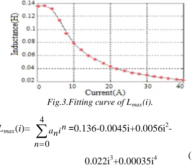
Lmax, Lmin can be obtained by experiments and electromagnetic field finite element analyzes (FEA). Lmax(i) can be expressed as a polynomial function with respect to the phase current which can be obtained by curve fitting Fig.3.
Fig.3.Fitting curve of Lmax(i).
Lmax(i)= in
n n a
∑
=
4
0
=
0.136-0.0045i+0.0056i2-0.022i3+0.00035i4
C. Torque Production
The variation of the reluctance between two extreme positions of aligned and unaligned positions will induce a variation of magnetic energy from which a non null average torque will result.
2
)
,
(
2
1
i
d
i
dL
T
e=
⋅
⋅
θ
θ
4. SRG POWER CONVERTER
Fig. 4 shows a conventional excitation circuit of SR generator using an asymmetry half bridge (1)
(2)
(7) (6)
(3)
(4)
[image:2.612.326.519.393.561.2]35 converter. In the figure, La, Lb, Lc, and Ld shows
the windings of the phase A, B, C and D, respectively. The resistor r is each winding resistance. The opposed two transistors turn on and turn off at the same time moment against the appropriate rotor position angle.
The stator pole is excited and it’s winding current increases when the transistors turn on. When the transistors turn off, the currents flow through the external load resistance RL and the
[image:3.612.92.284.243.340.2]generated electric power is supplied to the load resistance.
Fig.4. Circuit Configuration Of SR Generator Excited By AHBC
The circuit of AHBC is somewhat complicated because AHBC needs two transistors and two diodes per phase.
[image:3.612.334.516.311.507.2]In order to reduce the number of the devices, an SRC was proposed. Fig.5 illustrates a circuit configuration of the SRC.
Fig.5. Circuit Configuration Of SR Generator Excited
BySRC
(a) (b)
Fig. 6. Operation Modes Of SRC
(a) Exciting mode. (b) Generating mode.
Fig. 6 shows operation modes of SRC per phase.
When the transistor S is on, the DC voltage is supplied to winding and the current flows as shown by the solid loop in Fig. 6(a). When the transistor S is off, the current flows through the freewheeling diode and the external load resistance RL as shown in Fig. 6(b) b.
The SRC consists of half number of switching devices for AHBC. The same IGBT and power diode were used for both converters.
5. NONLINEAR SIMULATION MODEL OF SRG
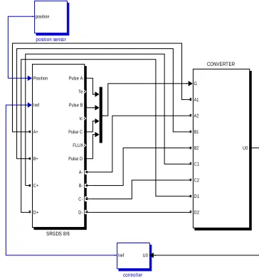
To test the proposed model feasibility a four phase 8/6 SRG system is built and simulated as shown in Fig.7. The rated parameters of the SRG are 3000 r.p.m 250 volt. The SRG was simulated under different conditions
Fig.7. Simulation Model of SRG System.
A. Model of Each Phase
We presents the model of windings, it is built according to (1)-(7). The parameters of each phase are symmetrical, take phase (a) example, its simulation model shows the detailed structure of the nonlinear machine modeling is created by Embedded Block in Fig. 6.
The three other phases are identical but different just on the level from the value of the angular shift where we take 0° for the phase (a), θs for the phase (b), 2θs for the phase (c), and
3θsfor the phase (d), θs is defined as:
1/Ns) -r (1/N 2
= Π
s
θ
U0 Iref
controller
Position
Iref Pulse A
Te Pulse B Ic Pulse C FLUX Pulse D A+
B+
C+
D+ A- B- C-
D-SRGDS 8/6
G
U0 A1
A2 B1 B2 C1 C2 D1 D2
CONVERTER position
position sensor
[image:3.612.93.287.426.688.2]ISSN: 1992-8645 www.jatit.org E-ISSN: 1817-3195
36
Fig.8.The Simulation Model Of Phase (A)
Signal to Source and Source to Signal are connecting elements between simulink modules and PSB modules. Signal to Source is a controlled current source, it converts current signal to a current source. Fig.9 shows the Inductance and current calculator of the winding.
Fig.9. Inductance And Current Calculator
Fig.10 shows the position sensor. The speed of the rotor is integrated to obtain the mechanical angle of the rotor.
Fig.10. The Simulation Model Of Position Sensor.
B. Design of the Controller
The objective of the controller system is to create a high performance control commands to maintain the output voltage of the system.
Fig.11. The Simulation Model Of Outer Voltage Controller.
6. NONLINEAR SIMULATION RESULTS
Fig.12 shows the nonlinear inductance phase and its variation when the rotor position changed.
Fig.12. Nonlinear inductance (H)
When speed is increased, the phase current is reduced and the generating capacity of SRG is degraded.
Fig.13. Phase Current Waveforms With Different Speeds
Fig.14 shows the output voltage response of SRG with no load.
Fig.14. Output Voltage (V) Vs Time (ms) Capacitor (across)The voltage will stabilize after a
shorttime. The ripples of the voltage are very small.
1
posi ti on
-C-ori gi nal angl e -C-Speed 1
s
1
Iref
270 given voltage signal
1
s Ki
Kp
1
Vout
0 10 20 30 40 50 60
0 0.02 0.04 0.06 0.08 0.1 0.12 0.14
Rotor Position(Degree)
Induc
tanc
e(
H
)
20 30 40 50 60 70 80
0 2 4 6 8 10 12 14 16 18 20
Rotor Position(Degree)
C
ur
rent
(A
m
ps
)
3500rpm 3000rpm 2500rpm
0 0.5 1 1.5 2 2.5 3
x 10-5
0 50 100 150 200 250 300
Time(s)
O
ut
put
V
ol
tage(
V
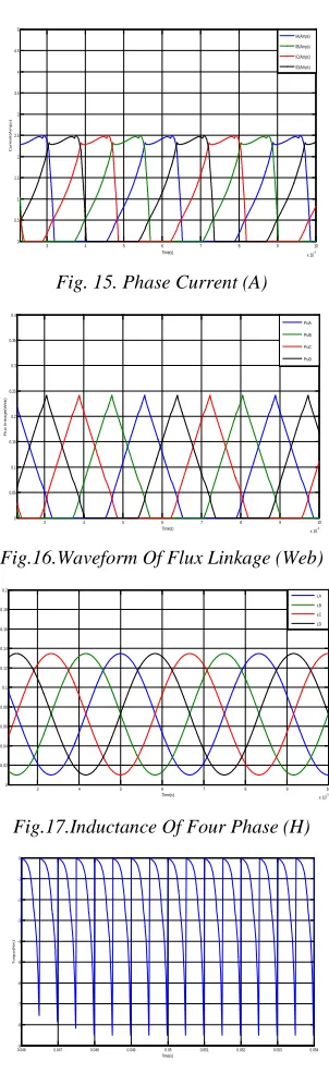
37 Fig.15 and Fig.16 presents the current and flux waveforms of four phases respectively.
Fig. 15. Phase Current (A)
Fig.16.Waveform Of Flux Linkage (Web)
[image:5.612.115.266.118.611.2]Fig.17.Inductance Of Four Phase (H)
Fig.18. Waveform Of The Torque (Nm)
7. CONCLUSION
The operating characteristics of the switched reluctance generator with SRC and AHBC were discussed and simulated under Matlab/Simulink environment. The results obtained with SRC are almost same as with AHBC. The SRC circuit has half of the power devices as AHBC and has
common ground of gate circuits for the power transistors. This means that the circuit configuration of the SRC is more simple, reliable, and low cost including the gate circuit. The 8/6 SR generator is expected that the application of the SR generator to a high-speed generator such as the microgas turbine. Furthermore, a multipolar SR generator is also interesting for the low-speed generator such as the wind turbine generator.
8.APPENDIX
Values of parameters used in modeling and simulation.
R=25Ω, Nr=4, Lmin=0.01H, Vexciting=250V,
RL=100Ω, θoriginal=10°, Kp=10, Ki=5.
REFERENCES
[1] G. Seguier, F. Notellet, “Electrotechnique Industrielle”, 2éme édition pages 371-384. [2] C.M. Stephens. IEEE Trans. IA,
27(6):1098-1102, 1991.
[3] Osamu Inhinokura, Tsukasa kikuchi, kanji nakammurg Tadaki Uatannable and Hai-jiau Guo,”Dynamic Simulation Model of Switched Reluctance Generator” IEEE Transactions vol. 39, no. 5, sep. 2003, pp. 3253-3255.
[4] M. K. EI-Nemr, M. A. Al-khazendar, E. M. Rashad and M. A. Hassanin “Modelling and steady state Analysis of Stand – Alone Switched Reluctance Generator “, IEEE Power Engineering Society General Meeting July 2003, pp. 1894-1899.
[5] F. Sores and P. J. Costa Branco,” Simulation of a 6/4 Switched Reluctance Model Based on MATLAB/Simulink Enviorment,” IEEE Transactions Aerospace and Electronics system, vol. 37, July 2005, pp. 989-1009. [6] Shoujun Son, Weiguo Liu, “A Novel
Method and Dynamic Simulation of a Four-Phase Switched Reluctance Generator System Based on Matlab/Simulink”, IEEE 2007.
3 4 5 6 7 8 9 10
x 10-3
0 0.5 1 1.5 2 2.5 3 3.5 4 4.5 5
Time(s)
C
ur
rent
(A
m
ps
)
IA(Amps) IB(Amps) IC(Amps) ID(Amps)
3 4 5 6 7 8 9 10
x 10-3
0 0.05 0.1 0.15 0.2 0.25 0.3 0.35 0.4
Time(s)
F
lux
link
age(
W
eb)
PsiA PsiB PsiC PsiD
3 4 5 6 7 8 9 10
x 10-3
0 0.02 0.04 0.06 0.08 0.1 0.12 0.14 0.16 0.18 0.2
Time(s)
Induc
tanc
e(
H
)
LA LB LC LD
0.046-9 0.047 0.048 0.049 0.05 0.051 0.052 0.053 0.054 -8
-7 -6 -5 -4 -3 -2 -1 0
Time(s)
T
or
que(
N
m