FREE VIBRATION CHARACTERISTICS ON A SPLIT
TORQUE TRANSMISSION
1ZHAOXIA HE, 2LEHAO CHANG, 2LAN LIU
1
Key Laboratory of Road Construction Technology and Equipment, Ministry of Education, Chang’an
University, Xi’an, 710064, China
2School of Mechanical Engineering, Northwestern Polytechnical University, Xi’an, 710072, China
E-mail: [email protected], [email protected]
ABSTRACT
The free vibration characteristics of a dual split torque transmission are studied in this work. A transverse-torsional coupling dynamic model is developed using lumped parameter method. The natural frequencies and mode shapes are calculated by solving the eigenvalue problem of the differential equations of motion. The vibration modes of the system are classified into translational mode and rotational mode, and the characteristics of the two modes are described in details. The modal strain energy and kinetic energy are introduced to study the impact of mesh stiffness, component masses and moments of inertia. The influence of the concerned parameter on a certain mode can be effectively determined by inspection of the modal energy distribution. The effect of the torsional stiffness of the shaft connecting two stages is also studied. The results presented in this work can provide references for the design of dynamic performance of the split torque transmission.
Keywords: Split Torque Transmission, Modal Analysis, Mesh Stiffness, Modal Strain Energy, Kinetic Energy
1. INTRODUCTION
The split torque transmission, also known as power split transmission or split path transmission, has been used in helicopter transmission since 1980s[1, 2]. It integrates the advantages of planet gear train and conventional parallel shaft gear trains. The system is symmetric in the overall, and for each path it is similar with the common gearing. The gears of each branch only transmit a part of the total torque compared to the simple parallel shaft gearing which must transmit the total torque. Therefore the trains have greater stiffness, better impact resistance and increased reliability than the parallel shaft gear train. This kind of transmission is also widely used in marine transmission to meet the demand of large load capacity and low noise.
Several scholars have performed much research to investigate the vibration and dynamic characteristics of the dual split torque transmission. M. Rashidi[3] built a linear dynamic model to search the effects of shaft location and mesh stiffness on the gear mesh forces of two power paths. T.L. Krantz[4] studied the effects of shaft angle, mesh phasing and compound shaft stiffness on the natural frequencies and dynamic response of the system. M. Rashidi and T.L. Krantz[5-7] had
also done a lot of research on the load sharing of the split torque transmission. A.V. Wolff[8] gained the bearing loads and load sharing characteristics for the system which had employed sliding bearings. Z. Yang[9] built a nonlinear torsional dynamic model and performed analysis about the influences of different design parameters.
In the present study, a transverse-torsional coupling dynamic model for a split torque gearbox is proposed. The free vibration characteristics of the system are investigated in the following analysis. Then the formulations to calculate the modal strain energy, support strain energy and kinetic energy for different vibration modes are derived. The effect of the torsional stiffness of connecting shaft is also studied in this paper.
2. DYNAMICMODELING
The system to be investigated is a dual split torque speed-increasing gear train used in a marine transmission. The schematic diagram of system is shown in Figure 1. The input gear g1 transfers the input torque to the two double helical gears g2 and
The lumped parameter model of the system is shown in Figure 2. As the symmetry of double helical gears, the axial vibration of all gears is ignored, only the transverse vibration in the horizontal and vertical directions is considered, as well as the vibration in rotation direction. The support and gear mesh are simplified as elastic element, while the gear body and connection are treated as rigid body. The deflections of all gears are described by translational coordinates xi, yi, and rotational coordinates ui (i= 1,…,6). The rotational coordinates ui=riθi, where θi is the component rotation; ri is the base circle radius for each gear. As all the bearings are sliding bearings, the details of bending stiffness are not given in Figure 2, which is only denoted by ki. According to the dynamic characteristics of oil film in sliding bearings, every
[image:2.612.318.521.204.342.2]ki includes four items, which are kixx, kixy, kiyx, kiyy respectively.
[image:2.612.108.273.326.483.2]Figure 1: Schematic Diagram Of The System
Figure 2: The Dynamic Model Of The System
When neglecting the friction on tooth surfaces, the generalized transverse-torsional coupling dynamic model for a double helical gear pair is illustrated in Figure 3. The subscript 1 is the driver
gear, and the subscript 2 is the driven gear. The relative gear mesh displacement can be denoted as:
b 2 2 2 1 i 1 i 1 12 cos ) cos sin cos sin ( b α α ϕ ϕ δ u y x u y x − − − + + = (1)
where βb is the base helix angle, α is the mesh angle, and φi=α-φi, in which φi is the fixed angle and is 0 and π respectively for the two paths.
ω2 x2 m2 R2 I2 O2 km1 ω1 y1 R1 O1 m1 I1
αφiφi
k2
y2
x1
k1
Figure 3: Generalized Model For The Gear Pair
Applying Newton’s second law, the undamped differential equations of motion of the input gear g1 can be derived as:
1 1 1 3 2 1 1 1 , 1 1 1 3 2 1 1 1 1 1 1 1 1 1 1 3 2 1 1 1 1 1 1 1 cos 0 cos cos 0 sin cos r T k u m k y k x k y m k y k x k x m b j j m eq b j j m yy yx b j j m xy xx = ⋅ + = ⋅ + + + = ⋅ + + +
∑
∑
∑
= = = b δ α b δ α b δ (2)where meq,1=I1/r1 is the equivalent mass in the rotation direction, I1 is the moment of inertia of g1,
T is the input torque. The equations of motion for the other gears can be obtained similarly. Assembling the equations in matrix form as:
F KX X
M+ =
(3)
where M represents the mass matrix, K is the stiffness matrix, F is exciting force vector, and X is the vector of the degrees of freedom of the system. Without considering the vibration of input shaft and output shaft, the system has a total of eighteen degrees of freedom for the six gears.
3. MODALANALYSIS
[image:2.612.96.297.516.650.2]j j
jMφ Kφ
λ =
(4)
where 2
j
j
ω
λ =
, ωj is the j-th natural frequency, [image:3.612.87.302.164.413.2]φj is the corresponding mode shape.
Table 1: Parameters Of The System
Gear g1 g2, g3 g4, g5 g6
Teeth Number 79 44 125 31
Module(mm) 2.25 2.25 1.75 1.75
Face Width(mm) 60 60 40 40
Mass(kg) 36.20 18.31 33.33 4.53
Moment of Inertia
(103×kg∙mm2) 139.58 29.4 214.1 1.41 Base Radius(mm) 89.62 49.91 111.6 27.68
Mesh Angle(°) α1=21.53; α2=21.80
Base Helix Angle(°) βb1=21.27; βb2=22.93
Mesh Stiffness
(kN/μm) km1=1.82; km2=1.25 Bearing
Stifness(kN/μm) kkixxiyy=6, =4 kixy=1, kiyx=0.8, Torsional
Stiffness(N∙m/rad) kt=1×10⁷
3.1 Natural Frequencies And Vibration Modes
[image:3.612.316.520.348.559.2]The natural frequencies of the system are different from each other, and all the mode shapes can be classified into two types: translational mode (TM) and rotational modes (RM). Table 2 outlines the natural frequencies and the corresponding vibration modes. The system is positive semidefinite and therefore has a rigid body mode, with the frequency 0Hz. There are ten translational modes and seven rotational modes for the investigated model.
Table 2: Natural Frequencies And Mode Types
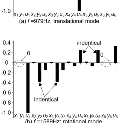
The normalized modal deflections for the two vibration modes are shown in Figure 4. For translational modes, the two center gears (g1, g6) have pure translational movements, and the rotational deflections are zero. The two branch gears of each stage have opposite deflections in this mode, see Figure 4(a). For rotational modes, the two center gears have pure rotational movements, and the translational deflections are zero. The two branch gears of each stage have identical deflections in this mode, see Figure 4(b).
Figure4: The dynamic model of the system
3.2 Sensitivity Of Natural Frequencies To Mesh Stiffness
It was found by J. Lin and R. G. Parker that the natural frequency sensitivity to certain stiffness is uniquely associated with the modal strain energy stored in that spring [10]. The mesh strain energy is generated due to gear distortion, and for the first stage it is defined as:
∑
=
= 3
2
2 1 1
1 ( )
2 1
i
i m
m k
U δ (5)
NO. f (Hz) Mode
type NO. f (Hz)
Mode type
1 0 - 10 2449 RM
2 979 TM 11 2487 TM
3 1589 RM 12 3001 RM
4 1655 RM 13 3010 TM
5 1728 TM 14 4000 TM
6 1779 TM 15 4115 RM
7 2163 TM 16 5673 TM
8 2181 RM 17 5855 RM
where Um1 is the mesh strain energy of first stage, km1 is the mean mesh stiffness,
δ
1j is the relative deflection as expressed in Equation (1).The derivative of eigenvalue with respect to mesh stiffness km1 is expressed as:
1 1 3
2 2 1 1
2 ) (
m m
i i m
j
k U
k = =
∂ ∂
∑
= δ
λ (6)
[image:4.612.93.280.329.463.2]Therefore, the mesh strain energy can intuitively reflect the effects of mesh stiffness on the concerned natural frequency. The mesh strain energy of the second stage can be obtained similarly. Figure 5 shows the mesh strain energy for all natural frequencies. As the modal deflection has been normalized, the mesh strain energy calculated here is also dimensionless. The x-axis is the number of every frequency, and y-axis is the relative value of mesh strain energy.
Figure 5: Mesh Strain Energy For All Mode Shapes
It can be obviously seen from Figure 5 that the mesh stiffness of first stage has greater impact on the third, fourth, fifth, seventh, tenth, eleventh, twelfth, thirteenth, fourteenth and fifteenth frequencies than the mesh stiffness of second stage, and the reverse effects are appeared for the other frequencies. The results are consistent with the modal deflections for 979Hz (mode 2) and 1589Hz (mode 3) as depicted in Figure 4. For mode 2, deflections of the second stage is greater than the first stage, so more strain energy is stored in Um2 than in Um1. Consequently, ω2 is more sensitive to
km2 than to km1. In the same way, it can be found that ω3 is more sensitive to km1 than to km2.
3.3 Sensitivity Of Natural Frequencies To Bearing Stiffness
Similar to the mesh strain energy, the support strain energies for bearing stiffnesses are defined as:
) (
2 1
2 2 2 2
i yy i xy i yx i xx
iyy ixy iyx ixx i
y k y k x k x k
U U U U U
+ + + =
+ + + =
(7)
Where Ui, i = 1,…6 is the total support strain energies in the bearing of gear i, Uixx, Uiyx, Uixy,
Uiyy are the strain energies in the four support
springs of sliding bearing, respectively.
The derivative of eigenvalue with respect to bearing stiffness is:
) (
4 ) (
2 2 2
iyy ixy
iyy ixy
iyx ixx
iyx ixx i
i i
j
k k
U U k k
U U y
x
k +
+ + + + =
+ = ∂
∂
λ
(8)Figure 6 shows the distribution of strain energies for all bearings in 979Hz and 1589Hz. As the description in Figure 4, the branch gears have the opposite or the identical modal deflections for the two mode types, so the strain energies of the branch gears are equal. The natural frequency ω2 (979Hz) is most sensitive to the bearing stiffness of g6, and
[image:4.612.341.500.419.616.2]ω3 (1589Hz) is most sensitive to the bearing stiffness of g2, g3. It can be also seen that the rotational mode (1589Hz) is independent of the bearing stiffness of the center gears g1 and g6 because there are no modal deflections for them in this mode.
Figure 6: Support strain energy of all bearings
3.4 Sensitivity Of Natural Frequencies To Mass Property
The modal kinetic energy of the system is defined as:
)
(
2
1
2 2 2i i i j
i
m
x
y
2 , 2 ,
2
1
i i eq j u
i
m
u
T
=
ω
(10) [image:5.612.92.297.176.507.2]where Ti (i=1,2,…,6)is the translational kinetic energy of different gears, Ti,u (i=1,2,…,6) is the kinetic energy associated with a certain moment of inertia.
Figure 7: Distribution Of Kinetic Energies
The derivative of eigenvalue with respect to mass is expressed as:
i i i
i j i j
m T y
x m
2 ) ( 2+ 2 =−
− = ∂ ∂
λ
λ (11)
i eq
u i i
i i eq
j
m T u
m ,
, 2
,
2
− = − = ∂
∂
λ
λ
(12)
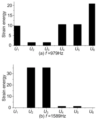
Therefore, the kinetic energies can be used to estimate the impact of mass properties on different frequencies. Figure 7 shows the distribution of kinetic energies in 979Hz and 1589Hz. As can be seen in Figure 7(a), the moments of inertia of g4, g5 have significant effect on the natural frequency 979Hz. We can conclude that the rotational deflections of g4 and g5 may be the principal deflections in 979Hz. After observing the mode
shapes of 979Hz, the conclusion agrees well with the description in Figure 4(a). The masses of g1, g4,
g5 and the moments of inertia of g2, g3 have comparatively small effect; while the others have little effect on the mode shape in 979Hz. Besides, for T1u and T6u are equal to zero, the mode shape in 979Hz is independent of the inertias of the center gears. Figure 7(b) indicates that the moment of inertia of g1 is the main factor that affects the mode shape of 1589Hz, and the masses of center gears have no effects on this mode shape.
3.5 Effect of Connecting Shaft
The natural frequencies are calculated as the torsional stiffness of connecting shaft kt is varied from 1×10⁷ N/m to 3×10⁷ N/m. It can be seen from Figure 8 that with the variation of shaft stiffness, most of the natural frequencies do not change except mode 14 and mode 15. The natural frequencies of mode 14 and mode 15 will increase linearly with the increase of shaft stiffness. It’s observed from Figure 9 that the modal deflections of g2 and g3 are the major components of the mode shapes for mode 14 and mode 15. Therefore, the shaft stiffness mainly affects the vibration of adjacent pinions but not the large gear.
1000 2000 3000 4000 5000 6000 7000
1.0×10⁷ 1.5×10⁷ 2.0×10⁷ 2.5×10⁷ 3.0×10⁷
Natural frequency
(Hz
)
Mode 14 Mode 15
8000
kt (N/m)
Figure 8: Natural Frequencies Versus The Shaft Stiffness
-1.0 -0.5 0.0 0.5 1.0
-1.0 -0.5 0.0 0.5 1.0
x1y1u1x2y2u2x3y3u3x4y4u4x5y5u5x6y6u6
x1y1u1x2y2u2x3y3u3x4y4u4x5y5u5x6y6u6
Mode 14
Mode 15
Figure 9: Mode Shapes When Kt Equals To 1×10⁷
[image:5.612.318.516.399.538.2]4. CONCLUSION
A dynamic model of a split torque transmission has been developed in order to investigate the free vibration characteristics of the system. The influence of several key design parameters have been studied in this paper. There are two vibration modes for the split torque transmission: translational mode and rotational mode. The simplified formulae for mesh strain energy, support strain energy can directly reflect the influences of mesh stiffness and bearing stiffness on a certain vibration mode. The bearing stiffness has no effect on the center gears in rotational mode. The mode shape in rotational mode is independent of the masses of the center gears, while the translational mode is independent of the moments of inertias of the center gears. The variation of the torsional stiffness of the connecting shaft mainly has impact on its adjacent pinions and the corresponding natural frequencies. Future work will aim at the dynamic response and load sharing analysis of the split torque system.
ACKNOWLEDGEMENT
This work is supported by the National Natural Science Foundation of China (51205029) and the Special Fund for Basic Scientific Research of Central Colleges, Chang’an University (CHD2011JC177).
REFRENCES:
[1] G. White, “Split-Torque Helicopter Transmission with Widely Separated Engines”, Proceedings of the Institution of Mechanical Engineers, Part G: Journal Aerospace Engineering, Vol. 203, No.G1, 1989, pp.53-65.
[2] Jules G. Kish, “Sikorsky Aircraft Advanced Rotorcraft Transmission”, NASA Contractor Report 191079, 1993.
[3] M. Rashidi, T. L. Krantz, “Dynamics of a Split Torque Helicopter Transmission”, NASA Technical Memorandum 105681, 1992.
[4] T. L. Krantz, M. Rashidi, “Vibration Analysis of a Split Path Gearbox”, NASA Technical Memorandum 106875, 1996. [5] T. L. Kranz, M. Rashidi and J.G.. Kish,
“Split Torque Transmission Load Sharing”, NASA Technical Memorandum 105884, 1992.
[6] T. L. Krantz, “A Method to Analyze and Optimize the Load Sharing of Split Path
Transmissions”, NASA Technical
Memorandum 107201, 1996.
[7] T. L. Krantz, I. R. Delgado, “Experimental Study of Split-Path Transmission Load Sharing”, NASA Technical Memorandum 107202, 1996.
[8] A. V. Wolff, “Analysis of a Split-Path Gear Train with Fluid-Film Bearings”, Virginia Polytechnic Institute and State University, Master Thesis, 2004.
[9] Z. Yang, S. M. Wang and Y.S. Fan, “Nonlinear Dynamics Characteristics of Split-torque Gear Transmission System”,
Chinese Journal of Mechanical Engineering, Vol.44, No.7, 2008, pp.52-57.
[10] J. Lin, R. G. Parker, “Sensitivity of Planetary Gear Natural Frequencies and Vibration Modes to Model Parameters”,