CP /
M-68J(TM
Operating System
CP/M-68KTM
Operating System
System Guide
Copyr ight
©
1983Digital Research
P.O. Box 579
167 Central Avenue Pacific Grove, CA 93950
(408) 649-3896 TWX 910 360 5001
COPYRIGHT
Copyright
©
1983 by Digital Research. All rightsreserved. No part of this publication may be
reproduced, transmitted, transcribed, stored in a retrieval system, or translated into any language or computer language, in any form or by any means, electron ic, mechan ical, magnetic, optical, chemical, manual or otherwise, without the prior written permission of Dig ital Research, Post Office Box 579, Pacific Grove, California, 93950.
DISCLAIMER
Digital Research makes no representations or warranties with respect to the contents hereof and spec ifically disclaims any implied warranties of merchantability or fitness for any particular
purpose. Further, Digital Research reserves the
right to rev ise this publica tion and to make changes from time to time in the content hereof without obligation of Digital Research to notify any person of such revision or changes.
TRADEMARKS
CP/M and CP/M- 86 are reg is te red trademarks of
Digital Research. CP/M-80, CP/M~68K, DDT, and MP/M
are trademarks of Digital Research. Motorola
MC68000 is a registered trademark of Motorola,
Incorporated. EXORmacs, EXORterm, and MACSbug are
trademarks of Motorola, Inc. VAX/VMS is a trademark
of Digital Equipment Corporation. UNIX is a
trademark of Bell Laboratories. TI Silent 700
Te r min a 1 is a reg is te red tradema rk of Texas
Instruments, Incorporated.
The CP/M-68K Operating System System Guide was prepared using the Digital Research TEX Text Formatter and printed in the United States of America.
************************************
*
First Edition: January 1983*
Foreword
CP/M-68K™ is a single-user general purpose operating system. It is designed for use with any disk-based computer using a Motorola® MC68000 or compatible processor. CP/M-68K is modular in design, and can be modified to suit the needs of a particular installation.
The hardware interface for a particular hardware environment is
supported by the OEM or CP/M-68K distributor. Digital Research
supports the user interface to 68K as documented in the
CP/M-68K Operating System User's Guide. Digital Research does not
support any additions or modifications made to CP/M-68K by the OEM or distr ibu ter.
Purpose and Audience
This manual is intended to provide the information needed by a systems programmer in adapting CP/M-68K to a particular hardware
env ir onmen t. A substantial degree of programming expertise is
assumed on the part of the reader, and it is not expected that typical users of CP/M-68K will need or want to read this manual.
Prerequisites and Related Publications
In addition to this manual, the reader should be familiar with the architecture of the Motorola MC68000 as described in the Motorola l6-Bit Microprocessor User's Manual (third edition), the CP/M-68K User's and Programmer's Gu ides, and, of course, the deta ils of the hardware environment where CP/M-68K is to be implemented.
Bow This Book is Organized
Section 1 presents an overview of CP/M-68K and describes its
major components. Section 2 discusses the adaptation of CP/M-68K
for your specific hardware system. Section 3 discusses bootstrap
procedures and related information. Section 4 describes each BIOS
function including entry parameters and return values. Section 5
de sc r ibes the process of creating a BIOS for a custom hardware
interface. Section 6 discusses how to get CP/M® working for the
first time on a new hardware environment. Section 7 describes a
procedure for causing a command to be automatically executed on cold
boot. Section 8 describes the PUTBOOT utility, which is useful in
generating a bootable disk.
Appendix A descr ibes the conten ts of the CP/M-68K distr ibu tion
disks. Appendixes B, C, and D are listings of various BIOSes.
Appendix E contains a listing of the PUTBOOT utility program. Appendix F describes the Motorola S-record representation for programs.
Table of Contents
1 System Overview
1.1 Introduction
1.2 CP/M-68K Organization • • •
1.3 Memory Layout •
1.4 Console Command Processor
1.5 Basic Disk Operating System (BDOS)
1.6 Basic I/O System (BIOS)
1.7 I/O Devices • . . • • • •
1.7.1 Character Devices 1.7.2 Character Devices
1.8 System Generation and Cold Start Operation
2 System Generation
2.1 Overview
2.2 Creating CPM.SYS
2.3 Relocating utilities
3 Bootstrap Procedures
3.1 Bootstrapping Overview
3.2 Creating the Cold Boot Loader • .
3.2.1 Writing a Loader BIOS 3.2.2 Building CPMLDR.SYS
4
BIOS Functions4.1 Introduction
v
1
3
3
4
5
5
5
5
5
6
7
7
8
9
10
10 11
Table of Contents
( continued)
5 Creating a BIOS
5.1 Overview
5.2 Disk Definition Tables
5.2.1 5.2.2 5.2.3
Disk Parameter Header Sector Translate Table • Disk Parameter Block
5.3 Disk Blocking Guide . • • •
5.3.1 5.3.2 5.3.3 5.3.4 5.3.5
A Simple Approach Some Refinements • • Track Buffering LRU Replacemen t
The New Block Flag • •
6 Insta11ing and Adapting the Distributed BIOS and CP/M-68K
6.1 Overview
6.2 Booting on an EXORmacs
6.3 Bringing up CP/M-68K Using S-record Files.
7 Co1d Boot Automatic Command Execution
7.1 Overview
39
39
40 41
42
45
46 46
47 47 48
49
49
50
51
7.2 Setting up Cold Boot Automatic Command Execution 51
8 The POTBOOT Oti1ity
8.1 PUTBOOT Operation.
8.2 Invoking PUT BOOT
vi
53
Appendixes
A Contents of Distribution Disks • • • • •
B Sample BIOS Written in Assembly Language
C Sample Loader BIOS Written in Assembly Language
D EXORrnac s BIOS Wr it ten in C • • • • • • •
E PUTBOOT Utility Assembly Language Source
F The Motorola S-record Format .
F.l S-record Format
F.2 S-record Types
G CP/M-68K Error Messages
vii
55
59
67
73
101
• • 107
107
• • 108
Tables and Figures
Tab1es
1-1. CP/M-68K Terms • • .
4-l. 4-2. 4-3. 4-4.
5-l. 5-2. 5-3. 5-4.
A-l.
BIOS Register Usage
BIOS Functions • • . • • • • • . . • • • • • CP/M-68K Logical Device Characteristics
I/O Byte Field Definitions • . • . . • • •
Disk Parameter Header Elements
Disk Parameter Block Fields . . • • • . • • • • . BSH and BLM Va lues • • . . • . . • . . • • • • • . EXM Values . . . • • • . • • • • . . • • • •
Distribution Disk Contents.
1
14 14 33 34
40 42 44 45
55
F-l. S-Record Field Contents F-2. S-Record Types . • • • •
• • • • • • • • • • 107 • • • • • • • 109
G-l. CP/M-68K Error Messages
Figures
1-1. CP/M-68K Interfaces • • . • . • • • • 1-2. Typical CP/M-68K Memory Layout •
4-1. Memory Region Table Format • 4-2. I/O Byte Fields • • • • •
5-l. 5-2. 5-3.
Disk Parameter Header • . • . Sample Sector Translate Table Disk Parameter Block • • • • •
F-l. S-Reference Fields • • • • • . •
viii
• • • 109
3 4
32
34
40 42 42
1.1 Introduction
Section 1
System Overview
CP/M-68K is a single-user, general purpose operating system for microcomputers based on the Motorola MC68000 or equivalent
microprocessor chip. It is designed to be adaptable to almost any
hardware environment, and can be readily customized for particular hardware systems.
CP/M-68K is equivalent to other CP/M systems with changes
dictated by the 68000 architecture. In particular, CP/M-68K
supports the very large address space of the 68000 family. The
CP/M-68K file system is upwardly compatible with CP/M-80lM version
2.2 and CP/M-86@ Version 1.1. The CP/M-68K file structure allows
files of up to 32 megabytes per file. CP/M-68K supports from one
to sixteen disk drives with as many as 512 megabytes per drive.
The entire CP/M-68K operating system resides in memory at all
times, and is not reloaded at a warm start. CP/M-68K can be
configured to reside in any portion of memory above the 68000
exception vector area (OH to 3FFH). The remainder of the address
space is available for applications programs, and is called the transient program area, TPA.
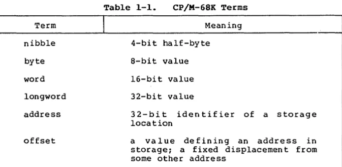
Several terms used throughout this manual are defined in Table 1-1.
Term
nibble
byte
word
longword
address
offset
Table 1-1. CP/M-68K Terms
J
Meaning4-bi t half-byte
8-bit value
16-bit value
32-bit value
32-bit identifier of a storage location
a value defining an address in
storage; a fixed displacemen t from some other address
[image:10.470.75.423.326.496.2]CP/M-68K System Guide 1.1 Introduction
Table 1-1. (continued)
Term
text segment
data segment
block storage segment (bss)
absolute
relocatable
I
Meaningprogram section containing machine instructions
program section containing initialized data
program section containing uninitialized data
describes a program which must reside at a fixed memory address.
descr ibes a program wh ich includes relocation information so it can be loaded into memory at any address
The CP/M-68K programming model is described in detail in the
CP/M-68K Operating System Programmer's Guide. To summarize that
model briefly, CP/M-68K supports four segments within a program: text, data, block storage segment (bss), and stack. When a program is loaded, CP/M-68K allocates space for all four segments in the TPA, and loads the text and data segments. A transient program may manage free memory using values stored by CP/M-68K in its base page.
[image:11.469.53.400.45.328.2]CP/M-68K System Guide
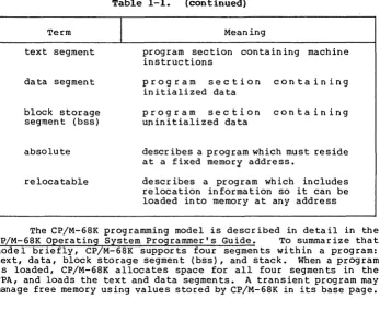
User Interface
(CCP)
programming Interface
(BOOS)
Hardware Interface
(BIOS)
HARDWARE ENVIRONMENT
[image:12.470.170.303.41.365.2]1.1 Introduction
Figure 1-1. CP/M-68K Interfaces
1.2 CP/M-68K Organization
CP/M-68K comprises three system modules: the Console Command Processor (CCP) the Basic Disk Operating System (BOOS) and the Basic
Input/Output System (BIOS). These modules are linked together to
form the operating system. They are discussed individually in this section.
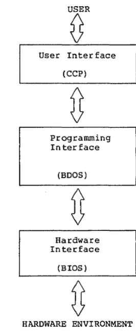
1.3 Memory Layout
The CP/M-68K operating system can reside anywhere in memory
except in the interrupt'vector area (OH to 3FFH). The location of
CP/M-68K is defined dur ing system genera tion. Usually I the CP/M-68K
opera ting system is placed at the top end (high address) of available memory,' and the TPA runs from 400H to the base of the
CP/M-68K System Guide 1.3 Memory Layout
operating system. It is possible, however, to have other
organizations for memory. For example, CP/M-68K could go in the low part of memory with the TPA above it. CP/M-68K could even be placed in the middle of available memory.
However, because the TPA must be one contiguous piece, part of memory would be unavailable for transient programs in this case. Usually this is wasteful, but such an organization might be useful ifan area of memory is to be used for a bit-mapped graphics device,
for example, or if there are ROM-resident routines. The BIOS and
specialized application programs might know this memory exists, but it is not part of the TPA.
CCP & BOOS & BIOS
User Stack
Free Memory
bss
Data
Text
Base Page
Interrupt Vectors
Top
of-Memory
I
I
CP/M 68K
TPA
OOSOOH
00400H
OOOOOH
user pgm
Figure 1-2. Typical CP/M-68K Memory Layout
1.4 Console Command Processor (CCP)
The Console Command Processor, (CCP) provides the user
interface to CP/M-68K. It uses the BDOS to read user commands and
load programs, and provides several built-in user commands. It also provides parsing of command lines entered at the console.
[image:13.470.99.330.173.415.2]CP/M-68K System Guide 1.5 Basic Disk Operating System
1.5 Basic Disk Operating System (BDOS)
The Basic Disk Operating System (BOOS) provides operating
system services to applications programs and to the CCP. These
include character I/O, disk file I/O (the BOOS disk I/O operations comprise the CP/M-68K file system), program loading, and others.
1.6 Basic I/O System (BIOS)
The Basic Input Output System (BIOS) is the interface between
CP/M-68K and its hardware environment. All physical input and
output is done by the BIOS. It includes all physical device
drivers, tables defining disk characteristics, and other hardware
specific functions and tables. The CCP and BOOS do not change for
different hardware environments because all hardware dependencies
have been concentrated in the BIOS. Each hardware configuration
needs its own BIOS. Section 4 describes the BIOS functions in
detail. Section 5 discusses how to write a custom BIOS. Sample
BIOSes are presented in the appendixes.
1.1 I/O Devices
CP/M-68K recognizes two basic types of I/O devices: character devices and disk drives. Character devices are serial devices that
handle one character at a time. Disk devices handle data in units
of 128 bytes, called sectors, and provide a large number of sectors
which can be accessed in random, nonsequential, order. In fact,
real systems might have devices with characteristics different from
these. I t is the BIOS IS responsibility to resolve differences
between the logical device models and the actual physical devices.
1.7.1 Character Devices
Character devices are input output devices which accept or
supply streams of ASCII characters to the computer. Typical
character devices are consoles, printers, and modems. In CP/M-68K
operations on character devices are done one character at a time. A character input device sends ASCII CTRL-Z (lAB) to indicate end-of-file.
1.1.2 Character Devices
Disk devices are used for file storage. They are organized
into sectors and tracks. Each sector contains 128 bytes of data.
(If sector sizes other than 128 bytes are used on the actual disk, then the BIOS must do a logical-to-physical mapping to simulate 128-byte sectors to the rest of the system.) All disk I/O in CP/M-68K is
done in one-sector units. A track is a group of sectors. The
number of sectors on a track is a constant depending on the
particular device. (The characteristics of a disk device are
specified in the Disk Parameter Block for that device. See
CP/M-68K System Guide 1.7 I/O Devices
Section 5.) To locate a particular sector, the disk, track number, and sector number must all be specified.
1.8 System Generation and Cold Start Operation
Generating a CP/M-68K system is done by linking together the CCP, BOOS, and BIOS to create a file called CPM.SYS, which is the
operating system. Section 2 discusses how to create CPM.SYS.
CPM.SYS is brought into memory by a bootstrap loader which will
typically reside on the first two tracks of a system disk. (The
term system disk as used here simply means a disk with the file CPM.SYS and a bootstrap loader.) Creation of a bootstrap loader is
discussed in Section
s.
End of Section I
2.1 Overview
Section 2
System Generation
This section describes how to build a custom version of CP/M-68K by combining your BIOS with the CCP and BOOS supplied by Digital Research to obtain a CP/M-68K operating system suitable for your spec if ic hardware system. Sec tion 5 descr ibes how to create a BIOS.
In this section, we assume that you have access to an already
configured and executable CP/M-68K system. If you do not, you
should first read Section 6, which discusses how you can make your first CP/M-68K system work.
A CP/M-68K opera ting system is genera ted by using the linker, L068, to link together the system modules (CCP, BOOS, and BIOS). Then the RELOC utility is used to bind the system to an absolute
memory location. The resulting file is the configured operating
system. It is named CPM.SYS.
2.2 Creating CPM.SYS
The CCP and BOOS for CP/M-68K are distributed in a library
file named CPMLIB. You must link your BIOS with CPMLIB using the
following command:
A>L068 -R -UCPM -0 CPM.REL CPMLIB BIOS.O
where BIOS.O is the compiled or assembled BIOS. This c rea tes
CPM.REL, which is a relocatable version of your system. The cold
boot loader, however, can load only an absolute version of the system, so you must now create CPM.SYS, an absolute version of your
system. If you want your system to reside at the top of memory,
first find the size of the system with the following command:
A>SIZE68 CPM.REL
This gives you the total size of the system in both decimal
and hex byte counts. Subtract this number from the highest memory
address in your system and add one to get the highest possible address at which CPM.REL can be relocated. Assuming that the result is aaaaaa, type this command:
A>RELOC -Baaaaaa CPM.REL CPM.SYS
The result is the CPM.SYS file, relocated to load at memory
address aaaaaa. If you want CPM.SYS to reside at some other memory
address, such as immediately above the exception vector area, you can use RELOC to place the system at that address.
CP/M-68K System Guide 2.2 Creating CPM.SYS
When you perform the relocation, verify that the resulting
system does not overlap the TPA as defined in the BIOS. The
boundaries of the system are determined by taking the relocation address of CPM.SYS as the base, and adding the size of the system (use SIZE68 on CPM.SYS) to get the upper bound. This address range must not overlap the TPA that the BIOS defines in the Memory Reg ion Table.
2.3 Relocating utilities
Once yo~ have built CPM.SYS, it is advisable to relocate the
operating system utilities for your ",TPA using the RELOC utility. RELOC is described in the CP/M-68K Operating System Programmer's
Guide. This results in the utilities being absolute, rather than
relocatable, but they will occupy half the disk space and load into
memory twice as fast in their new form. You should also keep the
relocatable versions backed up in case you ever need to use them in a different TPA.
End of Section 2
Section 3
Bootstrap Procedures
3.1 Bootstrapping Overview
Bootstrap loading is the process of br ing ing the CP/M-68K operating system into memory and passing control to it. Bootstrap loading is necessarily hardware dependent, and it is not possible to discuss all poss ible var ia tions in th is manual. However, the manual pre sen ts a model of bootst.rapping that is applicable to most systems.
The model of bootstrapping which we present assumes that the CP/M-68K operating system is to be loaded into memory from a disk in which the first few tracks (typically the first two) are reserved for the opera ting system and bootstrap rou tines, wh ile the rema inder of the disk contains the file structure, consisting of a directory
and disk files. (The topic of disk organization ana parameters is
disc ussed in Sec tion 5.) In our model, the CP/M-68K operating
system resides in a disk file named CPM.SYS (described in Section 2), and the system tracks contain a bootstrap loader program
(CPMLDR.SYS) which knows how to read CPM.SYS into memory and
transfer control to it.
Most systems have a boot procedure similar to the following:
1) When you press reset, or execute a boot command from a
monitor ROM, the hardware loads one or more sectors
beginning at track 0, sector 1, into memory at a predetermined address, and then jumps to that address.
2) The code that came from track 0, sector 1, and is now executing, is typically a small bootstrap rou tine that loads the re st of the sec tor s on the system tracks (containing CPMLDR) into another predetermined address in
memory, and then jumps to that address. Note that if your
hardware is smart enough, steps 1 and 2 can be combined into one step.
3) The code loaded in step 2, which is now executing, is the CP/M Cold Boot Loader, CPMLDR, which is an abbreviated
version of CP/M-68K itself. CPMLDR now finds the file
CPM.SYS, loads it, and jumps to it. A copy of CPM.SYS is
now in memory, executing. This completes the bootstrapping process.
In order to create a CP/M-68K diskette that can be booted, you
need to know how to create CPM.SYS (see Section 2.2), how to create
the Cold Boot Loader, CPMLDR, and how to put CPMLDR onto your system tracks. You must also understand your hardware enough to be able to design a method for bringing CPMLDR into memory and executing it.
CP!M-68K System Guide 3.2 Creating the Cold Boot Loader
3.2 Creating the Cold Boot Loader
CPMLDR is a min iature version of CP!M-68K. It contains
stripped versions of the BOOS and BIOS, with only those functions which are needed to open the CPM.SYS file and read it into memory. CPMLDR will exist in at least two forms; one form is the information
in the system tracks, the other is a file named CPMLDR.SYS which is
created by the linker. The term CPMLDR is used to refer to either
of these forms, but CPMLDR.SYS only refers to the file.
CPMLDR.SYS is generated using a procedure similar to that used
in generating CPM.SYS. That is, a loader BIOS is linked with a
loader system library, named LDRLIB, to produce CPMLDR.SYS.
Additional modules may be linked in as required by your hardware. The resulting file is then loaded onto the system tracks using a utility program named PUTBOOT.
3.2.1 Writing a Loader BIOS
The loader BIOS is very similar to your ordinary BIOS; it just has fewer functions, and the en try conven tion is slightly differen t. The differences are itemized below.
1) On ly one disk needs to be suppor ted. The loader system
selects only drive A. If you want to boot from a drive
other than A, your loader BIOS should be written to select
that other drive when it receives a request to select drive A.
2) The loader BIOS is not called through a trap; the loader
BDOS calls an en try poin t named bios instead. The
parameters are still passed in reg isters, just as in the
normal BIOS. Thus, your Function 0 does not need to
initialize a trap, the code that in a normal BIOS would be
the Trap 3 handler should have the label bios, and you
exit from your loader BIOS with an RTS instruction instead of an RTE.
3) Only the following BIOS functions need to be implemented:
O· (Init) Called just once, should initialize hardware
as necessary, no return value necessary. Note that
Func tion 0 is called via bios with the function number
equal to O. You do not need a separate _init entry point.
4 (Conout) Used to print error messages during boot. If
you do not wan terror mes.sages, this function should just be an rts.
9 (Seldsk) Called just once, to select drive A.
10 (Settrk)
CP/M-6SK System Guide
11 (Setsec)
12 (Setdma)
13 (Read)
16 (Sectran)
3.2 Creating the Cold Boot Loader
IS (Get MRT) Not used now, but may be used in future
releases.
22 (Set exception)
4) You do not need to include an allocation vector or a check vector, and the Disk Parameter Header values that point to
these can be anything. However, you still need a Disk
Parameter Header, Disk Parameter Block, and directory buffer.
It is possible to use the same source code for both your normal BIOS and your loader BIOS if you use cond itional compila tion or
assembly to distinguish the two. We have done this in our example
BIOS for the EXORmacs!"
3.2.2 Building CPMLDR.SYS
Once you have written and compiled (or assembled) a loader BIOS, you can build CPMLDR.SYS in a manner very similar to building
CPM.SYS. There is one additional complication here: the result of
this step is placed on the system tracks. So, if you need a small
prebooter to bring in the bulk of CPMLDR, the prebooter must also be
included in the link you are about to do. The details of what must
be done are hardware dependent, but the following example should help to clarify the concepts involved.
Suppose that your hardware reads track 0, sector 1, into memory
at location 400H when reset is pressed, then jump to 400H. Then
your boot disk must have a small program in that sector that can load the rest of the system tracks in to memory and execute the code
that they contain. Suppose that you have written such a program,
assembled it, and the assembler output is in BOOT.O. Also assume
that your loader BIOS object code is in the file LDRBIOS.O. Then
the following command links together the code that must go on the system tracks.
A>lo68 -s -T400 -uldr - 0 cpmldr.sys boot.o ldrlib ldrbios.o
Once you have created CPMLDR.SYS in this way, you can use the
PUTBOOT utility to place it on the system tracks. PUTBOOT is
described in Section S. The command to place CPMLDR on the system tracks of drive A is:
A>putboot cpmldr.sys a
CP/M-68K System Guide 3.2 Creating the Cold Boot Loader
PUTBOOT reads the file CPMLDR.SYS, strips off the 28-byte command file header, and puts the result on the specified drive. You can now boot from this disk, assuming that CPM.SYS is on the disk.
End of Sec tion 3
4.1 Introduction
Section 4
BIOS Functions
All CP/M-68K hardware dependencies are concentrated in subroutines that are collectively referred to as the Basic I/O System (BIOS). A CP/M-68K system implemen tor can ta ilor CP/M-68K to fit nearly any 68000 operating environment. This section describes
each BIOS function: its calling conventions, parameters, and the
actions it must perform. The discussion of Disk Definition Tables
is treated separa tely in Sec tion 5.
When the BOOS calls a BIOS function, it places the function number in register DO.W, and function parameters in registers 01 and
02. It then executes a TRAP 3 instruction. DO.W is always needed
to specify the function, but each function has its own requirements for other para·meters, which are descr ibed in the sec tion descr ibing
the particular function. The BIOS returns results, if any, in
reg ister DO. The size of the result depends on the particular
function.
Note: the BIOS does not need to preserve the contents of registers. That is, any register contents which were valid on entry to the BIOS
may be destroyed by the BIOS on exit. The BOOS does not depend on
the BIOS to preserve the contents of data or address registers. Of course, if the BIOS uses interrupts to service I/O, the interrupt handlers will need to preserve registers.
Usually, user applications do not need to make direct use of
BIOS functions. However, when access to the BIOS is required by
user software, it should use the BnOS Direct BIOS Function, Call 50,
instead of calling the BtOS with a TRAP 3 instruction. This rule
ensures that applications remain compatible with future systems.
The Disk Parame ter Header (DPH) and Disk Parame ter Block (DPB) formats have changed slightly from previous CP/M versions to accommodate the 68000's 32-bit addresses. The formats are described in Sec tion 5.
CP/M-68K System Guide 4.1 Introduction
Table 4-1. BIOS Register Usage
Entry Parameters:
DO.W function code
Dl.x = first parameter
D2.x
=
second parameter---.-.. ---.---.---~
DO.B DO.W DO.L
Return Values:
byte values (8 bits) word values (16 bits) longword va lues (32 bi ts)
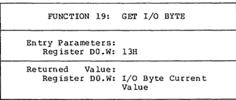
The dec imal BIOS function numbers and the functions they correspond to are listed in Table 4-2.
Number
o
1 23 4 5
6
7
8 9
10 11 12 13 14 15 16 18 19
20
21 22
I
Table 4-2. BIOS Functions
Function
In itialization (called for cold boot) Warm Boot (called for warm start) Console Status (check for console character ready)
Read Console Character In Write Console Character Out
List (write lis·ting character out) Auxiliary Output (write character to auxiliary output device)
Auxiliary Input (read from auxiliary input)
Home (move to track 00) Select Disk Drive Set Track Number Set Sector Number Set DMA Address Read Selected Sector Wr i te Se lec ted Sec tor Return List Status Sector Translate
Get Memory Region Table Address Get I/O Mapping Byte
Set I/O Mapping Byte Flush Buffers
Set Exception Handler Address
[image:23.471.114.389.41.167.2] [image:23.471.52.402.210.493.2]CP/M-6BK System Guide Function 0: Initialization
FUNCTION 0: INITIALIZATION
Entry Parameters:
Reg ister OO.W: OOH
Returned Value:
Reg ister DO. W: User/Disk Numbers
This routine is entered on cold boot and must initialize the
BIOS. Function 0 is unique, in that it is not entered with a TRAP 3
instruction. Instead, the BIOS has a global.label, init, which is
the entry to this routine. On cold boot, Function O-is called by a
j sr init. When initialization is done, exit is through an rts
instruction. Function 0 is responsible for initializing hardware if
necessary, initializing BIOS internal variables (such as IOBYTE) as needed, setting up register DO as described below, setting the Trap
3 vector to point to the main BIOS entry point, and then exiting
with an rts.
Function 0 returns a longword value. The CCP uses this value
to set the initial user number and the initial default disk drive.
The least significant byte of DO is the disk number (0 for drive A,
1 for drive B, and so on). The next most significant byte is the
user number. The high-order bytes should be zero.
The entry point to this function must be named init and must
be declared global. This function is called only once from the
system at system initialization.
Following is an example of skeletal code:
.globl init ;bios init entry point
in it:
*
do any initialization heremove.l i traphndl ,$ Bc
clr.l dO
rts
15
CP/M-68K System Guide Function 1: Warm Boot
FUNCTION 1: WARM BOOT
En tr y Par a me te r s :
Reg ister DO.W: OlH
Returned Value: None
This function is called whenever a program terminates. Some
reinitialization of the hardware or software might occur. When this function completes, it jumps directly to the entry point of the CCP,
named _ccp. Note that _ccp must be declared as a global.
Following is an example of skeletal code for this BIOS function:
. globl _ccp
wboot:
*
do any reinitialization here if necessaryjmp ccp
CP/M-68K System Guide Function 2: Console Status
:b""UNCTION 2: CONSOLE STATUS
En try Parameters:
Reg is ter DO. W: 02H
Returned Va lue:
Reg is te r DO. W: OOl!'FH if ready
Register DO.W: OOOOH if not ready
Th is function returns the sta tus of the currently assigned
console device. It returns OOFFH in register DO when a character is
ready to be read, or OOOOH in register DO when no console characters
are ready.
CP/M-68K System Guide Function 3: Read Console Character
FUNCTION 3: READ CONSOLE CHARACTER
Entry Parameters:
Register DO.W: 03H
Returned Value:
Register DO.W: Charac ter
This function reads the next console character into register
DO.W • . If no console character is ready, it waits until a character is typed before returning.
CP/M-GaR System Guide Function 4: Write Console Character
FUNCTION 4: WRITE CONSOLE CHARACTER·
Entry Parameters: Reg is ter 00. W: 04H
Reg ister 01. W: Character
Returned Value: None
Th is function sends the charac ter from reg ister 01 to the
console output device. The character is in ASCII. You might want
to include a delay or filler characters for a line-feed or carriage return, if your console device requires some time interval at the
end of the line (such as a TI Silent 700 Terminal@ ). You can
also filter out control characters which have undesirable effects on the console device.
CP/M-68K System Guide Function 5: List Character Output
FUNCTION 5: LIST CHARACTER OUTPUT
Entry Parameters: Reg is ter DO. W: OsH Reg ister 01. W: Character
Returned Value: None
This function sends an ASCII character from register 01 to the
currently assigned listing device. If your list device requires
some communication protocol, it must be hanQled here.
CP/M-68K System Guide Function 6: Auxiliary Output
FUNCTION 6: AUXILIARY OUTPUT
Entry Parameters: Reg ister DO .W: 06H Reg ister Dl.W: Charac ter
Returned Value:
Register DO .W: Character
This function sends an ASCII character from register Dl to the currently assigned auxiliary output device.
CP/M-68K System Guide Function 7: Auxiliary Input
FUNCTION 7: AUXILIARY INPUT
Entry Parameters:
Reg ister DO. W: 07H
Returned Value:
Reg is ter DO. W: Character
This function reads the next character from the currently
assigned auxiliary input device into register DO. It reports an
end-of-file condition by returning an ASCII CTRL-Z (lAH).
CP/M-68K System Guide Function 8: Home
FUNCTION 8: HOME
Entry Parameters:
Reg ister DO. W: 08H
Returned Value: None
This function returns the disk head of the currently selected
disk to the track 00 position. If your controller does not have a
special feature for finding track 00, you can translate the call to
a SETTRK function with a parameter of O.
CP/M-68K System Guide Function 9: Select Disk Drive
FUNCTION 9: SELECT DISK DRIVE
Entry Parameters: Register DO.W: 09H
Reg ister Dl.B: Disk Dr ive Reg is ter D2. B: Logged in Flag
Returned Value:
Register DO.L: Address of Selected Dr ive 's DPH
This function selects the disk drive specified in register Dl
for further operations. Register Dl contains 0 for drive A, 1 for
drive B, up to 15 for drive P.
On each disk select, this function returns the address of the
selected drive's Disk Parameter Header in register DO.L. See
Section 5 for a discussion of the Disk Parameter Header.
If there is an attempt to select a nonexistent drive, this function returns OOOOOOOOH in register DO.L as an error indicator. Although the function must return the header address on each call, i t may be advisable to postpone the actual physical disk select operation until an I/O function (seek, read, or write) is performed.
Disk select operations can occur without a subsequent disk
operation. Thus, doing a physical select each time this function is called may be wasteful of time.
On en try to the Selec t Disk Dr ive function, if the· least significan t bit in reg ister D2 is zero, the disk is not curren tly
logged in. If the disk drive is capable of handling varying media
(such as single- and double-sided disks, single- and double-density, and so on), the BIOS should check the type of med ia curren tly installed and set up the Disk Parameter Block accordingly at this time.
CP/M-68K System Guide Function 10: Set Track Number
FUNCTION 10: SET TRACK NUMBER
Entry Parameters:
Reg ister DO.W: OAH
Register Dl.W: Disk track number
Returned Value: None
This function spec ifies in reg ister DO. W the disk track number
for use in subsequen t disk accesses. The track number remains valid
until either another Function 10 or a Function 8 (Home) is
performed.
You can choose to physically seek to the selected track at this time, or delay the physical seek until the next read or write actually occurs.
The track number can range from 0 to the maximum track number suppor ted by the physical dr ive. However, the max imum track number is limited to 65535 by the fact that it is being passed as a 16-bit quantity. Standard floppy disks have tracks numbered from 0 to 76.
CP/M-68K System Guide Function 11: Set Sector Number
FUNCTION 11: SET SECTOR NUMBER
Entry Parameters:
Reg is ter DO. W: OBH
Reg ister 01. W: Sector Number
Returned Value: None
This func tion spec ifies in reg ister 01. W the sec tor number for
subsequen t disk accesses. Th is number rema in s in effec t un t i l
either another Function 11 is performed.
The function selects actual (unskewed) sector numbers. If
skewing is appropriate, it will have previously been done by a call to Function 16. You can send this information to the controller at this point or delay sector selection until a read or write operation occurs.
CP/M-68K System Guide Function 12: Set DMA Address
FUNCTION 12: SET DMA ADDRESS
En try Parameters: Reg is ter DO. W: OCH
Register Dl.L: DMA Address
Returned Value: None
This function contains the DMA (disk memory access) address in reg ister Dl for subsequen t read or wr ite opera tions. Note that the controller need not actually support DMA (direct memory access). The BIOS will use the l28-byte area starting at the selected DMA address for the memory buffer during the following read or write operations. This function can be called with either an even or an odd address for a DMA buffer.
CP/M-68K System Guide Function 13: Read Sector
FUNCTION 13: READ SECTOR
En try Paramete rs: Register DO.W: ODH
Returned Value:
Reg ister DO.W: 0 if no error
Register DO.W: 1 if physical error
After the drive has been selected, the track has been set, the sector has been set, and the DMA address has been specified, the read function uses these parameters to read one sector and returns the error code in register DO.
Currently, CP/M-68K responds only to a zero or nonzero return
code value. Thus, if the value in register DO is zero, CP/M-68K
assumes that the disk operation completed properly. If an error
occurs however, the BIOS should attempt at least ten retries to see if the error is recoverable.
CP/M-68K System Guide Function 14: Write Sector
FUNCTION 14: WRITE SECTOR
Entry Parameters: Reg ister DO.W: OEH
Reg ister Dl.W: O=normal wr ite
l=wr ite to a directory sector
2=wr ite to first sec tor of new block
Returned Value:
Reg ister DO.W: O=no error l=physical error
Th is func tion is used to wr ite 128 byte s of da ta fr om the currently selected DMA buffer to the currently selected sector,
track, and disk. The value in register Dl.W indicates whether the
w rite is an ord inary wr ite operation or whether the there are special considerations.
If register Dl.W=O, this is an ordinary write operation. If
Dl.W=l, this is a write to a directory sector, and the write should
be physically completed immediately. If Dl.W=2, this is a write to
the fir st sec tor of a newly allocated block of the disk. The
significance of this value is discussed in Section 5 under Disk Buffe ring.
CP/M-68K System Guide Function 15: Return List Status
FUNCTION 15: RETURN LIST STATUS
Entry Parameters: Reg is ter DO. W: OFH
Returned Value:
Reg ister DO: OOFFH=dev ice ready Reg ister DO: OOOOH=device not ready
This function returns the sta tus of the list dev ice. Reg ister DO contains either OOOOH when the list device. is not ready to accept a charac ter or OOFFH when a charac ter can be sen t to the list dev ice.
CP/M-6aK System Guide Function 16: Sector Translate
FUNCTION 16: SECTOR TRANSLATE
Entry Parameters: Reg is ter DO. W: lOH
Reg ister D1. W: Log ical Sector Number Register D2.L: Address of Translate
Table
Returned Value:
Reg ister DO. W: Physical Sector Number
Th is funct ion per for ms log ical-to-phys ica 1 sec tor trans lation,
as discussed in Section 5.2.2. The Sector Translate function
receives a logical sector number from register Dl.W. The logical
sector number can range from 0 to the number of sectors per track-I. Sector Transla te a Iso receives the address of the transla te table in
reg ister D2.L. The log ical sec tor number is used as an index in to
the translate table. The resulting physical sector number is
returned in DO.W.
I f reg is te r D 2. L = OOOOOOOOH, imply ing that there is no
translate table, register Dl is copied to register DO before returning. Note that other algorithms are possible; in particular, is is common to incremen t the log ical sec tor number in order to convert the log ical range of 0 to n-l in to the physical range of 1
to n. Sector Translate is always called by the BOOS, whether the
transla te table address in the Disk Parameter Header is zero or nonzero.
CP/M-68K System Guide Function 18: Get Address of MRT
FUNCTION 18: GET ADDRESS OF MEMORY REGION TABLE
Entry Parameters: Reg iste r DO. W: 12H
Returned Value:
Register DO.L: Memory Reg ion Table Address
This function returns the address of the Memory Region Table (MRT) in register DO. For compatibility with other CP/M systems, CP/M-68K maintains a Memory Region Table. However, it contains only one reg ion, the Transien t Prog ram Area (TPA). The forma t of the MRT is shown below:
En try Coun t = 11 16 bits
Base address of first region 32 bits
Length of first region 32 bits
Figure 4-1. Memory Region Table Format
The memory reg ion table must beg in on an even address, and must be implemen ted.
[image:41.469.102.349.55.172.2]CP/M-68K System Guide Function 19: Get I/O Byte
FUNCTION 19: GET I/O BYTE
Entry Parameters: Reg is ter DO. W: 13H
Returned Value:
Register DO.W: I/O Byte Curren t Value
This function returns the current value of the logical to physical input/output device byte (I/O byte) in register DO.W. This 8-bit value assoc ia tes physical dev ices with CP/M-68K' s four log ical devices as noted below. Note that even though this is a byte value, we are using word references. The upper byte should be zero.
Peripheral devices other than disks are seen by CP/M-68K as logical devices, and are assigned to physical devices within the BIOS. Device characteristics are defined in Table 4-3 below.
Table 4-3. CP/M-68K Logical Device Characteristics
Device Name
I
CONSOLE
LIST
AUXILIARY OUTPUT
AUXILIARY INPUT
Charac ter istics
The interactive console that you use to communicate with the system is accessed through functions 2, 3 and 4. Typically, the console is a CRT or other terminal device.
The listing device is a hard-copy device, usually a printer.
An optional serial output device.
An optional serial input device.
Note that a single peripheral can be assigned as the LIST, AUXILIARY INPUT, and AUXILIARY OUTPUT device simultaneously. If no per ipheral dev ice is assigned as the LIST, AUXILIARY INPUT, or AUXILIARY OUTPUT device, your BIOS should give an appropriate error message so that the system does not hang if the device is accessed by PIP or some other transient program. Alternatively, the AUXILIARY OUTPUT and LIST functions can simply do nothing except return to the caller, and the AUXILIARY INPUT function can return with a lAH (CTRL-Z) in register DO.W to indicate immediate end-of-file.
[image:42.471.122.364.58.161.2]CP/M-68K System Guide Function 19: Get I/O Byte
The I/O byte is split into four 2-bit fields called CONSOLE, AUXILIARY INPUT, AUXILIARY OUTPUT, and LIST, as shown in Figure 4- 2.
most s ignifican t least significant
AUXILIARY AUXILIARY
I/O Byte LIST OUTPUT INPUT CONSOLE
[image:43.471.54.381.84.183.2]bits 7,6 5,4 3,2 1,0
Figure 4-3. I/O Byte
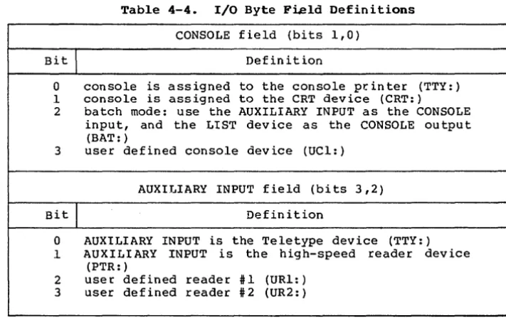
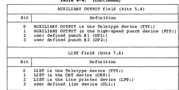
The value in each field can be in the range 0-3, defining the assigned source or destination of each logical device. The values which can be assigned to each field are given in Table 4-4.
Table 4-4. I/O Byte Field Definitions
CONSOLE field (bits 1,0)
Bit
I
Definition0 console is assigned to the console pr.inter (TTY: ) .1 console is assigned to the CRT device (CRT: ) 2 batch mode: use the AUXILIARY INPUT as the CONSOLE
input, and the LIST device as the CONSOLE output (BAT: )
3 user defined console device (UCl: )
AUXIJ ... IARY INPUT field (bits 3,2)
Bit
I
Definition0 AUXILIARY INPUT is the Teletype device (TTY: ) .1 AUXILIARY INPUT is the high-speed reader device
(PTR: )
2 user defined reader #1 (URI: ) 3 user defined reader #2 (UR2: )
[image:43.471.50.406.237.464.2]CP/M-68K System Guide Function 19: Get I/O Byte
Table 4-4. (continued)
AUXILIARY OUTPUT fie Id (bits 5,4)
Bit
I
De fin i tion0 AUXILIARY OUTPUT is the Teletype device (TTY: )
1 AUXILIARY OUTPUT is the high-speed punch device (PTP: )
2 use r defined punch # 1 (UP1: )
3 user defined punch # 2 (UP 2:)
LIST field (bits 7,6)
Bit
I
De fin ition0 LIST is the Teletype device (TTY: )
I LIST is the CRT dev ice (CRT: )
2 LIST is the line printer device (LPT: )
3 user defined list device (ULI: )
Note that the implementation of the I/O byte is optional, and affects only the organization of your BIOS. No CP/M-68K utilities use the I/O byte except for PIP, which allows access to the physical devices, and STAT, which allows logical-physical assignments to be
made and displayed. It is a good idea to first implement and test
you r BIOS withou t the IOBYTE functions, then add the I/O byte function.
[image:44.470.49.415.45.229.2]CP/M-68K System Guide Function 20: Set I/O Byte
FUNCTION 20: SET I/O BYTE
Entry Parameters: Reg ister DO.W: l4H Reg ister Dl.W: Desired
Returned Value: None
This function Uses the value in register Dl to set the value of the I/O byte that is stored in the BIOS. See Table 4-4 for the I/O byte field definitions. Note that even though this is a byte value, we are using word references. The upper byte should be zero.
CP/M-68K System Guide Function 21: Flush Buffers
FUNCTION 21: FLUSH BUFFERS
Entry Parameters: Reg ister DO .W: lSH
Returned Value:
Reg ister DO.W: OOOOH=successful write Reg ister DO.W: FFFFH=unsuccessful write
This function forces the contents of any disk buffers that have been modified to be written. That is, after this function has been
performed, all disk writes have been physically completed. After
the buffers are written, this function returns a zero in register DO.W. However, if the buffers cannot be written or an error occurs, the function returns a value of FFFFH in register DO.W.
CP/M-68K System Guide Function 22: Set Exception Address
FUNCTION 22: SET EXCEPTION HANDLER ADDRESS
Entry Parameters: Register DO.W: 16H
Register Dl.W: Exception vector Number Register D2.L: Exception Vector Address
Returned Value:
Register DO.L: Previous Vector Con ten ts
This function sets the exception vector indicated in register Dl.W to the value specified in register D2.L. The previous vector
value is returned in register DO.L. Unlike the BDOS Set Exception
Vector Function (61), this BIOS function sets any exception vector. Note that register Dl.W contains the exception vector number. Thus,
to se t exception i 2, bus error, th is reg ister con ta ins a 2, and the
vector value goes to memory locations 08H to OBH.
End of Section 4
5.1 Overview
Section 5
Creating a BIOS
The BIOS provides a standard interface to the physical input/output devices in your system. The BIOS interface is defined
by the functions described in Section 4. Those functions, taken
together, constitute a model of the hardware environment. Each BIOS is responsible for mapping that model onto the real hardware.
In addition, the BIOS contains disk definition tables which define the characteristics of the disk devices which are present, and provides some storage for use by the BOOS in maintaining disk directory information.
Section 4 describes the functions which must be performed by
the BIOS, and the external interface to those functions. This
Section contains additional information describing the structure and significance of the disk definition tables and information about
sector blocking and deblocking. Careful choices of disk parameters
and disk buffering methods are necessary if you are to achieve the
best possible performance from CP/M-68K. Therefore, this section
should be read thoroughly before writing a custom BIOS.
CP/M-68K, as distributed by Digital Research, is configured to run on the Motorola EXORmacs developmen t system with Un iversal Disk
Controller. The sample BIOS in Appendix D is the BIOS used in the
distr ibuted system, and is written in C language. A sample BIOS for an Empirical Research Group (ERG) 68000 based microcomputer with Tarbell floppy disk controller is also included in Appendix B, and
is written in assembly language. These examples should assist the
reader in understanding how to construct his own BIOS.
5.2 Disk Definition Tables
As in other CP/M systems, CP/M-68K uses a set of tables to define disk device characteristics. This section describes each of these tables and discusses choices of certain parameters.
CP/M-68K System Guide 5.2 Disk Definition Tables
5.2.1 Disk Parameter Header
Each disk dr ive has an assoc iated 26-byte Disk Parameter Header (DPH) which both contains information about the disk dr i ve and provides a scratchpad area for certain BDOS operations. Each drive
must have its own unique DPH. The format of a Disk Parameter Header
is shown in Figure 5-1.
XLT 0000 0000 0000 !DIRBUF! DPB CSV ALV
32b 16b 16b 16b 32b 32b 32b 32b
Figure 5-1. Disk Parameter Header
Each element of the DPH is either a word (16-bit) or longword
(32-bit) value. The meanings of the Disk Parameter Header (DPH)
elements are given in Table 5-1.
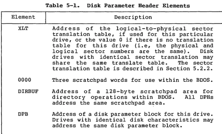
Table 5-1. Disk Parameter Header Elements
Element
I
DescriptionXLT Address of the logical-to-physical sector
translation table, if used for this particular drive, or the value 0 if there is no translation table for this drive (Le, the physical and
logical sector numbers are the same). Disk
drives with identical sector translation may
share the same translate table. The sector
translation table is described in Section 5.2.2.
0000 Three scratchpad words for use within the BDOS.
DIRBUF Address of a 128-byte scratchpad area for
directory operations within BDOS. All DPHs
address the same scratchpad a~ea.
DPB Address of a disk parameter block for this dr ive.
Drives with identical disk characteristics may address the same disk parameter block.
[image:49.474.65.396.125.178.2] [image:49.474.52.406.249.463.2]CP/M-68K System Guide 5.2 Disk Definition Tables
Table 5-1. (continued)
Elemen t
I
De sc rip tionCSV Address of a checksum vector. The BOOS uses this
area to rna in ta in a vec tor of d irec tory check sums
for the disk. These checksums are used in
detec ting when the disk in a dr ive has been
changed. If the disk is not removable, then it
is not necessary to have a checksum vector. Each
DPH must point to a unique checksum vector. The
checksum vector should contain 1 byte for every four directory entries (or 128 bytes of
directory). In other words: length (CSV)
=
(DRM+l) / 4. (ORM is discussed in Section
5.2.3.)
ALV Address of a scratchpad area used by the BOOS to
keep disk storag.e allocation information. The
area must be different for each OPH. There must
be 1 bit for each allocation block on the dr ive,
requiring the following: length (ALV) = (DSM/8) +
1. (DSM is discussed below.)
5.2.2 Sector Translate Table
Sector translation in CP/M-68K is a method of logically renumbering the sectors on each disk track to improve disk I/O performance. A frequen t situation is that a program needs to access
disk sectors sequentially. However, in reading sectors
sequentially, most programs lose a full disk revolution between sectors because there is not enough time between adjacent sectors to
begin a new disk operation. To alleviate this problem, the
tradit ional CP/M solu tion is to create a log ical sec tor number ing scheme in which logically sequential sectors are physically separated. Thus, between two log ically con tiguous sec tor s, there is
a several sec tor rotational delay. The sector translate table
defines the log ical-to-physical mapping in use for a particular drive, if a mapping is used.
Sector translate tables are used only within the BIOS. Thus
the table may have any convenient format. (Although the BOOS is
aware of the sec tor transla te table, its only in terac tion with the table is to get the addre ss of the sec tor transla te table from the OPH and to pass that address to the Sector Translate Function of the
BIOS.) The most common form for a sec tor tr ansla te table is an
n-byte (or n-word) array of physical sector numbers, where n is the number of sec tor s per disk track. Index ing in to the table with the logical sector number yields the corresponding physical sector number.
[image:50.471.62.416.45.269.2]CP/M-68K System Guide 5.2 Disk Definition Tables
Although you may choose any convenient logical-to-physical mapping, there is a nearly universal mapping used in the CP/M community for single-sided, single-density, 8-inch diskettes. That
mapping is shown in Figure 5- 2. Because your choice of mapping
affects diskette compatibility between different systems, the mapping of Fig ure 5- 2 is strong ly recommended.
Log ical Sector
I
0 1 2 3 4 5 6 7 8 9 10 11 12Physical Sector 1 7 13 19 25 5 11 17 23 3 9 15 21
Log ical Sector
I
13 14 15 16 17 18 19 20 21 22 23 24 25 [image:51.470.66.390.125.207.2] [image:51.470.51.417.221.555.2]Physical Sector 2 8 14 20 26 6 12 18 24 4 10 16 22
Figure 5-2. Saap1e Sector Trans1ate Tab1e
5.2.3 Disk Parameter B10ck
A Disk Parameter Block (DPB) defines several characteristics associated with a particular disk drive. Among them are the size of the drive, the number of sectors per track, the amount of directory space, and others.
A Disk Parameter Block can be used in one or more DPH I s if the
disks are identical in definition. A discussion of the fields of
the DPB follows the format description. The format of the DPB is
shown in Figure 5-3.
SPT BSH BLM EXM 0 DSM DRM Reserved CKS OFF
l6b 8b 8b 8b 8b l6b l6b 1Gb l6b l6b
Figure 5-3. Disk Parameter B10ck
Each field is a word (16 bit) or a byte (8 bit) value. The
description of each field is given in Table 5-2.
Tab1e 5-2. Disk Parameter B10ck Fie1ds
Field
I
DefinitionSPT Number of l28-byte logical sectors per track.
BSH The block shift factor, determined by the data
block allocation size, as shown in Table 5-3.
CP/M-68K System Guide 5.2 Disk Definition Tables
Table 5-2. (continued)
Field
I
DefinitionBLM The block mask which is determined by the data
block allocation size, as shown in Table 5-3.
EXM The extent mask, determined by the data block
allocation size and the number of disk blocks, as shown in Table 5- 4.
o
Reserved byte.DSM Determines the total storage capacity of the disk
dr ive and is the number of the last block,
counting from O. That is, the disk contains
DSM+l blocks.
DRM Determines the total number of directory en tr ies
which can be stored on this drive. DRM is the
number of the last directory entry, counting from
O. That is, the disk contains DRM+l directory
entr ies. Each directory entry requires 32 bytes, and for maximum efficiency, the value of DRM shou Id be chosen so that the direc tory en tr ies exac tly fill an in teg ral number of allocation units.
CKS The size of the directory check vector, which is
zero if the disk is permanently mounted, or
length (CSV) = (DRM) / 4 + 1 for removable media.
OFF The number of reserved tracks at the beginning of
a logical disk. This is the number of the track on which the directory begins.
To choose appropria te values for the Disk Parameter Block elements, you must understand how disk space is organized in
CP/M-68K. A CP/M-68K disk has two major areas: the boot or system
tracks, and the file system tracks. The boot tracks are usually
used to hold a machine-dependen t bootstrap loader for the operating
system. They consist of tracks 0 to OFF-I. Zero is a legal value
for OFF, and in that case, there are no boot tracks. The usual
value of OFF for 8-inch floppy disks is two.
The tracks after the boot tracks (beginning with track number
OFF) are used for the disk directory and disk files. Disk space in
this area is grouped into units called allocation units or blocks. The block size for a particular disk is a constant, called BLS. BLS may take on anyone of these values: 1024, 2048, 4096, 8192, or
16384 bytes. No other values for BLS are allowed. (Note that BLS
does not appear explicitly in any BIOS table. However, it
determines the values of a number of other parameters.) The DSM
field in the Disk Parameter Block is one less than the number of
[image:52.469.61.412.49.458.2]CP/M-68K System Guide 5.2 Disk Definition Tables
blocks on the disk. Space is a llocated to a fi le or to the
directory in whole blocks. No fraction of a block can be allocated. block size
The choice of BLS is very important, because it effects the efficiency of disk space utilization, and because for any disk size there is a minimum value of BLS that allows the entire disk to be
used. Each block on the disk has a block number rang ing from 0 to
DSM. The largest block number allowed is 32767. Therefore, the
largest number of bytes that can be addressed in the file system
space is 32768 * BLS. Because the largest allowable value for BLS
is 16384, the biggest disk that can be accessed by CP/M-68K is
16384*32768 = 512 Mbytes.
Each directory entry may contain either 8 block numbers (if DSM
>= 256) or 16 block numbers (if DSM < 256). Each file needs enough
directory entries to hold the block numbers of all blocks allocated
to the file. Thus a large value for BLS implies that fewer
directory entries are needed. Since fewer directory entries are
used, the directory search time is decreased.
The disadvantage of a large value for BLS is that since files are allocated BLS bytes at a time, there is potentially a large unused por tion of a block at the end of the file. If there are many small files on a disk, the waste can be very significant.
The BSH and BLM parameters in the DPB are functions of BLS. Once you have chosen BLS, you should use Table 5-3 to determine BSH
and BLM. The EXM parameter of the DPB is a function of BLS and DSM.
You should use Table 5-4 to find the value of EXM for your disk.
Tab1e 5-3. BSB and BLM Va1ues
BLS
I
BSHI
BLM1024 3 7
2048 4 15
4096 5 31
8192 6 63
16384 7 127