ANALYSIS OF DYNAMIC PERFORMANCE COMPARISON
OF DIFFERENT PWM TECHNIQUES INVERTER FED
INDUCTION MOTOR DRIVES
1S.DINESH KUMAR,2R.VENKATESH,3R.SRIRANJANI,4S.JAYALALITHA
1
PG Scholar, Department of Electrical Engineering, SASTRA UNIVERSITY, Thanjavur 2
PG Scholar, Department of Electrical Engineering, SASTRA UNIVERSITY, Thanjavur 3
Assistant Professor, School of EEE, SASTRA UNIVERSITY, Thanjavur 4
Professor, School of EEE, SASTRA UNIVERSITY, Thanjavur
E-mail:[email protected], [email protected]
ABSTRACT
PWM Inverter fed induction motor drive plays a major role in industrial application such as drilling mills, crane, hoist etc. The major problem in Pulse Width Modulation(PWM) inverter is torque ripple, fluctuation in stator current and transient response of the speed. This paper deals with the modelling and simulation of dynamic performance of various PWM inverter fed induction motor drives in stationary frame. The Induction motor is modeled and stimulated in Stationary frame theory. The steady state and transient response of drive under dynamic load condition is studied and compared with different types of PWM techniques. Space vector modulation fed induction motor drive is compared with various PWM fed inverter drive and the performance is analyzed in MATLAB/Simulink.
Keywords: Pulse width Modulation, Torque, Induction motor, MATLAB/ Simulink.
1. INTRODUCTION
In recent days induction motor drives are commonly used in automation, engineering and household applications. It works on the principle of mutual induction. As the available supply i.e. in
generation, transmission and distribution is
alternating current (AC), induction motors are used in industrial drives. The induction motors out ruled the dc motor because of the following advantages i.e. simple and robust construction, able to operate in any type of environment and less maintenance cost because of the absence of commutators and brushes[1]. Based on construction the induction motors are broadly classified in to squirrel cage induction motor and slip ring induction motor but squirrel cage induction motor is mostly used in industrial drives applications. The Variable Frequency Drives (VFD) plays a major role in industrial and home applications.
For the drives control applications, induction motors are fed from pulse width modulated inverter i.e. by controlling the stator voltage of the induction motor we can able to control the speed of the drives[2].
Pulse Width Modulated inverter fed drives are progressively applied in industrial applications.
There are numerical PWM techniques which can be used to obtain variable frequency and variable
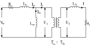
[image:1.595.314.496.532.624.2]
Figure 1: Equivalent Circuit of Induction motor
voltage. No single PWM technique is best suited for all applications[3].
requirements of inverter fed induction motor drives
are harmonics , switching frequency, better dc bus utilization factor and the torque ripples. In this paper modelling and simulation of various PWM inverter fed induction motor drive and two-level diode clamped space vector modulation inverter in stationary theory is compared and its dynamic performance is observed using MATLAB/Simulink. Comparison of dynamic simulation of torque response, stator currents and settling time response of space vector modulation fed induction motor drive and various PWM techniques are presented.
2. MODELLING OF INDUCTIONMOTOR
Induction motor can be modelled using three reference frames theory. Depending upon our applications we can choose appropriate reference frame theory. The major advantages of reference frame transformation is number of voltage equation is reduced and then the time varying voltage equations is changed in to time invariant one[4]. The first step in the modelling of induction motor is to determine the equivalent circuit parameters.
The equivalent circuit elements of the induction motors are obtained from No-load test, DC test, Blocked Rotor test. These tests are carried out to determine the elements of the equivalent circuit – Rsr, Rrr, Xsr, Xrr and Xml[5].
Where Rsr, Rrr are resistances in stator and rotor
side similarly Xsr, Xrr,Xml are stator , rotor and mutual inductances respectively.
In the stationary reference frame the angle theta is zero. In rotor frame the d-q axes rotate at rotor speed. In the synchronous frame the d-q axes rotate at synchronous speed. The general stator and rotor voltage equations of three phase induction motor in arbitary frame are[2]
V
qsr=
R
sri
qsr+
p
D
qsr
+
Ω
D
dsr (1)
V
dsr=
R
sri
dsr+
p
D
dsr−
Ω
λ
qsr (2) (2)
V
qrr=
R
rri
qrr+
(
Ω
−
Ω
rr)
D
drrr
+
p
D
qrr(3) (3)
V
drr=
R
rri
drr−
(
Ω
−
Ω
r)
D
qrr+
p
D
drr (4) (4)where Vqsr is the stator q axes voltage, Vdsr is the
stator d axes voltage .
3. SPACE VECTOR MODULATION
The main advantage of using the space vector modulation is the increased use of dc bus utilization , less harmonics and easier digital realization. In a three phase two level space vector modulation
inverter there is twenty possible
combinations(
6
20
3
=
c
). Out of these twentycombinations there is four illegal combinations for each leg, so for three leg there will be twelve illegal combinations. So (20-12) we will get eight
combinations. The eight different possible
combinations of space vectors
are(000,001,010,011,100,101,110,111).
"1" represents that the upper switch of leg is turned on and "0" corresponds to the lower switch of the leg[6]. The SVPWM generates lesser harmonics in three phase AC voltage which is supplied to the AC motors. It also allows 15.5% increased utilization of the DC bus compared to other techniques. SVPWM can be realized using the following steps
Step 1 :
Convert three phase voltage quantities in to two
phase quantities using the alpha-beta
transformation. Then determine the voltage in alpha axes, beta axes and the reference voltage.
Step 2 :
The second step is to determine time duration of voltage vectors i.e. T1for vector V1, T2 for vector V2, T0 for null vector.
Step 3 :
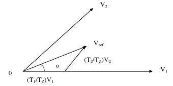
[image:2.595.318.488.577.662.2]The third step is to determine the switching time for each devices.
Figure 2. Reference vector with respect to sector1
3.1 In the alpha axis:
VdcT1+VdcT2cos60=Vrefcos
θ
TS (6)amplitude ratio, a=
dc ref
V
V
V1=V2 = V3 = V4 = V5 = V6 = Vdc (i) substituting (i) in equation(5)
T1+T2cos60=acos
θ
TS (7)T1=
60
sin
)
60
sin(
−
θ
saT
(8)
3.2 In the Beta axis:
substituting (i) in beta axis,
Tssin60=asin
θ
Ts (9)T2=
60
sin
sin
θ
s
aT
(10)
Then
[image:3.595.84.511.86.545.2]T0=Ts -(T1+T2)
Figure 3: Space Vector Pulse Width Modulation Fed Induction Motor Drive
4. SINUSOIDAL PULSE WIDTH
MODULATIONINVERTER
Sinusoidal PWM (SPWM) technique is the well know Pulse width Modulation techniques which is extensively used in the industrial applications.. For the implementation of the SPWM, the frequency of the carrier wave must be greater than the reference sine wave frequency. The intersection of
the carrier wave Vc and the reference sine wave Vr
determines the switching instants and commutation of the modulated pulse In the SPWM inverter the utilization of the DC bus voltage is 78.8%[3].
Figure 4: SPWM Fed Induction Motor Drive
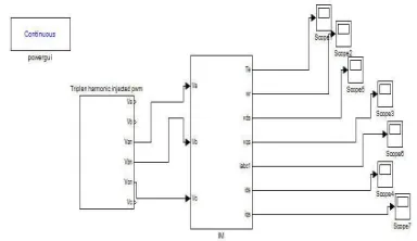
5. TRIPLENHARMONICSINVERTER
[image:3.595.309.501.421.532.2]Induction motor drive fed by Triplen Harmonics PWM inverter is similar to the space vector modulation, but the implementation scheme is different. Triplen harmonic modulation technique increases the DC bus utilization factor to 90.1% which is higher than the SPWM technique.
Figure 5: Triplen Harmonic PWM Fed Induction Motor Drive
6. MULTILEVELINVERTER
separate dc source which may be a
capacitor.
Figure 6: Multilevel inverter Fed Induction Motor Drive
7. SIMULATIONRESULTS
7.1 Dynamic Conditions:
Torque applied to the motor is zero during 0 to 0.7 ms, i.e. the motor is running in no-load condition.
The torque applied to the motor is increased from 0 to 30 N-m at 0.7 ms.
[image:4.595.89.511.73.275.2]During 0.9 ms the torque applied to the motor is reduced from 30 to -30 N-m as a result the torque becomes zero after 0.9 ms.
Figure 7: Torque Waveform Of Space Vector Modulation Fed Induction Motor
Figure 7: shows the simulation of torque response waveform of SVPWM fed induction motor in stationary reference frame with dynamic load conditions. It is observed that during 0 to 0.7 ms the motor is operated in noload condition as a result the torque reaches to steady state . During the time of 0.7 ms the torque applied to the motor is 30 N-m therefore the torque increases. At 0.9 N-ms the torque is decreased to zero as a result the motor runs in no load condition.
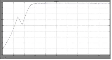
Figure 8: Speed Response Waveform OF Induction Motor Fed By Space Vector Modulation
[image:4.595.305.507.403.499.2]Fig 8: shows the simulation of speed waveform of induction motor in stationary frame with dynamic load conditions. It is noted that at 0 to 0.7 ms the motor is operated in noload condition therefore the speed reaches its rated speed. At 0.7 ms load torque of 30 N-m therefore the torque increases and the speed decreases. At 0.9 ms the load torque is decreased to zero as a results the motor runs in no load condition and the speed increases and reaches the rated speed.
Figure 9: Stator Currents Of Space Vector Modulation Fed Induction Motor
[image:4.595.91.289.466.583.2][image:5.595.95.285.254.353.2]
Figure 10: Torque Response Waveform Of Induction Motor Fed By Cascaded H-Bridge Eleven Level Inverter
[image:5.595.311.503.263.365.2]Figure 11: Speed Waveform Of Induction Motor Drive Fed by Cascaded H-Bridge Eleven Level Inverter
Figure 12: Stator Currents Of Induction Motor fed By Cascaded H- bridge Eleven Level Inverter
Fig.10 shows the simulation results of torque response waveform of induction motor in stationary frame fed by cascaded H-Bridge eleven level multilevel inverter in dynamic load conditions. Fig.11 shows the simulation results of speed response waveform of induction motor fed by multilevel inverter in dynamic conditions.
Fig.12 shows the simulation of stator current waveform induction motor in stationary frame fed by eleven level inverter fed with dynamic load conditions. It is observed that at 0 to 0.7 ms the motor is operated in noload condition as a result the torque reaches to steady state, the speed reaches to rated value and the stator current also reaches to ite nominal value . At 0.7 ms load torque of 30 N-m therefore the torque increases, speed decreases and the stator current increases. At 0.9 ms the load torque is decreased to zero as a result the motor runs in no load condition, speed increases and the
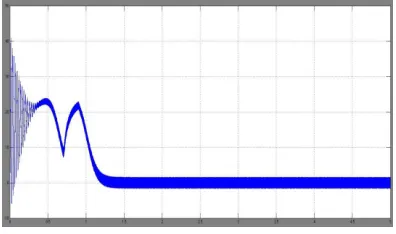
[image:5.595.93.286.382.484.2]Figure 13: Torque Waveform Of Triplen Harmonic Inverter Fed Induction Motor
Figure 14: Speed Waveform Of Triplen Harmonic Fed Induction Motor
Figure 15: Stator Currents Of Triplen Harmonic Inverter Fed Induction Motor
Fig.13 shows the simulation of torque response waveform of induction motor drive in stationary frame fed by Triplen harmonic PWM inverter in dynamic conditions. Fig.14 shows the simulation of speed response waveform of induction motor fed by Triplen harmonic injected PWM inverter in dynamic conditions.
Fig.15 shows the simulation of stator currents waveform of induction motor drive in stationary reference fame fed by Triplen harmonic PWM inverter in dynamic conditions. It is noted that at 0 to 0.7 ms the motor is operated in noload condition as a result the torque reaches to steady state value, the speed reaches to rated value and the stator current also reaches to ite nominal value .
[image:5.595.302.490.392.491.2]decreased to zero as a result the motor runs in no
load condition, speed increases and the stator current decreases to rated value.
[image:6.595.93.288.152.539.2]Figure 16: Torque Waveform Of SPWM Fed Induction Motor
Figure 17: Speed Waveform Of SPWM Fed Induction Motor
Figure 18: Stator Currents Waveform Of SPWM Fed Induction Motor
Fig.16 shows the simulation of torque waveform of SPWM fed induction motor drive in dynamic conditions. Fig.17 shows the simulation of speed waveform of induction motor in stationary frame fed by SPWM inverter with dynamic load conditions.
Fig.18 shows the simulation of stator currents waveform of SPWM fed induction motor drive with dynamic load conditions. It is noted that at 0 to 0.7 ms the motor is operated in noload condition as a result the torque reaches to steady state, the speed reaches to rated value and the stator current also reaches to ite nominal value .
At 0.7 ms load torque of 30 N-m therefore the torque increases, speed decreases and the stator current increases. At 0.9 ms the load torque is decreased to zero as a result the motor runs in no load condition, speed increases and the stator current decreases to rated value.
[image:6.595.307.498.221.499.2]7.2 Induction motor Specifications:
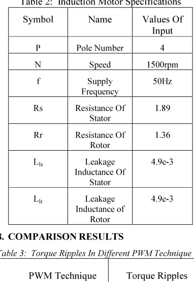
Table 2: Induction Motor Specifications
Symbol Name Values Of
Input
P Pole Number 4
N Speed 1500rpm
f Supply
Frequency
50Hz
Rs Resistance Of
Stator
1.89
Rr Resistance Of
Rotor
1.36
Lls Leakage
Inductance Of Stator
4.9e-3
Llr Leakage
Inductance of Rotor
4.9e-3
8. COMPARISONRESULTS
Table 3: Torque Ripples In Different PWM Technique
PWM Technique Torque Ripples
Sinusoidal Pulse Width Modulation
2.1 %
Multilevel Inverter 18 %
Triplen Harmonic Injected PWM
16 %
Space Vector Modulation 1.3 %
Table.3 shows the torque ripples of induction motor in dynamic conditions with different PWM schemes.
[image:6.595.312.497.225.456.2]
Table 4: Settling Time Of Torque And Speed Response In Different PWM Technique
PWM Technique Torque
Response
Speed Response
Sinusoidal Pulse Width Modulation
2.1ms 2.1ms
Multilevel Inverter 0.6ms 0.6ms
Triplen Harmonic Injected PWM
0.7ms 0.7ms
Space Vector Modulation
0.3ms 0.3ms
Table.4 shows the settling time of speed and torque response of different PWM inverter fed induction motor operated in dynamic conditions. It is observed that the space vector modulation fed induction motor shows faster settling time than other PWM techniques.
9. CONCLUSION
The dynamic performance comparison of different PWM fed induction motor drive shows that the space vector modulation fed induction motor drive produces less torque ripples compared to other PWM technique also the setting time of torque and speed response space vector modulation is much faster when compared to other techniques. The above discussion shows that the Space vector modulation technique is best suited for drives applications in open loop and closed loop system. In Space Vector Pulse Width Modulation the DC bus utilization is also higher when compared to other PWM techniques. The digital realization of the SVPWM is also easier which make it best suitable for drives control applications.
REFERENCES
[1] B.K. Bose. Modern Power Electrics and AC
Drives. Prentice-Hall, Inc., 2002.
[2] R.Krishnan, “ Electric motor drives”, Prentice
–Hall India, New Delhi,2005.
[3] K.V. Kumar, P.A. Michael, J.P. John and S.S.
Kumar, “Simulation and Comparison of SPWM and SVPWM control for Three Phase Inverter,” Asian Research Publishing Network, Vol. 5, No. 7, pp. 61-74, July 2010.
[4] P. C. Krause and C. H. Thomas, “Simulation of
symmetrical induction machinery”, IEEE Trans., PAS- 84 (1965) 1038 -1053.
[5] R.K.Rajput, “Electrical Machines,” first
edition, New York: McGraw-Hill, 1993, pp. 352-353.
[6] J.-H. Youm and B.-H. Kwon, “An effective
software implementation of the space-vector modulation,” IEEE Trans. Ind.Electron., vol. 46, pp.866–868, Aug. 1999.
[7] Keith A. Corzine, Mike W. Wielebski, etal,
"Control of Cascaded Multilevel Inverters", IEEE Transaction on Power Electronics, Vol. 19, No. 3, May 2004.
[8] Adel Aktaibi & Daw Ghani,” Dynamic
Simulation of a Three-Phase Induction Motor Using Matlab Simulink”, IEEE.
[9] B. Ozpineci, L. M. Tolbert, “Simulink
implementation of induction machine model – A Modular approach”, IEEE, 2003, pp 728-734.
[10]J. Holtz, “Pulse width modulation – A Survey”,
IEEE Transactions on Industrial Electronics, Vol. 30, No.5, Dec 1992, pp. 410-420.
[11] J Kup-kai Shayu, Flux compensated DTC of
induction motor drives for speed operation, IEEE Transactions on Power Electronics, vol. 19,No. 6, November 2004,1608-1613.
[12]Deshpande.V, Chaudhari. J.G, Jagtap. P.P,
“Development and Simulation of SPWM and SVPWM Control Induction Motor Drive”,
2009 2nd International Conference on
Emerging Trends in Engineering and