University of Warwick institutional repository:
http://go.warwick.ac.uk/wrap
A Thesis Submitted for the Degree of PhD at the University of Warwick
http://go.warwick.ac.uk/wrap/60657
This thesis is made available online and is protected by original copyright.
Please scroll down to view the document itself.
'rHERMo...ANEMCME'rRY
IN
NAGNETOH '{uRODYNAlUCS
by
David G. Ma.]co Im
A Thesis
submitted to the University of Warwick
for the Degree of Doctor of PhilosophyBEST COpy
AVAILABLE
Variable print quality
ABSTRACT
The problem of developing a reliable technique for measuring instantaneous velocities at an arbitrary point in a magnetohydrodynamic
(MHD) flow of mercury is the primary concern of the thesis. The solution to this problem is urgently needed in order that measurements may be taken in practical MHD devices and in order that the interesting
theoretical work which has emerged in the past decade may be substantiated by experimental evidence.
Much of the information on measurement techniques contained herein will be applicable to other liquid metal flows. The recent advances in the area of constant temperature hot-film anemometry have made this technique the best one for instantaneous measurements in low-temperature liquid metal systems.
TIle thesis is divided into two parts. The study of thermo-anemometry is described in chapter
2
and its application to someMHD
experiments
is
described in chapter3,
Chapter 2 is divided into two main sections, §2. 2 and §2.
3
i whichdiscuss the theory of thermo-anemometry in mercury and demonstrate its
appLl cat.ion in calibration exercises. The hot-film sensors tested are
t.he tiny (0.030 mm di ameter and
0.5
mm length ) quartz-insulatedplatinum film sensors which are now made available for work in electric-ally conducting fluids by Thermo-Systems Inc., St,Paul, Minnesota, U.S.A, An account of our attempts to construct somewhat similar sensors in the laboratory is given in Appendix B.
In addition to discussing various calibration problems, such as
MHD
effects on free convective heat transfer from the hot-film and itsdynamic response, chapter 2 develops, and demonstrates by experiment, new methods for the direct measurement of low turbulence intensi.ties in low Prandtl number fluids. The simple formulae presented are likely to be more accurate in the majority of cases than more sophisticated methods involving linearization of the anemometer voltage with respect to velocity because of their lack of sensitivity to signal drift.
-ii-Chapter
3
discusses theoretical aspects inS3.2
and their experimental substantiation in§3.3
for two different types of MHD flow. The first of these is electrically driven flow in mercury between two circular, highly cOlducting electrodes Which are placed opposite one another in insulating planes with a magnetic field normal to their surfaces. The steady flow is examined theoretically by an asymptotic analysis and exper-Imental.Iy using Pitot tubes and electric potential probes. The experiments give some insight into the behaviour of these probes in MHD situations. This same flow isstudied using a hot-film sensor with good results. This experimmt points to the need for an extensive study of the MHD effects on hot-film heat transfer and the associated MHD errors in measurements for various orientations of the sensor relative to the magnetic field.
Hot-film techniques are then used to examine the instability and subsequent wave-like secondary flow (when the Hartmann number, M, is very high) in this same electrically driven flow. These phenomena are interesting but very difficult to understand. It is shown that
the transverse magnetic field, if strong enough, can control the stability of, and secondary flow
in,
the electrically driven shear layprs through direct action on the most unstable three-dimensional disturbances even though most of the vorticity of these disturbances is parallel to the magnetic field. An attempt is made to discuss the physical mechanism involved.The second tyPe of MHD flow investigated is turbulent vorticity suppression behind a square-array wire grid in a transverse magnetic field. The exper-Iment,is of a preliminary nature but demonstrates some interesting phenomena which can be explained in order of magnitude terms.
Both of the MHD flows studied demonstrete various aspects of the behaviour of the hot-film sensors as well as being interesting in themselves.
The paper listed in the Table of Contents under Appendix A as "Malcolm (1968b)'may be read as an extended sunnnary of the thesis.
-iii-PREFACE
The research presented in the thesis was carried out between October,
1965
and June,1965
at the School of Engineering Science, University of l'larwick0 T1Vhenmy studv of magnetohydrodynamics (MHD)began in September,1965,
it was suggested to me by ProfessorJ.A.
Shercliff that the develop-ment of techniques for measuring turbulence characteristics inMHD
experiments us:ing mercury, and the demonstration of these techniques in some interesting experiments, would be an important endeavour. Theoretical work pertaining to the behaviour of a t.urbul.ei ce field of electrically
conducting fluid when acted upon by ele ctromagnetic forces has occupied the minds of manyapplied mathem~ticians, but direct experimental evidence to test such work has been almost entirely lacking. This initial
prompting led to my study of thermo-anemometryas applied to
MHD
experi-ments in mercury. The success of such a venture seemed hopeful because, firstly, Sajben(1964)
had been successful in operating an insulated hot-wire in mercury and, secondly, an industrial firm, 'lberrno-Systems Inc., U.S.A., had recently been successful in j.roduci.r.g very small, cylindrical, quartz-insulated, hot-film sensor-s whi:~hwould operate in th e constant temperature mode for reasonable. periocs of time in mercury.After
successfully developing t.he technique of constant temperature anemometry to a f'a Lr-Ly re: id.ble sta.te, in both steady and turbulent mercury flows, I wished to test the technique still further by anplying it to some relatively simple but interesting experiments in MED. To this end, I have examined the structure of certain shear Layer-s which occur in electrically driven flow between circular electrodes with the magnetic field nonnal to these electrodes, both in the steady primary flow and in the unsteady flow regime at t.he onset of instab ility.. 'Ibis study inunediately suggested itself f:llowing the collaborative work using different experimental techniques on the same system by Hunt and Malcolm(196S).
I
have also examinedanother- unsteady flow problem, that of vorticity suppression behind a conventional square mesh grid in a transverse magnetic field, as a preliminary attemptto
examine experimentally the effect of electro-magnetic forces on a field of turbulence.-iv-circumstances. A few months elapsed in 1966 while awaiting the long overdue anemometer equipment and the specially designed hot-film probes for mercury. Since then, more months have been anxiously spent awaiting the arrival of new and repaired hot-film probes. The cylindrical hot-film sensors are sufficiently fragile to make a certain runount of
accidental breakage during the course of experiments unavoidable and to greatly enhance the probability of breakage during transit from the place of manufacture in the U.S.A. About
40%
of all probes ordered new or returned for repair were broken either in transit or while clearingCustoms. Since each repair and return journey involved a two-month wait, this situation led to some anxiety!
It was not possible to begin serious experimental work in mercury until the design and construction of the HHD Laboratory, a special
building of plastic construction for MHD experiment.ation in mercury, was completed in the spring of 1967. Nevertheless, I value the experience gained through participation in this project.
No part of this thesis has been presented for a degree at any other
univer-ai.t.v, Copies of three pub Li.catd ons resulting from this work (including the collaborative study discussed below) have been included in Appendix A. One of these is a draft of a paper which is to be
presented at the Sixth Symposium on M3.b'1!st.:;hydrodynamicsin Riga, Latvia, U.S.S.R., in September, 1965. T, .~~ ..aper-is an extended summary of the salient features of the the.s:5"
Some collabo!'o'...i,tt': W(JI1<: was carried out on the problem of electrically
driven flow between (.rrcu.lar- electrodes with Dr.J.C. 'L llurrt between October, 1965 and March, 1966 in a temporary MHD Labor atcry located at Bristol
Siddeley Engines Ltd., Coven t.rv, Th.is Jnve.s t.igat.Lon led to the publication by Hunt and Malcolm (1968). I participated in the experiments and in the analysis of the resullsj but the theoretical analysis was carried out alone
by Hunt., Lxcept where reference s ar-e given to the contrary, the remainder of the ...ror-k described in the thesis is original.
I am very grateful to Professor Shercliff who originally sug~ested the
work and introduced me to the subject of MHD, to my supervisor, Dr.C.J .N.
Alty, for his constant interest .. in the project and many helpful discussions and to m.v colleagues, Dr.,J.C.R.Hunt amd Mr.M.K.Bevir for various
illuminating discus sions on MHD in general. I gratefully acknowledge the help given by Mr.P.Bradshaw at the National Physical Laboratory and by Dr.
D.L.Schultz at the University of Oxford who introduced me to the techniques
-v-of thermo-anemometry.
It must be stated that, without the technical expertness, patience and keen interest of Mr.A.E.Webbin building and modifying apparatus, this work could hardly have been as successful. To him, and to his assistants, Mr.A.Ross and Mr.R.Coles, I am greatly indebted.
I would especially like to thank the members of the Royal Commission for the Exhibition of 1851 who have enabled me to continue my studies here through an Overseas Scholarship and whose encouragement and hospitality has been greatly appreciated. Thanks are also due to the National
Research Council of Canada v.ho provided part of the Schclarship during my
first year.
I am grateful to the University of Saskatchewan, Saskatoon, Canada, who have graciously supported me during the final stages of thesis
preparation, and who have provided a generous travel grant to enable me to present my paper in Riga next month.
Most of the anemometry equipment was purchased from a Royal Society Grant.
Ff.na.Ll.v, I would like to express my sincere a.r,,,re:lab.on to Miss
Jennifer A. Green who prepared the types~r:i~;t ot' L:,e thesis.
The Universit~r "',f ~varwick, Coventry, August, 1968.
-vi-CONTENTS SECTION
ABSTRACT PREFACE
INDEX OF FIGURES INDEX OF TABLES
INTRODUCTION
'I'H:.H.:RMO~ANEMOMETRY IN MERCURY
2.1 Gene.ral Introduction
'I •
2.
2.2 The theory of t.riermo-anemomet.ry in mercury 2.2. -I Heat transfer from cylinders in a steady flow of low Prandt.l number fluid
2.2.2
HHD
effe;:;tson convective heat transfer from cyUnders of finite length2.2.3 Dynamic response of constant temperature hot,-film sensors in unsteady flow
2.2.4 Introduction to Malcolm (1968a) 2.2.5 Sajbenls calibration equation
2.2.6 Sensitivity of F(P-e) to ambient
t
emper-atur-e dr"1ft;:.2.7 The measurement. of small flow
oscillations and low turbulence intensities 2.3 Experiments and Discussion
2.3.1 Apparatus and measurement methods 2.3.1.1
2.3.1.2 2.3.1.3 2.3.1.4
Anemometer and auxiliary equipment Hot-film sensors
The calibration tow tank Measurement methods 2.3.2
2.3.3 2.3.4
MHD effects on free convection Frequency response checks
SECTION
30 SCME MAGNETOHYDRODYNAMIC STUDIES 301 Introduction
302 Theory
302.1 Steady electrically driven flow (EDF) between circular electrodes
302.2 The stability of some shear layers in MHD 3.2.2.1 Introduction
3.2.2.2 MHD equations
3.2.2.3 Direct stabilization of the EDF ve IocLt;y- 'P':~0f~le by E~
v PAGE
-4242
43
4345
45
47
49
3.202.4 mrect ele~tromagnetic effects onthe growth of disturbances
3.2.2.5 Ele~tromagnetic coupling between
the disturbance and the primary flow 3.2.2.6 Ccnclusion
51
3.:203 Decay cl' MHDgYid. bur-bu'Lence in mercury
3. :3
Exper-Iment s and Dis cussion303.1 Nct.es on t.r.e MHD~.aboratory 3.:3.2 Apna:ratu8
57
57
5860
60
643.3.2.1 'The eIe ct.r-omagnet; 64
3. 302.2 Hot--f'Llrn ariemomet.r-y equipment 64
:303.203
'TheEDF
apparatus67
). 3
02.4
The mC!";;' ..fr'Y turmel9Tld grid assembly69
3.3.2.5 l'he flow ct.r-cui.t.
3.3.3
Steady electI'icaUy dri van flow between circular electrodes74
3.3.3.1 The experiment 3.3.3.2 Result s
303.3.3
Discussion3.3.4
Unsteadv electrically driven flow between circular electrodes77
77
78
88
3.3.4.1
The experiment3.3.4.2
Results and Discussion3.3.5
Magnetohydrodynamic suppression of vorticitydownstream from a square-mesh wire grid
111
3.3.5.1
The experiment111
3.3.5.2
Results and Discussion 1143.3.6
A comparison of local velocity measurementtechniques in magnetohydrodynamics 120
90
90
SECTION
4.
CONCLUSIONPAGE
122
REFERENCES 124
APPENDIX A: Publications
A01 Hunt and MalcoJm (1968)
A.2 Malcolm (196Sa.)
A.3 Malcolm (196Sb)
A1
A2A3 APPENDIXB ~ Notes on the design and manufacture of
cylindrical hot-film sensors in the laboratory B1
APPEND'~_XC ~ Experimental details Operating prccedure Tables of data
C1
C4
-ix-INDEX OF FIGURES
FIGURE
PAGE
2.1
Types of hot-film sensors.
2.2
Specification drawing of special Thermo-Systems
hot-film probe for mercury.
2.3
Full size photograph of probe showing hot-film
sensor and mounting prongs.
204
Tow tank calibratjon curve of towing velocity
against added counterweight.
2.5
The calibration tow tank.
2.6
The effects of a magnetic field on free
convection from field-aligned sensors.
2.7
Frequency response test on a 0.030 mm diameter
hot-film sensor by the square-wave test.
2.g
Hot-film probe no.1 calibration curves:
FCP~I)
and
Ft CP~)versus
Ye.
2.9
Hot-film probe no.1 calibration curves:
F(p6)
and
F' (Pe')versus
~Ye.
2.10
Hob-f'LImprobe no. 1 low speed calibration curve: .
F(P~)
and
FtCP;)versus
Pe.
2.11
Hot~film probe no.6 calibration curves:
F(~)
and
F'(~)
versus
p~.2.12
Hot-film probe no.6 calibration curves:
F(~)
and
F'(~)versus
in~.
2.13
Trolle,yvibration.
6
20
21
23
24
2g
30
32
33
34
35
36
39
2.14
Hot-film turbulence signal:
air-mercury interface.
40
2.15
Hot-film turbulence signal:
water-mercury
interface.
40
2.16
Hot-film turbulence signal:
air-mercury interfac~.
41
2.17
Hot-film turbulence signal:
water-mercury
interface.
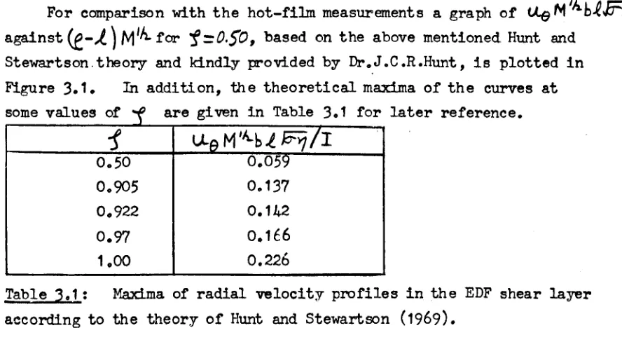
3.1
Theoretical radial profile of azimuthal velocity:
provisional rp~ults from Hunt
&
Stewartson (1969)
for
f
=
0.50.
41
46
-x-FIGURE
3.2
A sketch of the circular electrically-driven
flow system with the systems of co-ordinates.
3.3
The
(x,y, z) co-ordinate system showing the
directions of the wave number vector and the
applied magnetic field relative
to
the flow
direction.
3.4
Sketch of three-dimensional MHD shear l~er.
3.5
Sketch of three-dimensional velocity disturbance
showing circulating disturbance currents and
directions of
j
xi3
forces.
3.6
'Ynenew mercury - MHD laboratory.
3.7
Constant-temperature anemometer and aUJdliary
equipment
asset up for the electrically-driven
flow experinent.
3.8
Sketch of probe-positioning co-ordinate system.
3.9
The electdcally-dri ven flow apparatus installed
in the transV'erse~f'ieldelectromagnet.
3.10
Sketch of the mercury tunnel (Le.
the MHD duct
of Hunt
(1967))with one side wall removed.
3.11The disassembled meroury tunnel and turbulence
generating apparatus.
Theflow circuit.
3.13
3.14
3.15
3.163.17
3.18
3.19
A sketch of th£:: weir tank,
Radial profiles of azimuthal ve IocLty , -::f~.25.
Radial profiles of azimuthal velocity,
f
-:!::().5.
Effects of flow direction on hot-film
sensitivity.
Radial profiles of azimuthal velocity,
.1-::;0.75.
Radial profiles of azimuthal velocity,
J ~
o.
9.
Radial profiles of azimuthal velocity at M=588
at various distances from the electrode.
3.20
Variation of the maximum azimuthal velocity in the
48
48
53
56
6166
68
68
70
71
75
7679
so
S1
82
83
84
shear layer with distance from the electrode.
85
3.21
Radial profiles of azimuthal velocity:
experimental
versus theoretical,
-1
=0.50,
M-390.86
3.22
Radial profiles of azimuthal velocity at
:f
-0.52,
M=588, showing magnitudes of the corrections for
MHD errors.
-xi-FIGURE
3.23 The dependence of critical driving current on Hartmann number in cd.!,,~1.11aI'electrically driven flow9
1
~.502.PAGE
3024 3.25 3.26 3.27
A plot ef
b.
I ver-sus Mo cThe dependence of H on Mo c
Secondary flow at_;:ritical
92 93 95 conditions, M=94, Ic=O.2S arnps.96 Secondary flow at critical conditions,
(a) M ~ 143, le
=
0.44 amps9(b ) M =
153
11 I", = 0.30 amps. '_,3028 Secondary l"lvw at::r'::'tlcal c ono.it.Lons ,
(a) M
--
23;: ? J :~, Go4;~ ampsp
,-'
v
:b) :1 _- ;>:+7SI , 00
53
amp~9ri>
,
M 2".~ I \}046
~ C' )
-
(~ amps.
~
(a)
M .-.484~
1 i0013 amps 9 C(D) H
5A~~
rI020 amps ~
"-- 1
._*
(
.,
\ M- 4?O9
.
• i;" amps.\~/ ~ ~ I
The enset, cflr1slabiUty at M """450, Ic -- 0.99 amps. Secondar v flow wren I '> I_,,~,_, M= 490.
3032
Seconc ar-v YLfW wner. I .>I~
9 M "-""490.
3.33
Ev'ider,ce -::;1 W'aY6 svnme+rv 03.
34 Evide'(,~eoY alig,.lment be+ween the waves and theappli ed magneLl,; f1eld 0
Det.emri.nat.i on. of wave speed 0
Sketch of probable wave-like secondary electrically-driven flow which occurs after critical conditions have been reached in the primary flow.
3.37
Periodic wake behind a square9mesh grid, Nd ~ 2.6,u
=
3.2±
005 cm/se~.3.38 Vorticity suppression behind a square-mesh grid, Nd
=
0.13, NL=
7.0.3.39
Vorticity suppression behind a square-mesh grid of circular cylinders.3.40 Turbulent vorticity suppression behind a square-mesh grid of circular cylinders, Nt
=
7.0,t=
0 atx/L
=
1.3.
oA typical home-made platinum film sensor, d ~ 0.06Ormn. A typical record of the average rIDS voltage which
C.1
corresponds to turbulent fluctuations.
,;g_JDEX OF TABLES
TABLE
201
301
Physical data of hot-film probes 0
PAGE
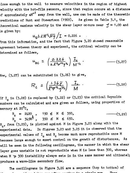
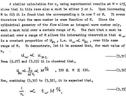
21
Maxima of radial velocity profiles in the
EDF shear layer accor1ing to the theory of
Hur.t. and St.6waTtson (~'969) 0
302 F'L::;"r parameter magn; tu.d6S for the mercury
45
72
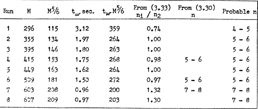
303
Integral wave number- d.eterminat.ions inse.:;e,nda:r:y ELF0
Unpr-oce s sed probe calibration data. Steady ele.:'trl cal:Ly=.i!'iven rLow,
110
C4
C5
1. INTRODUC TION
The problem of devising and applying a sensing element to measure instantaneous local velocities in some interesting steady and unsteady MHD flows of mercury is the concern of this thesis. Many aspects of this problem are relevant in flows of other liquid metals such as sodium or
No...K
eutectic. With these examples, the difficulties are even great.er because of the necessity of using higher operating temperatures.The solution to this measurement problem is urgently required in vrder that the wide gaps between theoretical predic tion and experimental
-verification can be closed. A clear understanding of the behaviour of liquid metal MHD flows in ducts is, of course, of considerable
practical importance in designing electromagnetic pumping facilities to circulate liquid metal coolant in nuclear reactors, etc.
There are four conditions which must be satisfied by an ideal velocity sensing device in MHD whatever its mode of operation These are:
(L) The inherent response time of the sensing element to changing events at its surface must be much less than the short.est time which is characteristic of these changing events.
(ii) The interface region between the sensing element and Lhe changing environment must cause negligible lag and at.tenuation of the changes as they are transmitted to the surfa...:€:of the element,
(iii) The length scale of tbe sensing element must be much smaller than the smallest length scale which is characteristic of the changing envirorunent,
(Lv) Either the length scale of the sensing element must be sufficiently small to make the electromagnetic forces influencing the flow around :it negligible compared to the forces of fluid mechanical origin, or the influence of the electromagnetic forces must be accurately calculable for the length scale employed.
As well as these stringent conditions on the operation of the sensing element, one is faced with deleterious effects due to the phys~cal properties of the mercury environment. Amalgamation readily
-1-takes place between mercury and most other metals, and mercury, being of high electrical conductivity, readily shorts out electrical signals so that direct contact must be prevented between the fluid and the sensing element if this is metallic and electrical~operated.
The measurement device which comes closest to meeting the four desired conditions for accurate velocity measurement while still being sufficiently protected from the environment is a quartz-insulated,
eon stant temperature platinum film mounted on a tiny (as small as .001 Inch diameter) quartz fibre. This sensor is heated and kept at
,(>r~tant temperature e'tect.r-Lcally using conventional constant
t.emper-at.ur-e anemometer equipment. The heat flux transferred by
:'cmvection from the surface of the sensor is related to the local flow ,»ndi tion by idealised theoretical relationships or, more realistically,
f a calibration. Sensors of this type are manufactured by only one f'irm, 'Ihermo-Sys bems Inc , , U.S.A. Attempts to make satisfactory hot-i'ilm sensor-s for mercury have also been made here at cur School of ;;;!"gineering :.3ci",w;e as discussed in Appendix B of this thesis.
Or.ly t.wo pubHcat Lons are known of previous quantitative
inv-estigations of unsteady !'-lliDflows. One is by Branover, Slyusarev
a'1"! Shcherbinin (1965) who employed a strain gauge technique to measure
t.!'!€: fluctuating drag on a tear-drop probe inserted in a turbulent
mer;:'.J!"V flow 0 The size of this tear-drop pr-obe (2.15rrnn diameter)
,:re:;-~'"dE:S t.he measurement of small scale turbulence.
interference by the probe stem, the quantitative r-elationsh f.p between the fluctuating drag force measured and the flt::, +"",,2\, ~ 19 flow ve.Locl,ty at the tear-drop is not at all cl eer 0 T:Jt: aut.ho r-s do not 1 in fact,
claim any great success ,L=' f,it as :1,; erpre Ling their results quantitatively is cUr!c"'~"rled.
In ,,_,:-: " eLl '-',1'j },o.r,1.graph Brancver- et al make the rather curious and unquai ~fJed remark that the t.hermo-anemomet.er-cannot be used in mercury ow-Lngto the smallness of Lhe Prandtl number! Indeed, as will be d:isCUSSea:LL ,-,~tion 2 cf the thesis, the heat transfer characteristics of a fluid of small l:'ard~'.l number enable one to considerably simplify the problem of luw irlte!.,c,: ty t.urbu'len ce measurement by conet ar.'.
temperature anemomet.ry , T:;(' only evi.derrt way in which a small Prandtl number could i71f11i.t:mc~ the t.ur-bu.Ler.ce measurenent capability OJ
-2-anemometryunfavourably is in lowering the frequency response through the thermal inertia effect of the thick thermal boundar-y layer. This effect is minimized by operating the sensor at constant temperature.
The other publication relating to quantitative turbulence measurements in mercury is bJ Sajben (1965) who employed a constant current thermo-anemometric technique. He used a lacquer-insulated tungsten wire in a turbulent jet, subjected to an axial magnetic field, with some success. Since the temperature of the sensor fluctuates in a f'Lucbua tdng flow if the heating current is constant, the frequency response of the hot-~~re is adversely effected by the thermal inertia of ~he therrr~l boundary layer and the insulating coating •
•
For- a discussion of some simultaneous investigations at other
st.It.u td.ons using 'Ihermc--Systems quartz-insulated sensors, which have \>"eryr'ecerrt.l.y been brought to th e author Is attention, refer to the
:ctrod-..:(..:;tury discussi on in section 1 of Malcolm (196Sb) in Appendix A
of this thesis.
"'[hen testing a new experimental technique it is advisable to use rela t,i vely simple experiloontal arrangements , With th is thought in mind
t!V HED studies given in section
:3
of the thesis suggested themselves.The problem of steady electrically driven flow between circular electrodes t.ad prel.riously been investigated by Hunt & Malcolm (196S) (see Appendix A) usi ng Pitot tubes and electric pot.entLal. probes, thus providing
comparabIe results for the steady flow case. In this investigation the control of the experirrent was proven to be extremely edSY.
The exper:i.IOOnton grid turbulence decay in a transverse magnetic field was considered the simplest possible since it required only minor alterations to apparatus already in existence.
It"vi'iS hoped, of course, that these simple experiments would not only test the hot-film technique but would also extend our present under-standing of MHD phenomenain liquid metals, particularly as regards the effects of el.ect.ronagnet.tc forces on stability and on vorticity
suppr-ess Lon in an unst eadv flow.
-3-20 THERMO-ANEMCMETERY IN MERCURY 2.1 General Introduction
Thermo-anemomet~has long been a useful experimental technique in aerodynamics. At the root of all variations of this technique is the fundamental fact that the heat flux convected from a hot surface is a function of the physical properties and the flow velocity of the
surrounding cooler fluid. In order that a hot surface can operate as a velocity measurement device when this function is known, its
temperature or thermal dissipation must be controlled in somemanner. The simplest way to do this is to choose an electrically conducting material for the hot surface and to provide the thermal dissipation and -~ts control electrically.
The hot surface is usually represented in practice by a "hot-wire" or "hot-film". It is also possible to employ thermistor lIEI.terial, as reported by Lumley
(1962),
but problems of poor frequency response and low sensitivity have yet to be solved. The hot-wire sensor is composed of a wire, with a diameter usual~ less than O.01JIDI1.and a length todiameter ratio of a few hundred, which is attached at its ends to electrically condUcting supports. The hot-film sensor is composedof a thin metallic film deposited on a glass or quartz substrate and electrical connections to the fUm to supply the heating current.
For normal use in air the principal advantage of 8 hot.-film sensor
over a hot-wire sensor of similar electrical resistance is its superior strength and rigidity. Whenused in electrically conducting fluids it has the further advantage of being easier to insulate. In seme cases it has proved possible to use a thin coat of lacquer for insulation purposes, but the most satisfactory method available at present is to use a coating of sputtered quartz. Thermo-SystemsInc, , the finn supplying the quartz-insulated cylindrical hot-film sensors for the present r-eaearcr.>' r-eporf that they have not been successful in coating
wires wi.th s puttered quartz. It seems that the wires becomebrittle when coated in this marmer, The difficulty associated with the
insulation of wires by lacquer coatings is illustrated by the fact that, whereas Sajben
(1964, 1965)
was successful, Moreau(1967)
had to abandon the attempt in spite of concerted effort.-4-Hot-film sensors maybe constructed in the laboratory if the necessary equipment am technical skills are available.
B for a discussion of hot-film sensor manufacture.
See Appendix
The two commontypes of hot-film sensor are the wedge and cylinder as shown in Figure
2.1.
The wedge type, first developed by Ling(1955,
1960)
and Ling and Hubbard(1956)
and further studied by Bankoff and RosIer(1962),
is very robust and is without doubt the best sensor for work in low shear hydrodynamic flows where a small flow blockage is of minor importance. However, for minimizing flow blockage whentraversing thin shear layers and for experimmtation in MHDwhere MHD effects on the heat transfer fran the sensor must be minimized, the
smaller, mor-e- fragile cylindrical hot-film recently developed by Thenno-Systems must be employed. The cylindrical hot-film also has another advantage in turbulent flows since an X-array can be constructed (see Figure
2.1),
as in conventional hot-wire anemometry, to measure turbulence intensities simultaneously in two perpendicular directions.The two commonmodes of sensor operation are designat ed as "constant current" and "constant temperature". In both cases the voltage across
the sensor is measured and related to flow velocity. In the constant current mode, the current through the sensor is maintained constant by using a
large resistance in series with it. If the flow velocity in the neighbourhood of the sensor fluctuates, the surface temperature, and hence the resistance, of the sensor also fluctuates. Because of temperature fluctuation the constant current mode is unsatisfactory in hot-film. anemometry; the thermal inertia of the substrate, insulation and boundary layer seriously impair the dynamic response of the hot-film element.
In the constant temperature mode a bridge and feedback system are used to maintain the sensor at constant resistance, and therefore at constant temperature. Constant temperature operation of thin film sensors is superior to constant current operation in allowing rapid response to rapid flow fluctuations.
Anyonewho is interested in learning the basic principles of thermo-anemometrywill find the publications of Kovasznay
(1965)
and Bradshaw and Johnson(1963)
most helpful. Kovasznay's paper includes an excellent bibliography of hot-wire anemometry. Bradshaw and Johnson present a-5-,--_PYREX GLASS SUPPORT
SILVER PLATING-AS CURRENT L.EADS
PLATi N UM HOT- FIL.M
W£DGE-
TYPE
HOT-F'IL.M SENSORPROBE: BODV
!~GOL.D~PLATED STAINLESS 'STEEl...
SUPPORTS AS CURRENT L.EADS
GOL.D PLATING AS CURRENT LEAD
PLATINUM HOT-FILM ON QUARTZ
CYL..INOER
CYl...lNDRICAL-TYPE HOT-FILM SENSO R
<r-_-+l'-- __ VERTICAL SEP"':"RAT,v." OF
.Smm BETWEEN SE~':')RS
X-ARRAY
/~'I'
~I
HOT-Fu.M SENSOR
NOTE:.
FOR USE IN EL-ECTR1CALL.Y' C.ONDUCTING FLUIDS IT IS N!;'C.ESSAR.V TO INSULATE THE HOT-FilM WITH SPUTTERED QUARTZAND THE CURRENT LEADS WITH RESIN.
Fi[Ure 2.1
Types of hot-film sensors.
-6-great deal of helpful information regarding the construction
of hot-wire
sensors and electronic apparatus for signal analysis.
Other good
reviews of hot-wire anemometry are given by Hinze
(1959),
Grant and
Kronauer
(1962)
and Wieghardt and Kux
(1967).
Frey,muth
(1967)
presents a clear and concise study of the operational behaviour of the
constant temperature anemometer.
Rasmussen
(1966)
discusses the ways
by which turbulence characteristics, such as energy spectra and
correlation functions, are calculated from the voltage output of a
constant temperature anemometer.
The present understanding
of the
dynamic behaviour of hot-film sensors is made clear by Bellhouse and
Schultz
(1967)
and Bellhouse and Rasmussen
(196a).
The first known attempt to apply a thermo-anemometric
technique to
mercury was by Lielpeteris
(1960).
He constructed a velocity measuring
probe by positioning an electrically heated, semiconducting element in a
small diameter glass tube adjacent to one end which was closed to
exclude mercury.
Theprobe was inmersed in a mercury flow and attempts
were made to calibrate it.
It was found that the calibration curve
changed from day to day in a peculiar manner and the technique was not
developed further.
The reasons for such strange behaviour would seem
to be those discussed by Sajben
(1964, 1965)
to explain his similar
results obtained using a constant current, lacquer-insulated
tungsten-wire.
He found an explanation by considering the changeable properties
of the non-wetting
layer which surrounds an insulated sensor
inmercury.
He also presented a calibration technique whereby this effect could be
overcome.
This technique is described later in section
2.2.
and applied
in section 2.3.
S.ajben used his constant current technique to measure
the large turbulence intensities in a rrez-curyjet which was subjected to
an axial magnetic field (Sajben
(1967)).
This involved very complicated
procedures of data analysis.
By way of contrast, a very simple
equation is derived in section 2.2 for measuring low turbulence
intensities
(J~u..,
<
0.1,
say) by taking advantage of the constant
temperature characteristic and
tile special convective heat transfer
relations in a low Prandtl number fluid.
To complete this review of previous thermo-anemometrlc
work in
mercury, the work of Fraim
(1966)
and Fraim and Heiser
(196a)
should be
mentioned.
Fraim gained further experience with Sajben's system by
using it as a qualitative instrument to study transition phenomena in a
-7-circular pipe flow of mercury subjected to an axial magnetic field. This chapter on thermo-anemometry is organised in the following manner. Section 2.2 presents the theory of constant temperature
§2.2.1 reviews the relevant work
92.2.2
and2.2.3
discuss MHDeffects anemometry in mercury MHDsystems.on heat transfer from cylinders.
on heat transfer from finite length cylinders and the dynamic response of the cylindrical hot-film sensors to rapid flow changes. These topics are still not well understood and recommendations are made for their further study in chapter
4.
The paper which is designated Malcolm (1968a)p entitled "Someaspects of turbulence measuren:ent inliquid mercury using cY'lindrical quartz-insulated hot-film sensors" , forms an integral part of chapter 2 and is discussed in §2.2.4 to 2.2.7. This work was discussed more informally at the Tenth British Theoretical Mechanics Colloquium at Oxford in.Apri1.,1969.
Sect-ion
2.3
dLscussee the experiments. After a description of the apparatus and method in92.3.1,92.3.2
and 203.3 discuss same preliminary experiments on MHDheat transfer effects and frequency response.§2.3.4 and 2.3.5 discuss hot-film calibration results and results of the experiments designed to test the turbulence equation developed
previously for the case of low Prandtl number fluids.
-8-2.2 The theory of thenno-anenometry in mercury ',
2.2.1 Heat transfer from cylinders in a steady now of low Prandtl number fluid
Although no attempt has been made in thi. s thesis to study in detail the heat transfer from finite-length cylinders in mercury, a few remarks are necessary in order to discuss the observed performance of the
cylindrical hot-film sensors.
The fact that mercury has a low Prandtl number-(
P'2::.
02Sat20
"c.. )
is of primary importance. Since
P
is the ratio of kinematicviscosity, 'V>:
Y!r
,to thennal diffusivity,ex.
z:k/rep ,
a small Prandtl number- signifie s that the diffusivity of momentumis small compared to t herma1 diffusivity. A consequence of a low value ofP
in a flow situation is that the thermal boundary layer is thicker than the velocity boundary layer (eg , see Holman (1968)).The competition between convect.ive heat transport by momentum diffusion and conductive heat transport by thermal diffusion is char-act.er-ised by the Prandtl-Reynolds number product ,
PR,
known as the ~:!let. number,Pe
=
lAdfo.
i which represents the ratio offlow speed t.o thermal diffusion speed. In MHDflows of mercury one ]_s often interested in measuring speeds of a few em/sec. With such now veloci ties normal to hot-film sensors of diameter 0.003 cm
Pe
is less than one.A ther.retic al expression fa!" forced convect.Ien heat transfer, as dascri.bed by the NusseLt number,
N
\A,_ , whi ch is valid cd:. l_owPe
andR
for circular cylinders of infinite length has been der-Lvedby Cole and Roshko (1954) on the basis of the Oseen apprcximet.I.)[, and the assumption of mlifonn surface temperature. ThIs exor-e ssd on is
(i~~
c; - j' )tV',
Pc
-,.._---_..
__
._(2.1)
NIA,
'.
? )r-. 1-..
where
i'
is Euler's constant. Note thatN\A.·-~'>
0
asPe'.-:->O.
This is a result of the infinite length assumption. For qyl1nders of finite Length , the s,:.t.':':li.ionis quite different.N
I.A.... for conduction alone isthen of the same order of magnitude as that calculated fran (2.1) with
?c,./
10-1 Cole and Roshko illustrated this by consideri.ng an ellipsoid as an approximau on for a finite-length qyUnder for whichN
vL ..._I--../.,l-
«
i/I)
in st
aady conducticn when the length to diameterAs
p~~
0 ,
free convection effects also become important. For the small diameters and the t.emperature differences used in this work,tV
I)_.for free convection from infinite-length cylinders is again of the same order of magnitude as
!VIA.
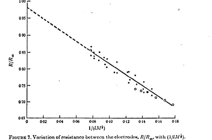
from (2.1) (see Chapman(1967)). Free convection from cylinders of finite length is complicated by three-dimensional effects. The heat transfer from an insulated, cylindrical hot-film sensor is further complicated by end losses to the supports, a nonaunifor.mtemperature distribution, conduction through the insulating layer and the poorly understood effects of the non-orettdng , contact resistance layer which surrounds the sensor in mercury.It is evident, then, that (2.1) is an oversimplification of the practical sit'Ltation. The experiments will show, however, that
fiNiA-is a linear function of
-.l,r,
Pf
fer O.3 ~
p,§ ~ /.0 , although the slope of the line is less than!.
In a recently completed thesis, Hill(1968) has described experiments
ir: IIIThich he examined the directional sensitivity of Thermo-Systems'
c!y:i.i.ndricalhot-film sensors in a steady mercury flow. The principal result of his work is that the proportion of the velocity component along the axis of a sensor inclined to the flow di.rection which contri-butes to the cooling rate varies considerably with flow velocity for a constant angle of inclination. This worl<: should be studied before any attempt is made to use an X-array hot-film sensor in mercury.
2.2.2 MHDe.ffects on c om.~ctive heat transfer from cylinders of f 1nl te lengtn.
MHDeffects on the convecti ve heat transfer fr-,Jm cylinders in mercury at l~ flow velocities are solely due tu the modification of the flow field around the cylinder by electromagnetic forces. This modification takes place because vorticity componentswhich are perpendicular to the magnetic field direction are suppressed (see Shercliff (1965)). The relative importance of electromagnetic forces to inertial forces in the flow is represented in the ratiot../11Rg where
rv1
=
BQcI(O"'/,J~iS
theHartmannrmmber, This ratio is referred to as the interaction
parameter,
NoM
2.... represents the rat io of ele ctromagneti c forcesto viscous forces. It. is not necessary that
N
be very large for significant alteration of the flow field around a cylinder to take place. Leibovich (1967) has sh~n theoretically that there can be noseparation from a rear stagnation point when /\/
=
2. •
This theory isbased on a magnetic field which is normal to the surface. Kalis et al
(1965)
studied the flow around a circular cylinder at lew magneticReynolds number,
Rrn ,
in a transverse magnetic field numerically. They found separation to be prevented atN:=
0,5"
forR:::..
<10 •
They found experimentally that separation was prevented atN:;;
Z forR".::::
I 0
4 in mercury. Another dimensionless ratio,f\1
Y
G
,whereG =
(g et3,.6' ~
T \"1/3 J
is the Grashof number, gives the relative importance of electromagnetic and buoyancy forces. This ratio is important in free convection.
vlhen
electromagnetic farces are similar in magnitude to other forces in the flow one would expect significant e1'fects on the thermaldissipation of hot-film sensors in mercury, if they are orientated so Uat the vorticity of the free or forced convection around thEm is perpendicular to the nagnetic field. Typical magnitudes, considering the
.030
nundiameter sensors in mercury at20 QC
flowing at , mm/sec with an applied magnetic field ofI
Wb)-I1~
areN=-
2,3 ,
NI'::. 0,6,
M'2../
Gt-:::.
8,5 •
MHDeffects must therefore be considered.During the planning stage of the experimental 'WOrkdescribed herein it was decided to eliminate MHDeffects by a.ligning the axes of the. . sensors, and hence the vorticit,r shed by them, with the magnetic field. It was not appreciated until the experiments were well under way that, in the free convection mode, it is not possible to eliminate
iQ1.
electro-magnetic effects on the flOW'around finite-length cylinders in this way.The edge-effects at the ends of the heated film cause free convection currents with some of their·vorticity perpendicular to the magnetic field. This vorticity is strongly dampedby el.ect.r-on.agnet.Lc forces.
Whenvorticity'in the wake of a heated ~ylinder is suppressed by the action of a magnetic field, the convective velocities are reduced. Consequently, the temperature gradients near the surface decrease and the thennal dissipation becomes less. It is expected then that MHD effects wIll cause a reduction in convective heat transfer.
2.2.3, D:mami~r.esponse of constant tEmperature hot-film Sensors in unsteady flew.
In this discussivn it is assumed that the hot-film senscr is heated by a feed back circuit Wfi+..ha gain sufficiently high to keep the hot-film at constant temperature throughout the frequency range of interest.
-11-The most fmportant points to consider are, firstly, unsteady heat transfer between the film and its substrate material because of thermal
feedback from the fluid to the substrate and, secondly, unsteady heat transfer between the film and the thermal boundary layer.
Bellhouse and Schultz (1967) have discussed the first aspect, with particular reference to wedge-type sensors, on the basis of a simple one-dimensional mathematical model. The results of their theoretical investigation are supported by experimental evidence and indicate that the thermal feedback effects are serious in air but not in water and mercury which have lower thermal impedances. These effects are
expected to be unimportant in any fluid for cylindrical sensors in which the fiJJn sur-r-oundsthe cylindrical quartz substrate for a length,)__ , such that
)_/d
»1
,
because direct feedback from the fluid to thesubstrate can only occur at the ends of the film. For practical sensors where
~/d!:ZO
the thermal feedback at the ends may be noticeable in air but not in mercury.The unst.eady heat transfer between the film and the boundary layer involves the insulating quartz layer which is sandwiched between them. This protective coating adds 10 - 20%to the diameter of the sensors
(.030
mm). If one approximates this coating by an infinite slab of sindlar material and thickness, the t.ransient effect of a t.empers.tur-e jump on one side will decay in a time of0(10-
5) sec. The unsteady heat conduction a:ross the insulating coating would therefore have r.egligible effects on the interaction between the fj 1m and the boundary layer.The nature of the film-boundary 1aver I nt er-act.Lon is not well under-stood. It maywell be the must Lmport.ant factor influencing the dynamic response of the sensor. When:\ is 0(1 ()) the velocity boundary layer around a cyll.nder- is not trrin compared to its diameter. When
P<.~/,
the thermal boundary layer is much thicker than the velocity boundary layer. The effect of rapid flow oscillations on heat transfer in such a case has not been adequately studied. Strickland and Davis (1966) have used numerical +echrriques to study this effect in air (P.:;--o·
7)
assuming constant phy.s.i ca 1 properties, small velocity and temperature fluctuations and a constant surface t.emperature. They found the thermal inertia of the fluid at
R-::. : ()
to be twice as high as that predicted by Lighthill (1954) who solved t.he problem on the basis cl'boundary layer approximations. This discrepancy was attributed to failure of the boundary layer assumption that the layer is very thin compared to the diameter of the cylinder. Obviously, boundary layer theory cannot be used to study the case of the much thicker thermal boundary layers in mercury. A nwnerical study along the lines of Strickland and Davis wouldbe very helpful. The effects of the quartz insulation, the contact resistance layer and a non uniform and velocity
'--"
dependent temperature distribution (see Davies and Fisher
(1964))
should be taken into account, if possible.The comnonmethod of checking frequency response in constant temperature anemometryis to introduce a small square-wave voltage across the bridge and to monitor the response of the bridge output vo~tage (i.e. the heating voltage). Whether or not this method of pur.aing the temperature of a snail diameter hot-film sensor adequately descr-Lbes the response of the thermal boundary layer to fluctuations in free stream velocity is still open to speculation. Davies and Fisher
Ci964) have shown in their experiments with hot-wires in air that the
axial temperature distribution on the wire varies with velocity when the mean temperature stays constant. This allows the possibility of
unsteady heat transfer along the wire as the velocity changes. This effect would presumably be more serious in the case of cylindrical hot-films where such a changing temperature distribution would cause fluctuating heat transfer in the axial direction in the quartz substrate, in the quartz coating aOOin the thermal boundary layer. If velocity fluctuations are only snail deviations from the mean (e.g. low intensity turbul.ence ) these effects are probably negligible. The square-wave frequency response check does not take these effects properly into account since the mean temperature is made to fluctuate, but not the shape of the temperature distribution. This fluctuating mean temperature will cause unsteady intera:+icn3 wiLh the quartz substrate and quartz coatings which are unlike those met in practice.
It is expected that the square-wave test will give an approximate indication of the tre quency response to be expected in unsteady flows with low intensity f1u~bl8.tions. It should be noted that, because of lower freest-ream velocitie s being used with sensors of similar spacial resolution, the maximumfrequenry response necessary in liquids is much less than that required in air. In the low speed mercury flow
considered here, for instance, one is Lnt.er-est.ed in frequencies of up
-13-to 0(/0'2) Hoi rather than
JllJ
4)+ltas in air.Before any definite conclusion can be drawn regarding the dynamic response of cylindrical hot-films in mercury, it will be necessar,y to conduct calibrat ion experiments in which unsteady flows of known and variable amplitudes and frequencies can be accurately realised.
2.2.k Introduction to Malcolm(196Ba)
This paper is included in draft fOImlin Appendix A. Its purpose is to discuss the application of constant temperature hot-film
anemometr,yin mercury. After an introductory section, section 2 of the paper reviews Sajben's calibration theory (Sajben
(1965))
and develops simple formulae for measuring low intensity turbulence in fiuids of low Prandtl number. Section3
describes and discusses the results of experiments l-bich test these measurement th eorl ee ,4 draws some conclusions from the results. Twoappendices are included, Appendix A on the effect of environmental temperRture drift on measurement accuracy and Apperrlix B on the details of some special
Section
operational problans.
In the following subsections, §2.2.5 to 2.2.7, the measurement theories are briefly discussed.
The experimental section of the paper will be discussed lAter, in §2.3.4 and 2.3.5.
2.2.5 SaJben 's c;alibration e:guation
Subsection 2.1. of the paper applies Sajben'5 analysis to develop
the steactr flow calibration equation for the cylindrical hot-film sensor. The hot-film sensor is approximated by a V8r,y long laminated cylinder. The thin lamination representing the platinum film is kept at constant temperature. The outermost "lamination" is the non-wetting contact resistance ~er of unknownproperties and thickness Which surrounds the sensor and changes in propertie s each time the sensor crosses the mercury free sur face. The basic heat transfer equation is simply that given in many heat transfer textbooks (e.g. Chapman
(1967))
for radiil heat conduction in a laminated cylinder combined with convective heat transfer at its Burface. This equation, equation (1) in the paper, is rearranged in th e following manner,-14-N
tA([1:)(2.2)
where K contains all velocity independent terms, including the term which describes the contact resistance layer.
The calibration equation, which eliminates velocity independent terms, ,-is written as follows,
I
Nu.(O)
I
Nv.(Pe) •
In practice
Q(pe)
is the ohmic dissipation in the hot-film.An important question is whether or not one would expect similar NP~)curves, for a single senoor, at different values of
LlT.
NiA(Pe)
is given by a temperature independent equation such as
(2.1)
in forced convection. One migtlt expect, however, thatN~{o)
would have some temperature dependence since, in free convection,~J
\A_::'-f (_
p)
G ) ;
where
G
or:..
fJ.
T.
One can calculate tha.t,m.
th a sensor diameter of.0.0)0
mmwhen6T
isO(IC)~C,
PGris0(10-3).
One then observes fromheat transfer data. for horizontal cylinders (e.g. see Chapman
(1967»
that, at such low values ofPG , Nu.(o)
is a very wea.k function of temperature and will appear 'to be const.arrt if changes inLlT
are not too great. Therefore one \\Ould expectF(P~)
curves to be nearlysimilar.
2.2.6
Sensitivityer
i=
(F~)
to~bient temperature dTift Whenmeasuring velocities as low as a few nnn/sec using thet-
(Pe)
calibration, a temperature d..""il'tas low as0./ cC
during the course ofan
experiment can have disastrous effects on measurement accuracy. This problem is studied in Appen:iix A of the paper where the following error equation is dsvekoped to describe t.~is effect.£. -
(f -
1)(
where
ET ~ (ti
1
20-Ll
I.)
/61";
,
fran
6 T
to11
T,
e
I 2..
---(2.4)
and
-15-E
F=
(Fe\. -
'F.r;)/F-r;; ,
the relative error inF(F~)
ifLl
G..
ismistakenly thought by the observer to have remained at
b.
T..
r
may be given the alternative form,2
-
F-
(Pt) / "
t,~L(?
i ,.) )... / . ~ (J (1)/
...'(' i-'"
where
t--r
(Pf)
is Ue true value ofr(;)()
at eitherL)
T,
or.6-r; .
Now, suppose that the particular measurement is being taken at which::=
0.02
(this w:>uldcorrespond appro:xima.telytor=(Pf)=O,j),
and that
D
T
has drifted from ~T. :::
lao
t"to
~-r;
=:20.,
DC
so that~=o.oo5.
Equation (2.4) then shOW'sthatE
F=-
o.Z4.
Thus, ao.
5
% error inA T
has caused a 24%error in~(Pc!)
w-lich, when referred to the calibration curve, gives a correspondingly large error inPe
! It is advisable then to control the ambient temperature very carefully or to employ an electronic temperature compensator which follows the ambient temperature continuously and forces appropriate changes inRS '
the operating resistance of the sensor, to keep .6 T constant.Note that
f
F dt;3creases asET
de~reases andz increases. '!his shows tha.t the temperature drift problem is less acute when measuring largep.~ ,
since 2- is larger, and when the operatingh
T
is increased. L~ general it is ad~isa.ble to keepL\,·
low so as to encourage longsensor life.
2.2.7 The measuI"E!l1entof small flow o9cillations and low tUrbulence intensities
In subsection 2.2 of the paper formulae are developed to enable the direct measurement of low intensity turbulence in mercury. The reader is referred to this subsection for details of the development. This consists of sUDstituting an appropriate relationship for
N~(H~)
and electrica.l quantities forQ(Pe)
in (2.2), differentiating the resulting equation with respectto
the velocity IU
,
normalto
the sensor,substituting the weak oscillat ions in measured voltage and velocity for the differentials and, f'Inal.Ly , taking the rms of the equation in the usual manner, ignoring tbird order infinitesimals.
If (2.1) is used as the relationship for
WIA(Pl) ,
the resulting equation for tile intensity of the streamwise turbulent flt;.ctuatioft1t'·ie-16-where
E
is the mean voltage aero ss the sensor resistance,R
s
,and a resistance in serles with it,R* ,
and )eZ.
is the rms of tlle random voltage fluctuations corresponding to the rms of the velocity fluctuations,_)u?-.
This theoretical equation would probably apply directly in the case of a ver,r long sensor.For finite-length senoors, where the slope of the
I
IN
v...(Pt)
LJ"~. ~Pe
curve is not
-1/2..
but - 5 ,Vlich is determined experimentally from the calibration eqaation (2.3), the resulting formula is--(2.6)
A third fOImula maybe developed for a low Prandt I: number fluid at highPe by substituting for
N~e)
the equation developed by Grosh and Cess (1953) under the assumptions of two-dimensional, inviscid flow, viz. ,N
IJ...= ,.
0
1)-Pe
1/;>_.The formula becomes ,
)c'--<
E.-'
,
---(2.7)
l)-where f
e
is thePeclet
number at the nean velocity,u: .
Note that equat ions
(2.5)
and(2.6)
possess the unique advantage of being independent, not only of the changeable properties of the contact resistance la;yer, but of any reference cordi.t Lon, such asQ (0) ,
so that the eaLeu'latdon of buz-bukenceintensity is independent of signal drift, provided that the drift is on a slower time scale than the time necessary to read )(;.2. a.rrlE.
Note that(2.7)
is not independent of signal drift since?e
must be determined using the calih:rationcurve.
If one retraces the steps in the development of
(2.6)
to the point just prior to tile rms operation, a relationship is found for thecalculation of the amplitudes of small velocity fluctuations which may be caused by, say, a passing eddy, viz.,
-17---- (2.S) u,
Since
e c
<::.E
and i,.A.'c "-
u.,
E"3
andU
haw been approximated byt::. 5 and ~. Equation (2.S) has no importance as far as turbulence measuremerrt is concerned, but it becomes usefuL in calculating velocity
nuctuations in the experiment on the stability of electrically driven flow.
2.3 ExperiIrent s and Discussion
2.3.1 A~ratus gnd measureJrent methoos
2.3.101 Anemometer81'1d au:x::iU.aryequipment
A Therm~ystems Model 1010 constant temperature anemometer was used to operate the special hot-film sensors in mercury. Specifi cations
and operating characteristics of this unit are described by Thermo-Systems
Inc. (1966).
The d,e , component of the ou tput voltage from the anemometer, corresponding to a particular mean flo'W'condition, was read directly
from a Solartron model 1M
1440.3
digital voltmeter. The a.c. component of the output voltage, corresponding to a turbulent velocity fluctuation about the mean, 'W'asmeasured by a Hewlett Packard model H12-34.00Atruerms voltmeter with a frequEnCY response extending down to 2Hz The
rIDS voltage is available at the back of this instrument as a (0 -
1 )
voltd ,c,
output(see
Hewlett Packard(1966, 1967».
For low frequency work in liquids, this d.c. output is conditioned bv switching the damping circui t from the nonnal 2 sec response to a .20 'SM response. Thisamount of damping was still not sufficient to give a sufficiently steady mean nIlS reading. Thed.c. output was therefore displayed on a
Tektronix Model
565
Dual...Beam oscilloscope (containing two plug-in units, a Model%..\61
and a Model 3A3) and recorded by a photographic techniqueo The details of this technique are discussed in Appendix Cand
in Malcolm(196Sa).
Before being fed into tile nns meter the anemometer signal was
usually passed throu~h a 1kHz low-pass filter, thus limiting the noise-level to about Q.3 lIN. This fi ltering was possible since the spatial
resolution of the sensors and the now speeds were such as to limit the measureable frequency range to less than
300
Hz •-1S-To ensure correct operation of the anemometer system the anemometer output voltage was continuously displayed on the oscilloscope.
2.3.1.2 Hot-film sensors
Special quartz-coated platinum film probes for work in mercury were constructed by 'lhermo-Systems Inc. according to their standard procedures for cylindrical sensor construction and the specifications in Figure 2.2. A full scale photograph of the probe end containing the tiny sensor is shown in Figure 2.3.
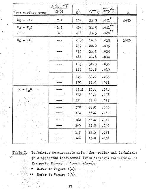
A Nikon V-16 projecting microscope was used to measure the sensitive lengths and approximate diameters of the sensors. Table 2.1 gives
descriptive data pertaining to the three hot-films used in the experiments. The temperature coefficients of resistance entered in the table were
checked experimentally by immersing the sensors in a heated water bath and following the inc reases in resistance with increase in temperature. Resistance was measured using the resistance decks on the anemometer set.
No attempt was made to clean the sensors between runs. It was thought advisable to check the reproducibility of results obtained in this manner since, in practical MHDexperiments, it is extremely hard to ensure cleanliness in the system.
2.3.1.3 The calibration tow tank
A special tow tank was designed and constructed for the purpose of calibrating hot-film eensor s in mercury. This tank is formed of rigid pvc sheet,3/16-inch in thickness, to make a trough of internal dimensions, 4 x 4 x 54· inches. It is supported in a steel framework to eliminate deformation of the tank l'hm it is filled with about 4cxfb of mercury.
The hot-film probes are suspended from a "f-b brass trolley so as
to
pass through the mercury free surface with the sensors horizontal. The trolley runs above the tow tank on two-t-
inch diameter stainless steel rails. It has three wheels, approximately2i,
inches in dia-meter, which are formed from pvc material to assist in the damping of vibrations in the mechanism. Twowheels on one side resemble V-pulleys and serve to guid the trolley on one of the round rails. The third wheel has a flat running surface and rides freely an the other rail.This arrangenent of guide wheels minimizes wheel chatter and eliminates the need for accurate posit ioning of the rails.
-19-U.OF WARWICK MHO lAOORA'mRY'
3/5/66
J:
I
S):tlit
bet we."" PiU{SPLlT
Pn~
COt-lTACTS~)'t1vsthe~icll£a.r TO FIT MODEL.
1170
STD .. to.OOjD~en.so~.
MINlATURE
PROBE
SUPPORTSTAINLESS STEEL..
.iao
QCNON-SoLOER£~L£AKPROO'
JOlln.~
~-
...
STAINL.E.SS STEEl.. .059Q
ITop
VIEW OF
Sf:NSOR SCAL.E:Z: ,
1.001
D
QUAR;Z-COATE:O PLATINUMI
HOT-FILM SENSOR WITH.020
SENSlTIVE l£NGTH0590.0•
•
NOTE:
r,
INSUL.ATE PROBE' FOR US£'IN W,C:RCURY.
2..
PROae MVST WITHSTANDOPERATIO~ AT
100·C.
3.
ALLDJME"NSIO~SAR~
IN
INC.HES.la
4
D.G.MALCOL.M
SI
NG-LE: SENSOR HOT-FILMPROSE:Pieure 2.2
Specification
drawing
of special
Thermo-Systems hot-film
probe:" for mercury.
-20-Figure 2.3 Full size photograph of probe showing hot-film sensor and mounting prongs.
•
Probe Approximate Sensi tiv.e Approximate Temperature number sensor diameter length distance be- coefficient
in mm in mm tween tips of of resistance
nron.Q's in mm .Ln
O_e_-1
0.030
:!:0.003
0.452 : 0.015
1.13
0.00274
2
0.030 - 0.003
+0.495 - 0.015
+0.95
0.00236
6
0.028 - 0.003
+0.478 - 0.015
+1.42
0.00236
Table
2.1
Physical data of hot-film probes.--21-The trolley is towed via a system of pulleys and steel cables by a 2- inch Q.D. hollow brass cylinder, with a sharp-edged orifice at one end, which descends vertically under gravity in an accurate~ machined
stainless steel tube,
7
feet in length, .through a mixture of water and eomnonwater-soluble machining lubricant. The rate of descent is fixed by the pressure drop across the 0.1-inch diameter orifice. Slower speeds are obtained by adding counterweights to a restraining cable which is attached to the "'ear of the trolley. The variation of speed with counterweight is shown in Figure 2.4. This method can be used toachieve trolley speeds as low as O.2em/sec. Hi€f1er speeds than 0.9 cm/sec are obtained by adjusting a by-pass valve to regulate a by-pass flow
from the bottom to the top of the stainless steel tube during the descent of the brass cylinder. The trolley is timed over a 50 em distance by a Griffin Centisecond. Timer lllieh is actuated by the tripping
ot
microswltches situated on one guide rail at either endot
the 50 cm length.A similar towing technique was used by Lindgren and Chao (1967) who covered a range
ot
speeds by installing.orifices of various sizes,one for each speed,' in the driving cylinder. The by-pass. arrangement used in the present case seems a 'WOrthwhilesimplification. 'ilie
apparatus is capable of speed regulation from 0.3
to
14 em/sec ld th±
0.5% precision ani with sufficiently low vibration in the mechanism to produce an equivalent turbulence intensity of 0.015•
Mostot
this vibration apparently arises fran harmonic oscillations in the towing cables which are excited by a slight binding of the brass cylinder as it slides within the stainless steel tube.
*
'ilie two/tank was also used
to
produce a turbulence field in order to test the turbulence measurenent fonnula which was developed in §2.2.7.
This was accomplished by mounting a conventional square-mesh grid of round rods P.02S in. diameter rods,0.150 in. mesh spacing) on the trolley at a fixed distance ahead of the hot-film sensor and towing the entire assembly along the tank at constant speed.Figure 2.5 shows the trolley traversing the 50 cm test length between the microswitches with the probe cable in plAce but without
*
This binding problem can probably be corrected by ski.mmingapproximately 0.001 inch off the diameter of the brass cylinder before future use.-22-
----/~
"",-.
v
/
J•
: ! I I II
/
I I ~J
.
.
I
0 CO ~ ~ N
...I
ti
ti
0.
0
j3S/Wj
NI 11-~
-23-
---\J') •""
o '. <""\ lJ).
No
.:
N CO·
-....I' I<:1
-!
\--..i
11)
::x:
I ..: ~! --jlu
~!
~!
4.Ij oI-
i
igure 2.5, h~ calibration tow tank.