735
©IJRASET: All Rights are Reserved
Automation of Milling and Drilling Machine using PLC
Sukanya H N1, Kishorini M C2
1
Assistant Professor, Department of Electrical & Electronics Engineering, PES College of Engineering, Mandya, India
2
Assistant Professor, Department of Electrical & Electronics Engineering, GSSSIETW, Mysuru, India
Abstract: The conventional machines become phenomenally productive and flexible by retrofitting them with automated controllers. Refurbishing and up-gradation of old machines evoke them close to their original performance levels. Today, the concept of remanufacturing machine tools is emerging. Additionally, these cost-effective solutions of automation are equally beneficial to small, medium and large industries. Industrial automation is largely based on PLC-based control systems. This paper highlights a case study on retrofitting and automation of a milling and drilling machine for successful performance with increased productivity and better accuracy by interfacing with HMI. Technological up-gradation in MSME sector can be brought about suitably by retrofits and automation for cost effectiveness and higher productivity.
Keywords: Retrofits and Automation, Programmable Logic Controller (PLC), Human-Machine Interface (HMI), Micro Small and Medium Enterprises (MSME)
I. INTRODUCTION
Now-a-days rapid growth in technology has come-up with different solutions such as PLC, SCADA, DCS, Microprocessor and Microcontrollers, which will fulfill all the requirements of the industrial processes through automation. It requires a conscious effort on the part of plant managers to identify areas where automation can result in better deployment ,utilization of human-machine-interface and its implementation to achieve higher productivity It could be a phased approach from the perspectives of comprehension or step-by-step approach to automate understanding the needs thus employing control systems engineered to one’s specific requirements that would achieve the most attractive results Automating the manufacturing industry would add phenomenal value to the MSME sector. The retrofit is an attempt of ethnic and advanced solution to contain the capital costs and add value to the processes by mix and match of inexpensive available technological inputs to result in improved quality at a lower price[1]. Hence market life of products can be increased by absorbing technology through retrofits to addresses obsolescence. Upgrading the existing machines through retrofits can bring many benefits of new equipment at a fraction of the cost. Much of the savings depends on the application. For example, if the control circuitry and selection represents 10 to 20% of the machine value, and its replacement just would give a new-machine of same performance, the machine owner would save 80% of capital cost of new machine purchase. This justifies retrofitting the machine by changing the state-of–the-art of control circuitry[2].
II. AUTOMATION AND ITS ADVANTAGES
Industrial automation uses computers and controllers to control industrial machinery and processes to enhance productivity and delivery of services. Automation greatly decreases the need for human sensory and mental requirements. The impact of automation in industries is as follows:
1) Increase productivity and reduce cost.
2) Emphasis on flexibility and convertibility of manufacturing process.
3) Increased consistency of output.
4) Replacing humans in tasks carried out in dangerous environment.
III.OVERVIEW OF THE PROJECT
The aim of the project was to retrofit and automate a Milling and Drilling Machine using PLC. During the preliminary phase of project, the machine was found to be operated manually. The main objective set for the project was to design, develop and implement an automated controller for the machine in order to upgrade the technology[3]. The major steps in achieving this objective are as follows.
1) Inspection of the machine to identify the areas that we can automate.
2) Assembly of the machine
3) Design the control circuit for automation of the machine as per the requirements.
4) Build the control panel as per the designed control circuit by proper selection of equipment.
5) Developing Automated control program using PLC software
736
[image:2.612.183.428.117.284.2]©IJRASET: All Rights are Reserved
Figure 1. Control Scheme of the Milling and Drilling Machine .
A closed-loop control system for variable speed operation is configured with input signal via limit switches and the induction motor drives the load[5]. The PLC monitors and controls all the input / output devices through HMI.
V. HARDWARE DESCRIPTION The whole project hardware can be divided into two main categories.
A. The machine with limit switches and induction motors.
B. The Control panel with accessories.
[image:2.612.206.410.407.702.2]737
[image:3.612.192.406.88.241.2]©IJRASET: All Rights are Reserved
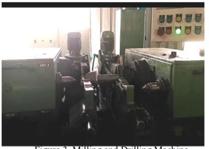
Figure 3. Milling and Drilling Machine
1) DVP-14SS211R Programmable Logic Controller: The DVP- 14SS211R features high speed counters, a flexible serial port, real-time monitoring and an expansion bus that allows matching modules to be mounted on the right side of the PLC without external wiring.
2) Text Panel: The screen of this series can display two lines / four lines text or message at the same time. It not only has the features of light weight, cost-effective price, good flexibility in use, and easy-to-control operation, but also supports various communication protocol. This project uses delta TP02G panel.
3) Switch Mode Power Supply (SMPS): A switch-mode power supply (SMPS) is an electronic circuit that converts power using switching devices that are turned on and off at high frequencies, and storage components such as inductors or capacitors to supply power when the switching device is in its non-conduction state.
4) Two Pole MCB: MCBs are used to protect plants in buildings and for industrial applications. The devices can be used as main switches for the disconnection or isolation of plants. The devices are approved for use according to IEC standards for systems up to 250/440 V AC. when overvoltage or overcurrent occurs it will break both phase and neutral.
5) Contactor: A contactor is an electrically controlled switch (relay) used for switching an electrical power circuit. A contactor is typically controlled by a circuit which has a much lower power level than the switched circuit, such as a 24-volt coil electromagnet controlling a 230-volt motor switch.
6) MPCB: A Motor Protector Circuit Breaker, as the name indicates, is used for protection against overvoltages and over currents in electric motors. This type of electric protection device is used in several industrial and commercial applications.
7) Pushbutton Units and Indicating Lamps: The 3SB5 series is a modular range of commanding and signalling devices for front panel mounting and rear conductor connection. The devices are of modern industrial design and can be mounted rapidly by a single person. The operating surfaces of the pushbuttons and illuminated pushbuttons are concave. The lenses of the indicator lights are convex.
8) Limit Switch: A Limit Switch is enclosed in a case to protect a built-in basic switch from external force, water, oil, gas, and dust. Limit Switches are made to be particularly suited for applications that require mechanical strength or environmental resistance. It gives output when it mechanically touches an object.
9) Induction Motors: In the project ten Induction motors (also known as asynchronous motors) are used for different purposes. The 7.5kw rated motor used in milling process, the 1.5kw motor is used in drilling process and 0.75kw motor is used for clamping are connected to PLC for control purpose. The other is 0.37kw rated motor used in machine to pump the oil for lubrication purpose
10) Relay Board: One of the most common types of outputs available is the relay outputs. A relay can be used with both AC and DC loads. Each relay draws approximately 20mA from the +24V power supply when energized. Typically a diode, resistor or other snubbed circuits are used to prevent any damage to the relay. In project, all the outputs of PLC are connected to output devices through relays of relay logic board and few are left unused for future expansion options.
738
©IJRASET: All Rights are Reserved
Press clamp push button
Clamp motor is ON, Clamp the work piece
Check for home condition
Select unit A or unit B or
both
Adjust for home position Cycle Start
The ladder diagram is converted into binary instruction codes so that they can be stored in random-access memory (RAM) or erasable programmable read-only memory (EPROM). Each successive instruction is decoded and executed by the CPU. The CPU controls the operation of memory and I/O devices and to process data according to the program. The method for the direct representation of data associated (for Delta PLC’s) with the inputs(X), outputs(Y), Memory(M), Timer(T), Counter(C) and Data Register(D) is referenced directly using X, Y, M, T,C and D respectively. In the project, programming of PLC is done using WPL Soft 2.33 version software (suitable for programming all types of Delta DVP Series PLC’s). This software integrates all the modules connected to the PLC and the devices connected to its HMI, Induction motor. Also the monitor and control are through HMI. WPL Soft 2.33 - WPL Soft is a program editor of Delta DVP series PLC for WINDOWS computers. In addition to general PLC programming and WINDOWS editing functions (e.g. Cut, paste, copy, multi-window display, etc) WPL Soft also provides various comment editing as well as other special functions (e.g. register editing and settings, file accessing and saving, contacts monitoring and setting, etc) .
TPEditor 1.88- TPEditor is programming software for Delta text panels operating on Windows. What users see on the screen of a computer is what they get on the screen of a text panel. Users can immediately see what they design on the screen of a computer. The image displayed on a screen of a computer is the same as the image displayed on the screen of a text panel. The programming adopted by TPEditor is object-oriented programming [6].
739
©IJRASET: All Rights are Reserved
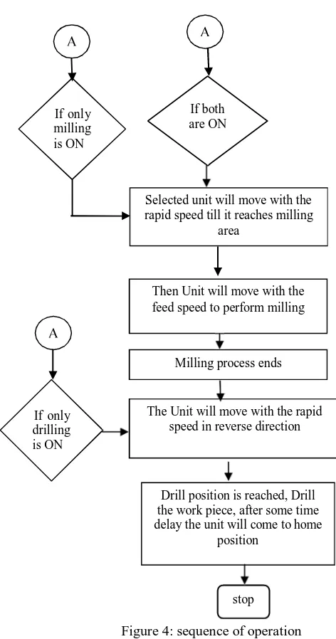
Figure 4: sequence of operation
VII.SIMULATION RESULT
[image:5.612.164.400.87.536.2]The simulation results are illustrated in Figure 5 in which the milling and drilling machine operations are discribed using the developed ladder logic.
Figure 5: Ladder diagram for milling and drilling machine to initialize the process stop
Drill position is reached, Drill the work piece, after some time delay the unit will come to home
position If only
milling is ON
If both are ON
Selected unit will move with the rapid speed till it reaches milling
area
If only drilling is ON
The Unit will move with the rapid speed in reverse direction
740
[image:6.612.167.442.114.309.2]©IJRASET: All Rights are Reserved
Figure 6: Production rate comparison
The above bar chart (figure 6) which presents the production comparison in numbers for both manual and automatic running machine. The comparison is with respect to Production Rate. It is found that the machine running automatically has improved production rate, i.e. the number of components which are processed manually are approximately
88 in 8 hours. In case of automation the components are approximately 144 in 8 hours. Which clearly indicates that the production rate in automation process is increases to about 40%, which in turn indicates the overall work efficiency is increased in huge number and the accuracy is tuned to the best level. Finally, the verified results were satisfactory and accepted by the company, thereby inferring that the automation of the machine is successful.
VIII. CONCLUSION
In this study, the milling and drilling machine was automated using ladder logic in PLC. Thus it reduces the human error, Increases productivity and Reduces setup time. The efficiency of the system is increased and also accuracy can be tuned well.
IX. FUTURE WORK
Though the automation of the machine was found to be successful, the machine operation mainly depends on the Induction Motor and gear systems associated with it. Due to gear systems in the machine, there will be mechanical wear and tear in the system. Therefore, it is recommended to replace the induction motor by a servo motor, this will eliminate the wear and tear in the machine and also yields high level of accuracy and increase the production and reduce the maintenance cost. The system can also be automated by SCADA and IOT.
X. ACKNOWLEDGEMENT
The authors would like to thank Mr. Sunil Manjunath.V. Managing Partner of the MAS Automation.
REFERENCES
[1] Abhi Chaudhary, Tasmeem Ahmad Khan, Amit Raj Varshney, IJSET, ―Value Addition to Senescent Machine Tools through Retrofitting‖, International
Journal of Scientific Engineering and Technology (ISSN : 2277-1581) Volume No.2, Issue No.7, July 2013.
[2] Nikulin O.V, Shabanov V.A. ―Improving Reliability of Drill Rig Electric Drive Control System‖ International Conference on Industrial Engineering,
Applications and Manufacturing (ICIEAM), 2017.
[3] P.A. Mehta, A.A Sagare, V.S Samse, Dr. A.D. Rahulkar―Automatic Drilling system using PLC‖ International journal for Technological research in engineering, March 2014.
[4] D. Sowmiya, ―Monitoring and Control of a PLC Based VFD Fed Three Phase induction Motor for Powder Compacting Press Machine‖, 978 -1-4673-4603-0/12/ IEEE, 2012.
741
©IJRASET: All Rights are Reserved
AUTHORS PROFILE
Ms.Sukanya H N is Assistant Professor in the Department of Electrical & Electronics Engineering.She has received her M.Tech. from NIE, Mysuru and B.E. from PESCE, Mandya ,Karnataka,India
Ms.Kishorini M C is Assistant Professor in the Department of Electrical & Electronics Engineering.She has received her M.Tech. from NIE, Mysuru and B.E. from GSSSIETW, Mysuru, Karnataka,