Physics-of-Failure Lifetime Prediction Models
for Wire Bond Interconnects in Power
Electronic Modules
Li Yang, Pearl A. Agyakwa, and C. Mark Johnson,
Member, IEEE
Abstract—This paper presents a review of the commonly adopted physics-of-failure-based life prediction models for wire bond interconnects in power electronic modules. In the discussed models, lifetime is generally accounted for by loading temperature extremes alone. The influence of the time spent at temperature on bond wear-out behavior and damage removal phenomena result-ing from thermally activated processes is not addressed. The phe-nomenological considerations based on some unusual observations highlight the need for new approaches to wire bond life prediction models and thus motivate the proposal of a new time-domain damage-based crack propagation model.
Index Terms—Physics-of-failure model, power electronic mod-ule, reliability, wire bond.
I. INTRODUCTION
P
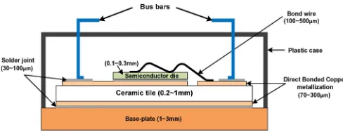
OWER semiconductor modules are the core components in most of the power electronic systems, playing a key role in delivering flexible and efficient energy conversion. The reliability of these integrated power devices is critical to the overall performance and life-cycle cost of a power electronic system and even the whole power system. Therefore, a de-tailed understanding of the factors influencing the reliability of power electronic modules is becoming an increasingly impor-tant topic.The primary reliability concern in power modules arises from the fact that they consist of materials with different ther-mal expansion coefficients, which causes therther-mal mechanical stress in adjacent layers under time–temperature exposure. The performance of these modules is greatly limited by stress-induced failures in the packaging materials [1]. Fig. 1 illustrates a schematic multilayer structure of a typical Direct Bonded Copper ceramic substrate power module.
In such a module, semiconductor dies are solder mounted on electrically insulating substrate, which is in turn soldered to a base plate. Electrical connections are made to the bot-tom terminal of the semiconductor devices via conducting metallization layer on top of the ceramic substrates. Metal wires are ultrasonically bonded to connect the top terminals
Manuscript received July 18, 2012; revised December 17, 2012; accepted December 17, 2012. Date of publication December 21, 2012; date of current version March 7, 2013.
The authors are with the Department of Electrical and Electronic Engineering, The University of Nottingham, Nottingham NG7 2RD, U.K. (e-mail: [email protected]; [email protected]; [email protected]).
Color versions of one or more of the figures in this paper are available online at http://ieeexplore.ieee.org.
[image:1.594.302.546.195.289.2]Digital Object Identifier 10.1109/TDMR.2012.2235836
Fig. 1. Schematic cross section of a power module.
of the semiconductor device to external bus bars. The cavity of the shell is filled with silicone gel and is covered with a plastic, snap-on lid. Bond wires form the electrical connections between the semiconductor chips and the module substrate. Wire bond interconnect failure is one of the most important life limiting factors to the reliability of these modules [2]. Therefore, lifetime prediction for wire bonds is crucial to the reliability design and assessment of the whole module.
Selection of the approach to reliability design and prediction for electronic products has been an evolutionary and con-troversial process. Quality and reliability engineers used to adopt standardized stress-based methodology for qualification test and life assessment [3], [4]. Nowadays, reliability assess-ment based on physics-of-failure (PoF) knowledge is finding widespread application in power electronic products.
The PoF approach aims to identify the root cause of the potential failures and set up links between failure mechanisms and the lifetime under specified operation conditions, through the use of stress and damage models [5], [6], which facilitates a more meaningful life prediction approach. Moreover, lifetime behavior can be assessed with respect to new packaging materials, new configuration or manufacturing processes to provide information as to the improvements in their reliability. Therefore, the PoF-based methodology is not only a reliability prediction tool, but also a reliability enhancement technique. In addition, the application of PoF models in prognostics and health management allows the remaining life of an individual power module to be evaluated in the real-time operational environment and hence benefit system reliability and maintenance [1].
In the PoF methodology, the development of an effective physics-based model makes as critical a contribution to an accurate reliability prediction as the identification on the failure mechanisms, and remains the subject of extensive research for ultrasonic wedge bonds.
In the section which follows, the existing lifetime model representations in the literature, including simple acceleration models and detailed physical models are listed and briefly described. Their limitations are discussed in the subsequent section, with the view to highlighting areas which require fur-ther understanding and investigation. Modifications to existing methods are suggested and a new way of approaching wire bond lifetime assessment is proposed.
II. OVERVIEW OFSTATE-OF-THE-ARTLIFETIME PREDICTIONMODELS FORWIREBONDS
Wire bond failure is largely attributed to thermomechanical fatigue caused by (1) repeated flexure of the wire (2) shear stress between bond pad and wire. These consequently induce vertical heel cracks or horizontal cracks at the bonding interface.
The most common plastic strain-based fatigue model is based on the Coffin–Manson relationship which defines a power law relation between number of cycles to failureNfand the plastic
strain induced per cycle(εpl)for low-cycle fatigue [7], [8]
Nf =C1(Δεpl)−C2. (1)
The value of plastic strain can be estimated by finite-element analysis (FEA) or by numerical calculation as a function of wire loop curvature. One of the earliest attempts at this approach to lifetime prediction of wire bond interconnects was illustrated in [2]. This approach can provide a useful tool for comparative evaluations and parametric studies of different materials and geometries. But the corresponding model validation can be difficult as the plastic strain is not a straightforward parameter to measure in experimental tests. In [9], the predicted lifetime of gold wire bonds was compared with the experimental results in [10] although the temperature input to the FEA model was different from the test temperature range. In [11], a temperature cycling experiment was conducted by means of liquid-to-liquid thermal shock to obtain a temperature variation from−40◦C to 125◦C. Here, strain was calculated for different bond loop geometries and a lifetime predicted for each case. Although the model produced the right trend, the cycles to failure it predicted were several orders of magnitude larger than the experimental results. The authors attributed the discrepancy between the lifetimes based on the calculated strains and actual wire bond lifetimes to the model not accounting for twisting and thinning of wires which would occur in real life. Furthermore, it was thought that the use of a power law-based calculation led to further overestimation of life.
In other instances, accelerated mechanical stress tests have been performed to simulate the strain generated by temperature fluctuation [12], [13]. However, this is not an adequate repre-sentation of the actual loading conditions for power electronic modules during operation.
Lifetime prediction where wire bonds suffer stresses below their yield stress (i.e., in the high-cycle regime) is usually based on Basquin’s equation, [14], [15], in which stress rangeΔσis used as damage metric instead of plastic strain amplitude, as shown in (2)
Nf =C3(Δσ)−C4. (2)
In [16] four such stress-based lifetime prediction models are presented for various failure mechanisms. A probabilistic approach has been employed to solve the uncertainty of temper-ature variation. However, the models are yet to be validated and only examples illustrating the application in the determination of dominant failure mechanism have been provided.
A similar model in [14] was validated by ultrasonic me-chanical fatigue tests. Here, meme-chanical shear stress obtained by the special experimental setup was believed equivalent to those induced during temperature/power cycling or operational life. The mechanical fatigue results were in the region of 105 to 109 cycles to failure corresponding to an equivalent
ΔT value between 30 K and 60 K. In [15], modules were stressed with a pulsed DC current of up to 2.5 A. Pulse lengths were between 10 ms and 100 ms at a duty cycle of 50%. Stress amplitude values were obtained from a 3-D FE model. However, it is worth noting that the simulated temperatures under the given current loading conditions reached as high as 700 ◦C. This would suggest error at some level with the simulations.
Another method for estimating the thermal fatigue life of wire bonds is based on fracture mechanics, wherein, crack growth per cycle is regarded to be governed by a stress or strain intensity factor, which controls the magnitude of the stress near the crack tip. Paris’ law is generally employed to calculate crack growth rate per cycle(da/dN)using strain density factor range
ΔKε
da
dN =C(ΔKε)
n. (3)
C and n are material constants determined by comparing calculated and measured crack length. The strain density factor range is calculated with respect to temperature load by finite-element method. A critical crack length is selected as the criterion to estimate the number of cycles to failure. This type of model is mostly applied to crack propagation along the bonding interface.
An early attempt to apply fracture mechanics to life pre-diction for wire bonds in microscale electronic components was made in [30]. In a more recent paper [31], the fatigue lifetime of IGBT modules under small temperature ranges was investigated by this method. Temperature swings from 30 K to 100 K were set up in power cycle tests. The experimental results showed that the remaining bonded length reduced more rapidly for the bonds subjected to larger temperature ranges. The simulated thermal fatigue lives for these temperature ranges agreed well with the experimentally measured ones. It was inferred that fatigue lives for loading cycles with ΔT
values less than 30 K would be virtually infinite. However, this assumption was not experimentally verified and would seem unlikely.
During application, wire bond interconnectors are subjected to temperature swings imposed by harsh external environments, power dissipation in the silicon die as well as the ohmic heat generation in the wire itself. Thermomechanical stresses usually result from mismatched coefficients of thermal expan-sion (CTE) between the wire(αw)and the material to which
stress and equivalent strain can be expressed as a function of temperature swing
ε= (αw−αc)ΔT. (4)
Accordingly, to relate fatigue lifetime to the loading temper-ature rangeΔT, (1) and (4) become
Nf =C5(ΔT)−C6. (5)
In general, workers have found this model to accurately predict the lifetime of bond wires under thermal cycles where maximum temperature does not exceed 120◦C [17]. Therefore, it is commonly accepted that larger thermal cycling ranges result in shorter lifetimes. This theory has been widely used to predict the lifetime of wire bonds and also applied as a basis for bonding reliability improvement [18]–[21]. One such example is in [21], where it has been suggested that rearranging the position of bond wires on the chip interface could reduce their
ΔT and thus improve their reliability.
It was proposed in [22] that in addition toΔT, the absolute mean junction temperatureTmalso had considerable influence
on the lifetime characteristics of power modules. In this paper, power cycling tests were carried out at three mean temperatures (60 ◦C, 80◦C, 100 ◦C) andΔT values from 30 K to 80 K were presented. A Coffin–Manson relationship was used to describe the dependence of number of cycles to failure Nf
on temperature differenceΔTj. A parallel shift observed for
different mean temperaturesTmwas assumed to be a simple
thermally activated mechanism and was therefore expressed by an Arrhenius approach. The combination of two relations gave the (6)
Nf =A·ΔTα·exp
Q R·Tm
. (6)
The model in [22] was originally developed to evaluate the reliability of the whole module, and has since been employed in the reliability assessment of whole modules made with advanced packaging technologies for extended temperature ranges [23]–[25]. Moreover, their analysis indicated that bond wire lifting occurred before thermal fatigue of solder joints if ΔT was less than 130 K, and hence wire bond failure was regarded as the dominant failure mechanism during power cycling. Therefore, this relationship has been adopted by many researchers to evaluate the thermal fatigue lifetime for wire bonds [26], [27]. In [26], experimental validation was provided for (6) through fast thermal cycling tests with temperature swings from 50 K to 110 K.
Goehreet al.[18] argued plausibly that this approach is not best suited to wire bond lifetime prediction as the investigation on the degradation of wire bonds is not separated from other failure mechanisms. This is because their own experimental results showed that shear force degradation rate was mostly dependent on the amplitude of the temperature cycling and a significant effect arising from different mean temperatures could not be identified.
In addition to thermal loads, power devices inevitably suffer electrical stress during applications [28], [29]. In [29], failure
mechanisms of a DMOS power switch under thermal and elec-trical overload conditions were investigated. The devices were stressed with periodic overload current pulses and a peak power dissipation in the range of 50∼200 W/mm2. Pulsewidth was varied from 100μs to 2000μs and repetition rate from 20 ms to 2 s, to obtain peak junction temperatures between 200 ◦C and 350 ◦C. Severe degradation of the metallization and wire bond liftoff was observed. FIB (focused ion beam) cross sec-tions across the failed devices showed that failures generally occurred at the edge of the bond wedge which is the location of the highest (critical) current density in the metallization layer. For the lifetime prediction, the Coffin–Manson model was modified to account for the influence of three physical stress parameters, namely temperature rise(ΔTj), average junction
temperature (Tjave) and critical current density (Scrit)at the bond location
N T F = A
s2.2
crit·ΔTj7.2
·exp
0. 58eV k·Tjave
(7)
whereN T F is the median number of cycles to failure. This ap-proach combines electromigration contributions with mechani-cal fatigue. However, in practice devices are rarely subjected to the kind of extreme overload conditions described in [29].
In [34], heel crack failure in aluminum ribbon bonds has been studied. An approach based on the estimation of the plastic strain energy was proposed to predict the ribbon lifetime during power cycling
Nf(I) = wplcr wpl(I)
. (8)
Wherewpl(I)is the dissipated energy density in one ribbon corresponding to the current(I)in a stabilized cycle;wcrplis the plastic strain energy density accumulated in a ribbon during its life. The electrothermal response of the ribbon was studied for current levels ranging from 30 A to 80 A per ribbon(2 mm× 200 μm). Electrothermal FEA was carried out to derive the temperature profiles. The temperature variation on the top of the ribbon loop was about 300 ◦C for an 80-A current. The dissipated energy density per power cycle was also obtained from FEA. Then the estimated results were compared with Coffin–Manson predictions and the authors deemed there to be good agreement between the two. However, although the ap-proach produced a similar trend as the Coffin–Manson model, there were significant deviations between the predicted lifetime points. Furthermore, the energy-based estimations were not experimentally validated.
The above discussed models are essentially physical ac-celeration models. In [32], a fracture mechanics model was derived based on detailed wire bond physics. It was assumed that crack growth rate depended on the energy balance between the elastic strain energy released during crack growth and the energy required to create new crack surface area. The driving force for debonding was expressed in the form of strain energy release rate Gas a function of wire material parameters and loop geometry.
G=3
8Eh 3
ΔH2
L a4
whereE is the elastic modulus of the wire material;his the wire diameter;αis half the length of the bonding wire loop.
ΔHL is the local out-of-plane deformation of the wire bond
under applied loads measured at loop midpoint, which can be measured by holographic measurements. The range of energy release rateΔG is calculated with respect to the load range. The relationship between the rate of crack growth per power cycle da/dN andΔGwas obtained from the literature [33] which was originally achieved for the study of interface fatigue crack growth for Al/Al2O3. This model was tested for one loading condition(ΔTj =15◦C) and hence requires further
experimental verification.
III. SOMEPHENOMENOLOGICALCONSIDERATIONS FOR WIREBONDLIFETIMEMODELING
On the whole, in the existing models discussed, lifetime is generally accounted for by the loading amplitude alone, although this is represented in various forms. They share the common view that wire bond failure is the outcome solely of damage accumulation during repeated heating and cooling and the effect of duration of exposure to the temperature loads is not addressed. Therefore, the lifetime predictions made by these models lead to a common result that the number of cycles to failure decreases as the loading temperature range increases.
However, recent findings on the reliability of aluminum wire bonds under extended thermal cycling ranges have raised a number of interesting issues on wire bond lifetime modeling.
In [35], [36], the wear-out behavior of high-purity aluminum wire bonds under passive thermal cycling exceeding 125◦C was reported. The authors’ initial intention had been to accelerate wire bond failures by using largeΔTvalues (180 K and 230 K) in order to generate lifetime data. For this reason, bonds were put through passive thermal cycling under the temperature ranges−55 to 125◦C (180 K),−35 to 145◦C (180 K),−60 to 170 ◦C (230 K) and −40 to 190 ◦C (230 K). However, measurements of the bond shear strength showed that the bonds subjected to higher maximum cycling temperature(Tmax)had slower wear-out rates (longer lifetimes) despite having larger temperature ranges (ΔT) (Fig. 2). Investigations of the fine scale microstructure and hardness of the bond wires showed no-ticeable softening and subgrain coarsening during the thermal cycling regimes with highTmaxvalues and correlated annealing with a slower wear-out rate.
Findings in [37] on the reliability of thick aluminum wires bonded onto Si chips under three extended thermal cycling ranges, namely−40 to 150◦C(ΔT =190 K),−40 to 200◦C
[image:4.594.308.553.67.283.2](ΔT =240 K)and−40 to 250◦C(ΔT =290 K)also showed similarly anomalous results. Here, despite large differences in temperature range of thermal cycle tests, the residual bond lengths of the wire bonds were almost the same (Fig. 3); in other words, crack propagation was not more rapid in bonds subjected to largerΔT values, as (1), (2), or (5) would suggest. Moreover, EBSD (Electron Backscatter Diffraction) images of wire material revealed clearly that recrystallization and grain growth had progressed during the thermal cycling tests, and were most pronounced in those bonds exposed to the highest peak temperature.
Fig. 2. Effect of increasing number of cycles on mean shear force [36].
Fig. 3. Residue bonding length of aluminum wires during thermal cycling [37].
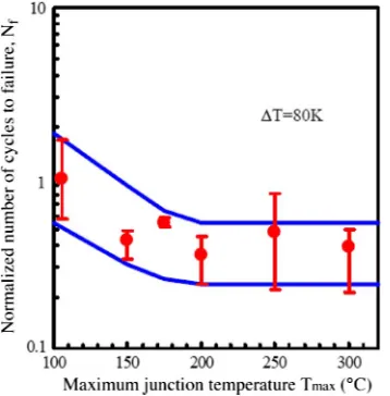
In [26], the effect of maximum temperature was investigated by varying it from 105 ◦C to 300◦C while keepingΔT at a constant 80 K. Although a decrease in lifetime was observed forTmaxvalues between 105◦C and 200◦C, no major change in fatigue characteristics of wire bonds was observed forTmax values between 200◦C and 300◦C (Fig. 4).
[image:4.594.332.526.315.495.2]Fig. 4. Relationship betweenNfand maximum junction temperature [26].
However, its influence on failure is yet to be captured meaning-fully by existing PoF models for wire bonds.
A number of disadvantages of the models discussed so far become apparent. These models generally focus on one mechanism as the cause of failure. This, we now recognize, is a rather simplistic view, because a broader wear-out mechanism such as wire bond liftoff can encompass a number of con-stituent mechanisms such as those which are diffusion driven, and whose interactions with fatigue can be complex under any given set of operation conditions. This also raises into question the use of accelerated testing, as there is a danger of these elements being overlooked or incorrectly represented. For example, if a fatigue-based wear-out mechanism, such as given by equations (1) and (2) is accelerated by temperature, then temperature-driven mechanisms, such as creep, which interact with fatigue are not accounted for, even though they are active under the acceleration conditions. Furthermore, because such models are material and mechanism specific, an enormous bank of life-testing data is needed. This is a huge snag, given that accelerated models are crucial to present-day assessment and qualification procedures.
In an attempt to address these issues, the authors put forward a damage-based prediction methodology in [35]. Since the observed grain coarsening and softening might be attributed to dislocation annihilation and a reversal of plastic strain [38], [39], it was concluded by the authors in [35] that “damage re-moval” and damage accumulation occur in tandem during ther-momechanical cycling, and that the seemingly anomalous trend in bond degradation observed could be due to a dominance of the former at high-enough temperatures. Their model predicted degradation rate β of the bond shear force by introducing a variableD1 to account for damage removal during exposure to elevated temperatures
β= D1
AΔT−M. (10)
[image:5.594.75.254.70.252.2]D1 represents the proportion of damage remaining after a single thermal cycle.AandM are numerical constants usually determined experimentally.
Fig. 5. Schematic graph of a wire bond foot.
Although this model innovatively attempts to take account of the aforementioned damage removal effects on the bond degradation rate, the Coffin–Manson expression still forms the basis of its calculation of accumulated damage. Moreover, since the derived expression for D1 is only valid for one particular temperature–time profile, this model cannot be readily extended to an arbitrary temperature–time profile.
Thus far, all of the models reviewed have been developed under the assumption that the bond wire is subjected to regular cyclic loading. In reality, however, power modules are usually subjected to irregular time-varying loads, either as a conse-quence of environmental changes or load cycling. Although the Rainflow counting method can be used to convert irregular time series into a sequence of cycles, this counting algorithm typically uses just the extreme points of the loads [40]. In [16] a probabilistic approach was employed to include the uncertainty of the temperature variation, but it just used a probability density function to statistically account for the temperature range history. In essence, cycle-based modeling methods are too simplistic and cannot readily describe the impact of time-at-temperature on the bond wear-out behavior.
IV. DAMAGE-BASEDCRACKPROPAGATIONMODEL IN TIME-DOMAINREPRESENTATION
Consequently, an altogether new approach to wire bond life prediction models is needed which can account for the com-bined effect of damage removal and accumulation processes, as well as be able to predict life of arbitrary mission profiles. In such an approach, cycle-dependent methodologies may be replaced with a time-domain representation. In a previous pub-lication [41], such a model has been presented in detail, and is summarized as follows.
A. Model Proposal
defined as a function of time and position through a differential equation which includes the effects of time- and temperature-dependent material properties.
Strain hardening and softening occur concurrently in bonding wire materials during temperature fluctuation [42]. Accordingly, the work hardening behavior of the material is represented by a damage accumulation term. Moreover, work hardening is influenced by temperature [43] and dynamic re-covery and recrystallization which take place during thermal cycling [44], [45], evidenced by softening and subgrain growth. These thermally activated, time-dependent processes are also taken into account in the model via a damage removal term.
Thus the incremental damage at any position along the bonding interface can be described by the following general equation:
δD(y, t) =f(ε)f(D)f(T)δT−α(D)α(T)δt. (11)
The position at the bonding interface is represented by y
as the distance from the origin. The first term on the right-hand side of (11) accounts for the accumulation of the damage that is determined by the existing damage in the material
D, the accumulated strain ε, and temperature T. The second term represents thermally activated damage removal processes dependent on the existing damageD, loading temperatureT
and the timetspent at this temperature.
f(ε)is a strain distribution function representing the strain concentration factor at any position along the bonding interface
f(ε) =G0
−√ x
LW|εp|
. (12)
The term √LW defines the approximate bond foot length scale (L and W are the bond foot length and width, respec-tively);G0is a damage coefficient andεpis the plastic strain;x
defines the position at the bonding interface with respect to the crack tip.
f(D)is a work hardening term describing the damage accu-mulation process
f(D) =1+αHDβH (13)
whereαH is the work hardening constant andβH is the work
hardening exponent.
f(T)is a temperature-dependent damage term defining the dependency of accumulated damage on the loading temperature assuming that multiplication and annihilation reach equilibrium at temperatureTeq
f(T) =
Teq
T
βT
(14)
whereβT is the temperature hardening exponent.
δT is represented by temperature-driven displacement strain
δεddue to the mismatched thermal expansion coefficients of the
two bonded materials, assuming that the two bonded materials had the same length at the equilibrium temperatureTeq
δεd= ΔCT E·δT = (αw−αc)·(T−Teq) (15)
αwandαc are the thermal expansion coefficients of the bond
wire and semiconductor chip, respectively.
α(D) represents the existing damage.
α(T) is the Arrhenius expression to reflect the effect of temperature on the damage annihilation rate.
α(T) =k2 exp
− Q
RT
(16)
Qis the activation energy;Ris the gas constant andk2 is an annealing coefficient.
The total interface damage(DT)at each time instant(t)can
be calculated by the integration of the damage for all the points along the interface from the crack tip by (12)
DT(t) = y=L
y=l
D(y, t)dy (17)
where L and l represents the original bond length and crack length, respectively. Crack lengthlcan be estimated by defining the crack growth rate as a function of total damage and the rate of change of total damage
dl
dt =f(DT) +g
dDT dt
. (18)
Furthermore, decrease in bond shear strength can be at-tributed to a reduction in the bonded area as a crack grows. Hence, shear force is commonly used to quantify bond degra-dation, and can be empirically obtained for a given loading condition. The magnitude of shear force Fs can therefore be
determined by the crack length l and the original bond foot lengthL
Fs=
L−l L
F0 (19)
where F0 is the initial shear force. The time to failure of the wire bonds can be estimated when the shear force reduces by certain percentage with respect to the initial value.
B. Some Simulation Results
1) Effect of Time-at-Temperature on Damage Development: One major advantage the proposed time-domain model has over cycle-based lifetime models is that it is able to more accu-rately reflect the temperature–time effects discussed previously. Moreover, these are represented in such a way that the model is not restricted to one material (e.g., aluminum). This is because the necessary work hardening and annealing parameters can be easily determined experimentally.
Fig. 6. (a) Temperature profile A and evolution of interface damage. (b) Temperature profile B and evolution of interface damage.
It can be seen that the damage develops at a different rate, and the saturation value of damage corresponding to profile B is smaller than that of profile A. This indicates that the model is able to demonstrate the effect of damage removal and time-at-temperature on the overall evolution of the damage.
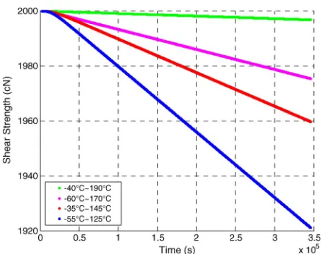
2) Simulation of Bond Shear Strength Degradation: Evo-lution of bond shear strength is simulated by operating the damage-based crack propagation model under the four tem-perature loading conditions to which the aluminum bonding samples were subjected in the thermal cycling described in [36]. The simulated shear strength degradation lines are demon-strated in Fig. 7 based on time unit (second). To obtain a comparison with the experimental data which is evaluated per cycle, the simulation results of the wear-out rate were converted into the unit of per cycle. They are listed in Table I. These early results show good agreement between the experimental data and simulation results, and indicate that the model can describe these high-temperature related phenomena correctly. However, further experimental validation is required, and further work to link the functionsfD(D),fT(T)andαT(T)with measurable
materials properties is still underway.
Fig. 7. Simulation of shear strength degradation of Al bonds under four temperature profiles.
TABLE I
COMPARISONS OF THESHEARSTRENGTHDEGRADATIONRATEBETWEEN
EXPERIMENTALDATA ANDSIMULATIONRESULTS
V. CONCLUSION
[image:7.594.307.544.314.408.2]REFERENCES
[1] M. Pecht, B. Tuchband, N. Vichare, and Q. J. Ying, “Prognostics and health monitoring of electronic,” inProc. Int. Conf. EuroSime, 2007, pp. 1–8.
[2] M. Pecht, A. Dasgupta, and P. Lall, “A failure prediction model for wire bonds,” inProc. ISHM, Baltimore, MD, Oct. 17–19, 1989, pp. 607–613. [3] C. A. Preussger, R. Blish, S. Huber, T. Dellin, and N. Lycoudes,
“Un-derstanding and developing knowledge-based qualifications of silicon de-vices,” Int. SEMATECH, Austin, TX, Technol. Transf. 04024492A-TR, Mar. 30, 2004.
[4] K. Upadhyayula and A. Dasgupta, “Physics-of-failure guidelines for ac-celerated qualification of electronic systems,”Qual. Reliab. Eng. Int., vol. 14, no. 6, pp. 433–447, Nov./Dec. 1998.
[5] M. J. Cushing, D. E. Mortin, T. J. Stadterman, and A. Malhotra, “Compar-ison of electronics-reliability assessment approaches,”IEEE Trans. Rel., vol. 42, no. 4, pp. 542–546, Dec. 1993.
[6] M. Pecht and A. Dasgupta, “Physics-of-failure: An approach to reliable product development,”J. Inst. Environ. Sci., vol. 38, no. 5, pp. 30–34, Sep./Oct. 1995.
[7] L. F. Coffin, Jr., “A study of the effects of cyclic thermal stresses on a ductile metal,”Trans. ASME, vol. 76, no. 6, pp. 931–950, 1954. [8] S. S. Manson, “Behaviour of materials under conditions of thermal stress,”
NACA, Washington, DC, Rep. No. 1170, 1954.
[9] H. L. L. Pang, T. L. Tan, J. F. Leonard, and Y. S. Chen, “Reliability assessment of a wirebond chip-on-board package subjected to accelerated thermal cycling loading,” inProc. IEEE/CPMT, 1997, pp. 93–97. [10] N. V. Chidambaram, “A numerical and experimental study of temperature
cycle wire bond failure,” inProc. 41st ECTE, 1991, pp. 877–882. [11] K. N. Meyyappan and P. Hansen, “Wire fatigue model for power
elec-tronic modules,” inProc. IMECE, Washington, DC, Nov. 15–21, 2003, pp. 257–265.
[12] S. Ramminger, N. Seliger, and G. Wachutka, “Reliability model for Al wire bonds subjected to heel crack failures,”Microelectron. Reliab., vol. 40, no. 8–10, pp. 1521–1525, Aug.–Oct. 2000.
[13] L. Merkle, T. Kaden, M. Sonner, A. Gademann, J. Turki, C. Dresbach, and M. Petzold, “Mechanical fatigue properties of heavy aluminum wire bonds for power applications,” inProc. IEEE 2nd Electron. Syst. Integr. Technol. Conf., Greenwich, U.K., 2008, pp. 1363–1368.
[14] G. Khatibi, M. Lederer, B. Weiss, T. Licht, J. Bernardi, and H. Dan-ninger, “Accelerated mechanical fatigue testing and lifetime of inter-connects in microelectronics,”Proc. Eng., vol. 2, no. 1, pp. 511–519, Apr. 2010.
[15] J. Bielen, J.-J. Gommans, and F. Theunis, “Prediction of high cycle fatigue in aluminium bond wires: A physics of failure approach combining exper-iments and multi-physics simulations,” inProc. 7th Int. Conf. EuroSime, Como, Italy, 2006, pp. 1–7.
[16] J. M. Hu and M. Pecht, “A probabilistic approach for predicting thermal fatigue life of wire bonding in microelectronics,”J. Electron. Packag., vol. 113, no. 3, pp. 275–285, Sep. 1991.
[17] M. Ciappa, “Selected failure mechanisms of modern power modules,”
Microelectron. Reliab., vol. 42, no. 4/5, pp. 653–667, Apr./May 2002. [18] J. Goehre, M. Schneider-Ramelow, U. Geißler, and K.-D. Lang, “Interface
degradation of Al heavy wire bonds on power semiconductors during ac-tive power cycling measured by the shear test,” inProc. CIPS, Nuremberg, Germany, Mar. 16–18, 2010, pp. 1–6.
[19] M. Ciappa and W. Fichtner, “Lifetime prediction of IGBT modules for traction applications,” inProc. IEEE 38th Annu. Int. Rel. Phys. Symp., San Jose, CA, 2000, pp. 210–216.
[20] J. Onuki, M. Koizumi, and M. Suwa, “Reliability of thick Al wire bonds in IGBT modules for traction motor drives,”IEEE Trans. Adv. Packag., vol. 23, no. 1, pp. 108–112, Feb. 2000.
[21] M. Ishiko, M. Usui, T. Ohuchi, and M. Shirai, “Design concept of wire-bonding reliability improvement by optimizing position in power de-vices,”Microelectron. J., vol. 37, no. 3, pp. 262–268, Mar. 2006. [22] M. Held, P. Jacob, G. Nicoletti, P. Scacco, and M. H. Poech, “Fast power
cycling test for IGBT modules in traction application,”Int. J. Electron., vol. 86, no. 10, pp. 1193–1204, Oct. 1999.
[23] U. Scheuermann and U. Hecht, “Power cycling lifetime of advanced power modules for different temperature swings,” inProc. PCIM, Nurem-berg, Germany, 2002, pp. 59–64.
[24] R. Amro and J. Lutz, “Power cycling with high temperature swing of dis-crete components based on different technologies,” inProc. IEEE PESC, Aachen, Germany, 2004, pp. 2593–2598.
[25] R. Amro, J. Lutz, J. Rudzki, R. Sitting, and M. Thoben, “Power cycling at high temperature swings of modules with low temperature joining technique,” inProc. 18th ISPSD, Naples, Italy, Jun. 4–8, 2006, pp. 1–4.
[26] T. Matsunaga and Y. Uegai, “Thermal fatigue life evaluation of aluminium wire bonds,” inProc. IEEE Electron. Syst. Integr. Technol. Conf., Dresden, Germany, 2006, pp. 726–731.
[27] A. T. Bryant, P. A. Mawby, P. R. Palmer, E. Santi, and J. L. Hudgins, “Exploration of power device reliability using compact device models and fast electrothermal simulation,”IEEE Trans. Ind. Appl., vol. 44, no. 3, pp. 894–903, May/Jun. 2008.
[28] W. C. Wu, M. Held, P. Jacob, P. Scacco, and A. Birolini, “Investiga-tion on the long term reliability of power IGBT modules,” in Proc. Int. Symp. Power Semicond. Devices ICs, Yokohama, Japan, 1995, pp. 443–448.
[29] M. Glavanovics, T. Detzel, and K. Weber, “Impact of thermal overload op-eration on wirebond and metallization reliability in smart power devices,” inProc. 34th Eur. Solid-State Device Res. Conf., 2004, pp. 273–276. [30] D. O. Harris, R. A. Sire, C. F. Popelar, M. F. Kanninen, D. L. Davidson,
L. B. Duncan, J. M. Kallis, D. W. Buechler, P. G. Backes, and F. Reizman, “Fracture mechanics life prediction for microscale components-with application to wire bonding,” in Proc. IEEE/IRPS, 1991, pp. 35–43.
[31] K. Sasaki and N. Iwasa, “Thermal and structural simulation techniques for estimating fatigue life of an IGBT module,” inProc. 20th Int. Symp. Power Semicond. Devices IC’s, Orlando, FL, May 18–22, 2008, pp. 181– 184.
[32] V. Mehrotra, J. He, M. S. Dadkhah, K. Rugg, and M. C. Shaw, “Wirebond reliability in IGBT-power modules: Application of high resolution strain and temperature mapping,” inProc. 11th ISPSD, 1999, pp. 113–116. [33] M. C. Shaw, D. B. Marshall, B. J. Dalgleish, M. S. Dadkhah, M. Y. He, and
A. G. Evans, “Fatigue crack growth and stress redistribution at interfaces,”
Acta Metall. Mater., vol. 42, no. 12, pp. 4091–4099, Dec. 1994. [34] Y. Celnikier, L. Benabou, L. Dupont, and G. Coquery,
“Investiga-tion of the heel crack mechanism in Al connec“Investiga-tions for power elec-tronics modules,” Microelectron. Reliab., vol. 51, no. 5, pp. 965–974, May 2011.
[35] P. A. Agyakwa, W. S. Loh, M. R. Corfield, E. Liotti, S. C. Hogg, and C. M. Johnson, “Anomalous reliability behaviour of 99.99% and 99.999% pure aluminium wire bonds under thermal cycling,” inProc. 41st IMAPS, Providence, RI, 2008.
[36] P. A. Agyakwa, M. R. Corfield, L. Yang, J. F. Li, V. M. F. Marques, and C. M. Johnson, “Microstructural evolution of ultrasonically bonded high purity Al wire during extended range thermal cycling,”Microelectron. Reliab., vol. 51, no. 2, pp. 406–415, Feb. 2011.
[37] Y. Yamada, Y. Takaku, Y. Yagi, I. Nakagawa, T. Atsumi, M. Shirai, and I. Ohnuma, “Reliability of wire-bonding and solder joint for high temper-ature operation of power semiconductor device,”Microelectron. Reliab., vol. 47, no. 12, pp. 2147–2151, Dec. 2007.
[38] N. Murdeshwar and J. E. Krzanowski, “A microstructural study of dis-location substructures formed in metal foil substrates during ultrasonic wire bonding,”Metall. Mater. Trans. A, vol. 28, no. 12, pp. 2663–2671, Dec. 1997.
[39] G. Konig and W. Blum, “Comparison between the cell structures produced in aluminium by cycling and by monotonic creep,”Acta Metall., vol. 28, no. 4, pp. 519–537, Apr. 1980.
[40] Standard Practices for Cycle Counting in Fatigue Analysis, ASTM E1049-85(2011)e1.
[41] L. Yang, P. A. Agyakwa, and C. M. Johnson, “A time-domain physics-of-failure model for the lifetime prediction of wire bond interconnects,” inProc. ESREF, Bordeaux, France, 2011, Microelectronics Reliability 51 (2011).
[42] C. Y. Yu, P. L. Sun, P. W. Kao, and C. P. Chang, “Evolution of microstruc-ture during annealing of a severely deformed aluminium,”Mater. Sci. Eng., vol. 366, no. 2, pp. 310–317, Feb. 15, 2004.
[43] G. Konig and W. Blum, “Comparison between the cell structures produced in aluminium by cycling and by monotonic creep,”Acta Metall., vol. 28, no. 4, pp. 519–537, Apr. 1980.
[44] C. E. Feltner and C. Laird, “Cyclic stress-strain response of F.C.C. metals and alloys—I: Phenomenological experiments,”Acta Metall., vol. 15, no. 10, pp. 1621–1632, Oct. 1967.
[45] C. E. Feltner and C. Laird, “Cyclic stress-strain response of F.C.C. metals and alloys—II: Dislocation structures and mechanisms,” Acta Metall., vol. 15, no. 10, pp. 1633–1653, Oct. 1967.
[46] Y. Nakanishi, T. Fujii, S. Onaka, and M. Kato, “Low-cycle fatigue of ultrafine-grained aluminum at low temperatures,”Mater. Trans., vol. 52, no. 5, pp. 890–894, May 2011.
Li Yang received the B.E. degree in applied electronic technology from Xi’an University of Technology, Xi’an, China, in 1996 and the M.Sc.(Distinction) in automation and control from Newcastle University, Newcastle upon Tyne, U.K., in 2008. She is currently working toward the Ph.D. degree at The University of Nottingham, Nottingham, U.K.
She was an electrical engineer with Northwest Institute of Electronic Equipment for eight years. Her research interests include reliability modeling and assessment and testing for integrated power electronic module and packaging.
Pearl A. Agyakwareceived the B.Sc. degree in ma-terials science from Brunel University, Middlesex, U.K., in 1999 and the Ph.D. degree in metallurgy from The University of Nottingham, Nottingham, U.K., in 2004.
She has held a number of university posts since then, including one with The University of Sheffield Advanced Manufacturing Research Centre with Boeing, South Yorkshire, U.K., managing applied research projects for the benefit of industrial partners within the aerospace sector. She is currently a Re-search Fellow with the Department of Electrical and Electronic Engineering, The University of Nottingham, within a multidisciplinary team of researchers studying various elements of power electronics packaging, where she focuses on the materials science aspects of interconnect reliability.
C. Mark Johnson (M’91) received the BA de-gree in engineering and the Ph.D. dede-gree in electri-cal engineering from the University of Cambridge, Cambridge, U.K., in 1986 and 1991 respectively.
![Fig. 2.Effect of increasing number of cycles on mean shear force [36].](https://thumb-us.123doks.com/thumbv2/123dok_us/8708371.382633/4.594.332.526.315.495/fig-effect-increasing-number-cycles-mean-shear-force.webp)