doi: 10.4236/jemaa.2009.13025 Published Online September 2009 (www.SciRP.org/journal/jemaa)
Optimal Power System Restoration and
Reconfiguration in Distribution Circuit
Using BFAM and BPSO
K. Sathish KUMAR, T. JAYABARATHI
School of Electrical Sciences, VIT, Vellore, Tamil Nadu, India. Email: k_sathishkr@sify.com
Received June 19th, 2009; revised July 30th, 2009; accepted August 7th, 2009.
ABSTRACT
This paper approaches the problem of restoring a faulted area in an electric power distribution system after locating and isolating the faulted block and reconfiguring the system. Through this paper we are going to explain the power system restoration technique using brute-force attack method (BFAM) and binary particle swarm optimization (BPSO). This is a technique based on the possible combination in mathematical analysis which is explained in the introduction. After isolating the fault, main concentration will be towards the reconfiguration of the restored system using BPSO. Here due to fault in the system near-by agent will be affected and become useless and will go in the non-working mode. Now in order to restore these near-by loads we will give a new connection called NO (Normally Open. Using these switch system will be restored with power availability. After restoration using the BFAM, the BPSO will be used in or-der to provide the stable configuration. The output of the BFAM will be used as input for the BPSO and then we will reconfigure our system in order to provide the stable configuration. The effectiveness of the proposed BFAM and BPSO is demonstrated by simulating tests in a proposed distribution network and verified the results using the Matlab and C programming.
Keywords: Brute-Force Attack Method, Power System Restoration and Particle Swarm Optimization
1. Introduction
The key elements of power system are its continuity and reliability. If these two elements are deviated from their normal condition then it may leads to the system in ab-normal conditions which may be either alert state or emergency state. Both shouldn’t be entertained in the system. If condition reaches to the extreme state then we may have to shut down our system, this leads to a heavy loss in terms of money and customer satisfaction. This is the area on which many real time researches are going on and still future can’t be predicted. So up to 99%, continu-ity of the system can be maintained but due to fault, 1% can’t be predicted. Hence the assurance to the customers that their system is 100% efficient cannot be given. In order to overcome this problem and for system recon-figuration we just go through a process called restoration. It is nothing but process of maintaining power balance after fault. The main aim of system restoration is to re-store as many as loads possible which are being affected by faulted nodes by considering available power without violating constraints of the system. Through this paper
we have implemented a technique for power system res-toration which uses the BFAM and finally reconfigure itself using the BPSO. First section of our paper includes the introduction and basic idea of the BFAM. In this sec-tion we will have an idea how we achieve our restorasec-tion process using this technique after a fault. The second section will give a real time analysis of restoration proc-ess using the BPSO using transmission and distribution parameters. In this section we take the output solution of the restoration in BPSO as input and final output is used to reconfigure the system. In the third section we com-pared the proposed BPSO using the BFAM. In section four, an attempt has been made to find a new method for restoration using BPSO and BFAM considering their advantages with each other.
2. Brute Force Attack Method
on the possible combination in mathematical analysis. For a three digit number we have possible thousand com-binations (000–999) and there is an only one solution by taking all the possible combination and arranging them we can get our required one solution. In the same way, in our power system if a node has fault then its near-by agents will make all the possible combination with the near-by node starting(1st) to end(nth) and then will go up to the last load and the best solution path out of these combination will be used for the restoration. Here we have compared the BFAM with the restoration using multi-agent technique [1–3]. Due to the fault in the load they are unable to receive the power. Hence our aim is to restore the faulted load considering the various factors like time, amount of power available to the feeder and system continuity. The constraints are
The system’s radial structure must be maintained during the analysis.
Restore maximum possible load within the out-of service area with the available feeder power.
The plan must not overload any equipment or system component with its rated value.
The numbers of switching operation should be minimum in order to save the power losses.
After reconfiguration the system should maintain its continuity and reliability.
3. Problem Formulation
In this section we will formulate a system so that we can perform an analysis on this system after a fault. We can represent any system with the nodes (N) formed by the network blocks and switches (S) which connects the two blocks that may be in opened or closed position. Feeder is one of the parameter of the system which supplies the power to the system and has the demand power and extra power. Hence for each load its required power must be known to us. Thus by calculating the demand of each node we will calculate the total demand of any feeder. Now after finding total demand of the feeder we can find the reserve capacity by subtracting the total demand of the load with from the total capacity of the system load is also a one of the important parameter of the system which consumes the power supplied by the generating part of the system. In addition, we are going to consider a three feeder system for simplicity. The real system is very large and we generalized this method for a large system also. Beside these parameters there is one more special connection between the loads of feeder one to the load of other feeder. This special connection is working in such a way that, connection is NO (normally open) condition when there is no fault in the system, but it will close as soon as there is a fault in the feeder. Now we analyse our system as a tree which have its sub-tree con-nected in a proper path. The advantage of tree
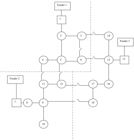
configura-tion is that it is efficient in order to maintain distribuconfigura-tion feeder continuity and radiality. Now in figure 1 the status of a 3 feeder network having 5 loads in each feeder is shown. In general the feeder will work normally and each feeder will provide the necessary amount of power to each load depending upon their requirement and some amount of power will always be there as in reserve mode. Now initially the switch D will be in NO (normally open) condition as there is no fault in the system. As soon as there is a fault in the system the whole of the system status of system will change.
4. Fault Analysis
avail-ability of the feeder. If all the feeders don’t have addi-tional power for the blocks then in that condition our blocks can’t be restored. After the separation of near-by agent from the faulted load the special switch D will come in to the network. In the above system the switch D will close for the load 3–5 & 6. Hence they will get re-quired amount of power from the near-by feeder and can restore themselves. Hence load 3 connects itself from load 14 of feeder 3 and it will be restored. Now feeder 3 is having zero additional units, load 4 and 5 will con-nected itself from the load 11 and 12 of feeder 2 and it can be restored. Now feeder 2 is having 0 buffer unit, finally the load 6 will not be restored as no feeder is hav-ing additional amount of units.
Now our algorithm maintains a list of solution, which is initially vacant and to which the solutions are added as they are found as the maximum number of solution in the list and it can be changed by the operator. In the list the best solution will be taken as the final conclusion for our fault analysis.
4.1 The Steps in the Algorithm
1) Identify the block in which the fault is occurred. 2) Open all switches connected to that block in order to isolate it. For each switch that is opened, a sub-tree is generated, which have to be restored, except for the switch that connects the faulted block to a block the feeder is still feeding normally (a block that is “before” the fault).
3) Based on step 2, make change in the bus connec-tivity matrix and from the load status array. Put zero in bus connection matrix for no connection between node and put zero for unfed node in load status array. If there is a connection between two unfed node(load[i,j]=1) change it by loop Switch(load[i,j]=2).
4) Create a list of the blocks still being fed and con-taining at this moment only the blocks the substation is still feeding, if any.
5) Check if there is a loop switch between a fed block and an unfed one. (Possible connections are represented as 2 in bus-connectivity matrix).
6) The unfed block which is only connected to faulted block (node or load) cannot be restored.
7) If there is a loop switch between fed and unfed block, check the feeder at which the fed block is getting power.
8) If that feeder has additional power for unfed block, connect the fed and unfed node and make necessary changes in the load connectivity matrix and load status array.
9) Now move to next unfed block and repeat from step 4.
10) After checking the each unfed block, repeat again from step 4 for ‘n’ times where n=no of fault node (block) from starting.
11) Check the load status and which node the value to load status is zero and that cannot be restored.
5. Fitness Function
To make the stability and reliability of the distribution it is very important to keep the load balancing via feeder reconfiguration so that network could be enhanced. The objective of this optimization problem can be expressed by the minimization of the load balancing index (LBI) as in [5]:
LBI= 2
1 | | ( ) N i i R i i I L I
whereN: Total number of branches in the system after restora-tion,
Li: Length of branch i,
Ii: Complex current flow in branch i,
R i
I : Current rating (ampacity) of bus i.
The LBI value should be minimum in-order to get the best solution by adjusting the switch position. According to the switch operation the complex current is flowing through sectionalized switches in the simplified model [6]. The reconfiguration problem cannot be solved by the traditional methods because of the non linearity of the system after the fault.
6. PSO
The PSO algorithm was first proposed by Eberhart and Kennedy [7]. In PSO method, each individual is treated as particle in the H-dimensional search space. Each indi-vidual in the search space has some velocity which is dynamically adjusted according to its own and its neighbour’s the moving experience.
6.1 BPSO
Feeder 1
[image:4.595.85.517.79.533.2]1
Figure 1. System working in normal condition when there is no fault in the system
trajectories of Vih are changed in the probability that a coordinate will take on zero or one value or in between them [8]. The moving velocity is defined in terms of changes of probability that a bit will be in one state or the other depending on the trajectory of Vih. Thus a particle moves in a state space restricted to 0 and 1 on each di-mension, where Vih represents the probability of bit Xih taking the value 1. In other words, if Vih =0.45, then there is 45% chance that Xih will be 1, and 55% chance that Xih will be 0. With this definition, pih and xih can take inte-gers 0 or 1, and vih, since it is probability and it must lie within the interval [0, 1]. Hence for the proper
explana-tion we can determine the funcexplana-tion of this probability as shown below-
For h=1: H
1 1
( ) 2 2 ( );
ih ih
ih ih gh ih
V w v c rand
p x c rand p x
If (rand S v( ))ih then xih=1
else xih=0 (3)
end end S(x) = 1 1ex
where S(x) sigmoid limiting transformation. 4
3
5 2
6
14
7 8 9
11
10
12
13 15
18
17 16
Feeder 2
1
4
3
5 2
6
7 8 9
11
10
12
13 15
14
18
17 16
Feeder 2
Feeder 1
[image:5.595.83.513.81.459.2]Feeder 3
Figure 2. System after restoration with the help of near-by feeder when fault is there in block 2
[image:5.595.113.483.484.699.2]While applying the BPSO method there are some con-straints that we have to follow in order to maintain the continuity and radiality of the system.
Each feeder should be in active state in the whole system.
To maintain the radial structure of the system at least one branch from one feeder to another must be in open state otherwise the radiality of the system will be lost. The Potential limit for buses should be between minimum and maximum value. Beside this the operating conditions of the tie-switches will be also kept in mind [9]:
In the system at least one tie switch will be in closed position and all other in open position. The power flow should take place in load side end it should not flow in the feeder side.
6.1.1 Algorithm [10]
1) Set the population size (n), maximal iteration number and stop criterion.
2) Randomly select n feasible solutions of x, compute p for each x, pg is minimum in all pi, and the initial values of vi is zero.
3) Using (2), calculate vi for particle i. 4) Use (7), to update i.
5) Calculate the feeder load balancing index.
6) If the fitness value of particle i is better than the pre-vious pi, then set it to pi. If the best p is better than pg, then set it to pg.
7) If stop criterion is satisfied, pg is optimal solution, otherwise, go to step 3.
Now from the BFAM we are restoring our system by taking the best possible solution. For this system the ini-tial status and parameter of this system will be known to us. Now we will form the bus connectivity matrix for our system and for any fault in the system we will get a dif-ferent load connectivity matrix after the fault analysis corresponding to the load status and finally our system will give required solution for the proper restoration. The output of the fault analysis which will be stored in a variable will be the input of BPSO. Now corresponding to this BPSO we will get a final best solution which will be used for reconfiguration of the system. In this solution we keep the nearby switch of faulted load have to always at off state by proper logical AND operation. After this we will get our final solution and implement the same procedure for the reconfiguration.
7. Result Analysis
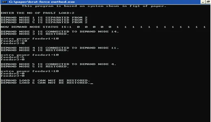
In the Figure 1 given in the last suppose fault is there in the load 2 than results for the restoration in the c pro-gramming will be-Enter the no of fault load=2
Demand node 1 is separated from 2 Demand node 3 is separated from 2
Demand node 5 is separated from 2
Demand node status is: - 1 0 0 0 0 0 1 1 1 1 1 1 1 1 1 1 1 1 Demand node 3 is connected to demand node 14, De-mand node 3 is restored.
Extra power Feeder1=10, Feeder2=10, Feeder3=0, Demand node 4 is connected to demand node 11, De-mand node 4 is restored. Extra power Feeder1=10
Feeder2=5, Feeder3=0 Demand node 5 is connected to demand node 4, Demand node 5 is restored. Extra power Feeder1=10, Feeder2=0, Feeder3=0
Demand node 6 cannot be restored
Demand node 2 cannot be restored (Figure 3)
8. Conclusions
Through this paper an attempt has been made to restore the faulted area in the power system and finally reconfig-ured the system in the stable state. The above process can be implemented in a real time network and can be used for the restoration through BFAM and reconfiguration through BPSO. Also we perform the fault analysis in a real time network and simulated the results in the MATLAB and C programming. We have implemented the BFAM to get the priority based solution. We find that the results found from the analysis are matching with the actual data. Hence the above method can be used to per-form the analysis of fault and to restore, reconfigure the system in a real network. The restored network is shown in the Figure 2 and the prospective analysis is given in the result analysis (7) and the proof in C is shown in the Figure 3. But the conventional methods are limited only for less number of loads.
REFERENCES
[1] J. A. Momoh, and J. L. Feng, “A multi-agent-based resto-ration approach for NAVY ship power system,” IEEE Center for Energy Systems and Control (CESaC) De-partment of ECE, Howard University, Washington DC, 2009
[2] T. Sakaguchi and K. Matsumoto, “Development of a knowledge based system for power system restoration,” IEEE Trans. Power App. Syst., Vol. PAS–102, pp. 320– 329, Feb. 1983
[3] K. Manjunath and M. R. Mohan, “A new hybrid multi-o- bjective quick service restoration technique for electric power distribution systems,” Science Direct, Electrical Power and Energy Systems, Vol. 29, pp. 51–64, 2007. [4] M. P. Papadopoulos, G. J. Peponis, N. G. Boulaxis, and N.
X. Drossoss, “Heuristic methods for the optimisation of MV distribution networks operation and planning,” Elec-tricity Distribution Part I. Contributions. 14th Interna-tional Conference and Exhibition on (IEE Conf Publ. No. 438), Vol. 6, pp. 9/1 –9/5, 2–5 June, 1997.
[5] J. Liu, P. X. Bi, Y. Q. Zhang, X. M. Wu, “Power flow analysis on simplified feeder modelling”.
[7] J. Kennedy and R. C. Eberhart, “A discrete binary version of the particle swarm algorithm,” Systems, Man, Cyber-natics, IEEE International Conference on Computational Cybernetics and Simulation, Vol. 5, pp. 4104–4108, 12– 15 Oct. 1997.
[8] A. Augugliaro, L. Dusonchet, M. G. Ippolito, and E. R. Sanseverino, “Minimum losses reconfiguration of MV distribution networks through local control of tie- switches,” IEEE Transactions on Power Delivery, Vol. 18, No. 3, pp. 762–771, July 2003.
[9] X. L. Jin, J. G. Zhao, Y. Sun, K. J. Li, and B. Q. Zhang, “Distribution network reconfiguration for load balancing using binary particle swarm optimization,” International Conference on Power System Technology-POWER- CON’04, Singapore, 21–24 Nov., 2004.