Learning manipulative skills using an artificial intelligence
approach.
CHMIELARCZYK, Pawel.
Available from Sheffield Hallam University Research Archive (SHURA) at:
http://shura.shu.ac.uk/19462/
This document is the author deposited version. You are advised to consult the
publisher's version if you wish to cite from it.
Published version
CHMIELARCZYK, Pawel. (2006). Learning manipulative skills using an artificial
intelligence approach. Doctoral, Sheffield Hallam University (United Kingdom)..
Copyright and re-use policy
/“vuoo'uo o c J iu it; o n y ^csm fjut*
S h effield 3 1 1W B
1 0 1 8 5 9 9 0 3 7
Return to Learning Centre of issue
Fines are charged at 50p per hour
ProQuest Number: 10694343
All rights reserved
INFORMATION TO ALL USERS
The qu ality of this repro d u ctio n is d e p e n d e n t upon the q u ality of the copy subm itted.
In the unlikely e v e n t that the a u th o r did not send a c o m p le te m anuscript and there are missing pages, these will be note d . Also, if m aterial had to be rem oved,
a n o te will in d ica te the deletion.
uest
ProQuest 10694343
Published by ProQuest LLC(2017). C op yrig ht of the Dissertation is held by the Author.
All rights reserved.
This work is protected against unauthorized copying under Title 17, United States C o d e M icroform Edition © ProQuest LLC.
ProQuest LLC.
789 East Eisenhower Parkway P.O. Box 1346
Learning manipulative skills using an Artificial Intelligence approach
Paw el C h m ielarczyk
A thesis submitted in partial fulfilment of the requirements o f
Sheffield Hallam University
for the degree o f Doctor o f Philosophy
Abstract
The aim o f this research was to design a non-linear controller based on an Artificial Neu
ral Network and Reinforcement Learning algorithms implementation, which is able to
perform an intelligent robotic assembly o f mechanical components.
Different information was applied and combined to develop a fully unsupervised, in
telligent controller. In the author’s design no class labelling or geometry feature pre
training takes place. Only force and torque signals together with the direction o f insertion
were supplied to the controller.
A unique sandwich structure o f the intelligent controller was proposed. It featured
two major layers, a State Recognition module where the detection and localisation o f the
contact points were performed, and the Decision Making subsystem where the decision
about the next action took place.
All the algorithms were implemented and tested on simulated data before being ap
plied to the real-life peg-in-hole insertion. The results are presented in the form o f graphs
and tables.
Evaluation o f the environmental uncertainty was accomplished. The signal from the
force and torque sensor was acquired under controlled conditions. All the data was col
lected to establish the area and level o f uncertainty (e.g. signal errors) the artificial con
troller would need to learn to cope with and compensate for.
The empirical part o f the thesis includes the investigation into the effects o f different
learning methods applied on the same geometry. The influence o f action-selection meth
ods on AI agent performance was analysed. The proposed controller was applied to a set
o f real life peg-and-hole experiments. Both circular and square peg geometries were used,
and insertions into chamfered and non-chamfered holes were performed. Materials with
different friction factors were used for mating parts.
Fast and stable knowledge acquisition was clearly present in all the cases investigated.
A significant reduction in contact force value during the initial stage o f the learning pro
cess was recorded. The force was usually reduced to one tenth o f the initial value. Some
fluctuations were recorded but when the cylindrical peg was considered the value o f con
Contents
List of Tables v
List of Figures vi
Acknowledgements x
List of abbreviations xi
List of symbols xii
Glossary of terms xiii
1 Introduction 1
1.1 Aims and objectives... 5
1.2 Original c o n trib u tio n ... 6
1.3 Thesis s tru c tu re ... 7
2 Intelligent motion control 9 2.1 Admittance m a p p i n g ... 9
2.2 Nonlinear compliance control with A N N s ... 11
2.3 Learning contact states with A N N s ... 15
2.4 Admittance mapping with Reinforcement L e a r n in g ... 17
2.5 D iscussion... 22
3 System design 25 3.1 Experimental s e t u p ... 25
3.2 The r o b o t ... 26
3.2.1 Robotic a r m ... 26
3.2.2 Control u n i t ... 29
3.3.1 Physical link - R S -2 3 2 C ... 32
3.3.2 Link Control - DDCMP ... 33
3.3.3 CRT terminal mode c o n n e c tio n ... 34
3.4 The sen sor... 35
3.4.1 JR3 sensor driver d e s ig n ... 36
3.5 Experimental s p e c im e n s ... 38
3.6 D iscussion... 39
4 Methodology 42 4.1 Controller arch itectu re... 42
4.1.1 The information flow within the controller... 44
4.2 The learning agent ... 44
4.2.1 Reinforcement learning... 45
4.2.2 Temporal-Difference m e th o d s ... 51
4.3 State domain clustering m odule... 56
4.3.1 Markovian S t a t e ... 56
4.3.2 State classification using Artificial Neural N e tw o r k s ... 57
4.4 Software implementation and data structures... 63
4.5 Algorithms s im u la tio n ... 65
4.5.1 Learning Agent evaluation... 66
4.5.2 State classification method evalu ation ... 78
4.6 D iscussion... 83
5 Experimental Methodology 88 5.1 Environment evaluation... 88
5.1.1 Sensor accuracy ... 89
5.1.2 Robot positional a c c u r a c y ... 91
5.2 Plan o f peg-in-hole ex p erim en ts... 93
5.2.1 Initial exp erim en ts... 93
5.2.2 SARSA and q-leaming on-line performance evaluation... 94
5.2.3 Different peg geometries a n a ly s is ... 94
5.2.4 Friction a n a ly s is ... 95
5.2.5 Nonlinear case analysis... 95
6 Results analysis 100
6.1 Initial experiments ...100
6.2 Chamfered, circular peg-in-hole i n s e r t i o n ... 104
6.2.1 Aluminium c o m p o n e n ts ... 105
6.2.2 Rubber peg t e s t ...113
6.3 Chamfer-less circular peg-in-hole insertion p ro b le m ... 117
6.4 Square peg a n a ly s is ... 121
6.5 D iscussion... 125
7 Conclusions and future work 133 7.1 Work d o n e ...133
7.2 Results summary and final conclusions... 135
7.3 Original c o n trib u tio n ... 138
7.4 Future w o r k ... 139
References 142 A Simulation results 147 A .l Action selection policy evaluation (q-leam ing)...147
A.2 State classification method e v a lu a tio n ...149
B Experimental results 159 B .l Environment evalu atio n ...159
B.1.1 Sensor accuracy ...159
B.2 Experimental results ...166
B.2.1 Circular chamfer-less hole - additional results... 166
B.2.2 Softmax and e-greedy comparison data...169
B.2.3 Q-leaming agent with e-greedy policy applied on chamfer-less peg-in-hole p r o b l e m ... 169
B.2.4 Complete raw data from square peg-in-hole insertion...172
C Rotations in TOOL Coordinate System 174 D ART2 algorithm 177 E Software description 179 E .l Floppy drive em u lato r...179
List of Tables
3.1 Puma 562 arm specification (after robot manual [40])... 28
3.2 Puma 562 control unit specification (after robot manual [40])... 29
3.3 Communication layers (after robot manual [40])... 32
3.4 Experimental specimens... 38
4.1 Learnt policies for different action-selection methods... 70
4.2 Learnt policies for SARSA and q-leaming methods... 77
4.3 Classification stability o f ART2 algorithm (p = 0.95)... 81
5.1 Robot incremental motion accuracy measurements for X axis... 92
5.2 Robot incremental motion accuracy measurements for Y axis... 92
5.3 Robot incremental motion accuracy measurements for Z axis... 92
A .l Leamt policies for different action-selection methods...148
A.2 Classification stability o f ART2 algorithm (p = 0.9)... 149
A.3 Classification stability o f ART2 algorithm (p = 0.91)...150
A.4 Classification stability o f ART2 algorithm (p = 0.92)... 151
A.5 Classification stability o f ART2 algorithm (p = 0.93)... 152
A.6 Classification stability o f ART2 algorithm (p = 0.94)... 153
A.7 Classification stability o f ART2 algorithm (p = 0.95)... 154
A.8 Classification stability o f ART2 algorithm (p = 0.96)... 155
A.9 Classification stability o f ART2 algorithm (p = 0.97)... 156
A. 10 Classification stability o f ART2 algorithm (p = 0.98)... 157
A .l 1 Classification stability o f ART2 algorithm (p = 0.99)... 158
List of Figures
1.1 Orders placed for industrial robots by region [38,39]... 2
2.1 Box palletizing task (after Asada [1])... 10
2.2 Contact states between peg and hole (after Asada [1,2])... 10
2.3 ANN structure for 2D chamfer-less insertion problem (after Asada [1]). . 12
2.4 Controller structure (after Lopez-Juarez [31])... 14
2.5 Contact states between peg and hole (after Cervera et al [13])... 15
2.6 Activation patterns for the three contact states case (after Cervera et al [13]). 16 2.7 Ball-aligning task (after Yang and Asada [46])... 18
2.8 Controller architecture (after Cervera and del Pobil [12])... 20
2.9 Learning agent architecture (after Brignone [4])... 21
3.1 Experimental setup... 26
3.2 Schema o f Puma 562 robotic arm... 27
3.3 DDCMP frame types used by VALII... 34
3.4 Software design... 40
4.1 A l controller architecture... 44
4.2 Reinforcement learning principle... 46
4.3 e-greedy action-selection method... 49
4.4 Gibbs distribution for simulated action values... 51
4.5 One step Q-leam algorithm flowchart... 53
4.6 SARSA algorithm flowchart... 55
4.7 Basic Processing Element... 58
4.8 ANN’s taxonomy (after Huang and Zhang [25])... 59
4.9 Implemented ART2 architecture (after Ferrman and Skapura [16])... 61
4.10 Data structure implementation for ART2 Neural Network... 64
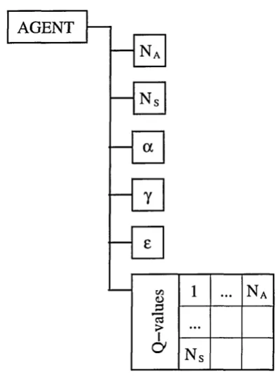
4.11 Data structure implementation for reinforcement learning agent... 65
4.13 The set of states the agent can experience during each play... 67
4.14 e-greedy policy evaluation using SARSA algorithm... 68
4.15 Softmax policy evaluation using SARSA algorithm... 69
4.16 Cliff walk environment (after Sutton and Barto [36])... 71
4.17 The on-line performance o f SARSA m eth o d ... 73
4.18 The number o f the agent’s failures using SARSA algorithm... 74
4.19 The on-line performance o f q-leaming method... 75
4.20 Number o f the agent’s failures using q-leaming algorithm... 76
4.21 Comparison o f q-leaming and SARSA algorithms on-line performances. . 78
4.22 The vigilance parameter against the number o f generated classes... 80
4.23 State classification using ART2 histogram... 82
5.1 Force results for 5N load applied on the sensor (uncorrelated signals). . . 90
5.2 Torque results for 5N load applied on the sensor (uncorrelated sig n als).. . 91
6.1 On-line performance o f the controller during the initial tests...101
6.2 Number o f failed insertions throughout the experiment... 102
6.3 Force value throughout the experiment...103
6.4 Peg and hole model used during the experiments... 104
6.5 Performance o f q-leaming algorithm - e-greedy action-selection policy. . 106
6.6 Performance o f q-leaming algorithm - Softmax distribution policy...107
6.7 Softmax and e-greedy policy during first 400 episodes... 107
6.8 Force data from the peg-in-hole experiment - Softmax policy...108
6.9 Torque data from peg-in-hole experiment...109
6.10 Number o f failed insertions during peg-in-hole experiment...110
6.11 Cumulative rewards data acquired using SARSA algorithm...I l l 6.12 Force data acquired using SARSA algorithm...112
6.13 Torque data acquired using SARSA algorithm... 112
6.14 Number o f the agent’s failures using SARSA algorithm... 113
6.15 Peg and hole model used during the experiments... 114
6.16 On-line performance data from peg-in-hole experiment...115
6.17 Force data from peg-in-hole experiment... 115
6.18 Torque data from peg-in-hole experiment...116
6.19 Number o f failed insertions per 10 episodes - rubber peg applied... 116
6.20 Peg and hole model used during the experiments... 117
6.22 Force data from peg-in-hole experiment...119
6.23 Torque data from peg-in-hole experiment... 119
6.24 Number o f failed insertions (per 10 episodes)... 120
6.25 Peg and hole model used during the experiments...121
6.26 On-line performance data from peg-in-hole experiment... 122
6.27 Force data from peg-in-hole experiment...123
6.28 Torque data from peg-in-hole experiment... 124
6.29 Number o f failed insertions (per 10 episodes)... 125
A. 1 e-greedy policy evaluation using q-leaming algorithm... 147
A.2 Softmax policy evaluation using q-leaming algorithm... 148
A.3 State classification using ART2 (p=0.9)... 149
A.4 State classification using ART2 (p=0.91)... 150
A.5 State classification using ART2 (p=0.92)... 151
A.6 State classification using ART2 (p=0.93)... 152
A . l State classification using ART2 (p=0.94)... 153
A.8 State classification using ART2 (p=0.95)... 154
A.9 State classification using ART2 (p=0.96)... 155
A. 10 State classification using ART2 (p=0.97)... 156
A .l 1 State classification using ART2 (p=0.98)... 157
A. 12 State classification using ART2 (p=0.99)... 158
B. 1 Force reading on X-axis - unfiltered data...160
B.2 Force reading on Y-axis - unfiltered data... 160
B.3 Force reading on Z-axis - unfiltered data... 161
B.4 Force reading on X-axis - 31 Hz filter applied... 161
B.5 Force reading on Y-axis - 3 1Hz filter applied...162
B.6 Force reading on Z-axis - 3 1Hz filter applied...162
B.7 Torque reading on X-axis - unfiltered data... 163
B.8 Torque reading on Y-axis - unfiltered data...163
B.9 Torque reading on Z-axis - unfiltered data...164
B. 10 Torque reading on X-axis - 31 Hz filter applied...164
B. 11 Torque reading on Y-axis - 31 Hz filter applied...165
B. 12 Torque reading on Z-axis - 31 Hz filter applied... 165
B. 13 Force data - chamfered hole, q-leaming with e-greedy applied... 167
B.15 Number o f failed insertions (per 10 episodes)... 168
B.16 Softmax and e-greedy policy during first 400 episodes... 169
B.17 On-line performance data from the experiment... 170
B.18 Force data from peg-in-hole experiment...170
B. 19 Torque data from peg-in-hole experiment...171
B.20 Number o f failed insertions (per 10 episodes)... 171
B.21 On-line performance data from the experiment... 172
B.22 Force data from peg-in-hole experiment...172
B.23 Torque data from peg-in-hole experiment... 173
Acknowledgements
I would like to thank all those who helped me with this study.
Firstly, I extend my thanks to Dr Martin Howarth for providing the opportunity o f
carrying out this study, and for his encouragement and advise throughout. Special thanks
to Richard Wainwright for his steadfast assistance, especially during robot breakdowns.
Thanks also to my friend Glenys Rogerson for her patience and endurance in guiding me
through the nuances o f the English Language.
Finally I am grateful to my parents and friends for their continuous support throughout
List of abbreviations
The abbreviations are explained in the thesis at the point o f their first reference. However
they reproduced here for the benefit o f the reader.
Al Artificial Intelligence
ANN Artificial Neural Networks
ANSI American National Standards Institute
ART Adaptive Resonance Theory
CAD Computer Aided Design
CIM Computer Integrated Manufacturing
CPU Central Processing Unit
CRC Cyclic Redundancy Check
CRT Cathode Ray Tube
DDCMP Digital Data Communications Message Protocol
DOF Degree O f Freedom
ES Expert Systems
FL Fuzzy Logic
FMC Flexible Manufacturing Cell
F/T Force and Torque
GNU Gnu’s Not Unix
I/O Input - Output
ISO International Standards Organisation
LKM Loadable Kernel Modules
LTM Long Term Memory
MLP Multi Layer Perceptron
PKB Primitive Knowledge Base
POSIX Portable Operating System Interface for uniX
PUMA Programmable Universal Machine for Assembly
RAM Random Access Memory
RL Reinforcement Learning
SCARA Selective Compliant Assembly Robot Arm
SCS Supervisory Computer System
SOM Self Organising Map
SRV Stochastic Reinforcement Value
STM Short Term Memory
TD Temporal Difference
UNECE United Nations Economic Commission for Europe
List of symbols
The symbols are explained in the thesis at the point of their first reference. However they
reproduced here for the benefit o f the reader.
/ , F force vector
m, M torque vector
V linear velocity vector
UJ angular velocity
a RL learning ratio
7 RL discount factor
e probability o f exploratory action
P exploration bias
P Gibbs distribution ratio
P ART2 vigilance parameter
Q
transition function, mapping each state-action pair to a successor staten episode number
a set of actions an agent can perform
s set o f states an agent can experience
r reward from environment
t discrete time step
P'n activation patterns o f SOM
F I, F2 ART2 main layers
linear movement correction
69x, 56y, 56z rotational movement correction
0 , A, T angles o f robot’s TOOL coordinate system orientation
Glossary of terms
In this section a brief glossary o f domain specific terms is presented.
Artificial Neural Networks - a type o f massively parallel computing architectures based
on brain-like information encoding and processing models and, as such, they can
exhibit brain-like behaviours such as: learning, association, categorisation, gener
alisation, feature extraction, pattern recognition or optimisation.
Adaptive Resonance Theory - a type of ANN where the information in the form o f pro
cessing element outputs reverberate back and forth between layers. If the proper
patterns develop, a stable oscillation occurs. This is the neural-network equivalent
of resonance. Only during this stage can learning take place
Reinforcement learning - a goal oriented method o f knowledge acquisition where the
decision making process is based on value functions not on the immediate reward.
Temporal-Difference - learning algorithms to make long-term predictions about dynamic
systems.
Q-learning - an off-policy, Temporal-Difference learning method. The action-value func
tion Q directly approximates the optimal action-value function Q*, independent
o f the policy being followed.
SARSA - an on-policy, Temporal-Difference algorithm. Similarly to q-leaming SARSA
gathers knowledge from the state-action pairs transitions but it leams the policy
directly.
Value functions - a function which maps the actions (or state-action pairs) onto the re
sponse from the environment (the reward).
Reward - a primary feedback signal which provides the immediate response o f the envi
ronment.
Chapter 1
Introduction
Manufacturing could be described as a set o f operations and activities performed in order
to make a final product. It involves a product design, planning, production, assembly,
inspection and marketing.
Computers have been used in the manufacturing process for many years. It started in
the late 1960’s when they were applied to direct control o f groups o f machine tools [25].
Later the concept o f the Flexible Manufacturing Cell (FMC) was introduced. The FMC
defines a group o f semi-independent workstations linked by the material handling system.
This design allows a production o f a variety o f different items automatically. The increase
in computational speed o f modem CPUs caused a rapid advancement in development o f
Computer Integrated Manufacturing (CIM) systems. This approach allows a fast and
integrated flow o f manufacturing activities. The process o f making a part has become
fully automated which has contributed to improvement in quality and efficiency.
There has been a significant technological advancement since the introduction o f the
first commercial robot for automated assembly in the 1970s. The modem manipula
tors are faster, more reliable, and cost effective. High performance and a considerable
drop in prices has contributed to a significant increase in industrial application o f robots.
According to the United Nations Economic Commission for Europe (UNECE) report,
year 2001 was a record year for robotic investments in Europe [38]. Currently there are
is quickly increasing (see Figure 1.1).
The industrial robots have been successfully applied at almost every stage o f the man
ufacturing process. Tidd in his paper [37] classifies the industrial robots according to their
application into three major groups:
• handling robots - holding the components, loading or unloading the machines,
working in hazardous environments (e.g. nuclear industry),
• process robots - including painting, deburring, grinding, polishing, spot and arc
welding robots,
• assembly robots - involving an assembly o f the final component.
180
170 North America — 1— Europa —
Asia ...* -W orld total b
160
150
C/2
S 140 3
<4
-2 130 <D X
£
|
120110 100
1996 1997 1998 1999 2000 2001 2002 2003
Y ear
Figure 1.1: Orders placed for industrial robots by region [38,39].
Assembly operations are amongst the most common and complicated in the manufac
turing process. It usually requires an accurate motion control guided by a vision system
since the miniaturisation and complexity o f modem components make them impossible
to be assembled by a human (e.g. electronics industry). With the introduction o f CIM the
[image:19.616.125.479.270.523.2]The early applications o f robots in automated assembly techniques have relied on
passive accommodation methods, simple sensing systems and the manipulator’s program
ming language. These approaches show many restrictions that make them unable to deal
with a complex geometry o f the components. The advantage o f a passive system lies in
its stability while interacting with the environment during an assembly task.
In a typical force guided assembly task, the robot’s trajectory corrections are calcu
lated and applied, according to predefined control laws. The more sophisticated force
control methods involve modification o f trajectory based on continuous force feedback
from the system and a task description. Several methods of force control were researched.
Amongst them:
• damping control [27,41], where the sensed forces cause velocity modification,
• stiffness control [43], where the force is calculated from actual and desired arm
positions,
• impedance control [8,14,23], combination o f two methods above, the dynamic
relation between force error and position error is controlled,
• hybrid (position/force) control [32,41,45], in this method the force is controlled in
certain directions and position control is applied in the complementary directions
o f the end effector’s axes
Recently a new way o f programming has been proposed. The intelligent control em
braces substantially different techniques that include application o f knowledge based Ex
pert Systems (ES), Artificial Neural Networks (ANN), Fuzzy Logic (FL) or Reinforce
ment Learning (RL) algorithms. All these algorithms are different in principles and based
on different theories but their applications share similar methodology: an attempt to create
an effective mapping from sensory state space to the action domain.
The use o f adaptive and learning capabilities in the assembly process simplifies the
implementation and improves the reliability o f these systems. The main advantage o f
available for the solution. This has a tremendous impact on dealing with complex parts
geometry or noisy sensory signals during the assembly process as well as the development
o f automatic error recovery methods.
In a complex environment, hard coding o f every possible state-action mapping would
result in much larger source code than in the case o f self adapting methods application.
In some tasks, with an infinite number o f states, it is virtually impossible to implement
the relationships using traditional methods. With the ability o f ANNs to generalise, the
complex 3-dimensional state space could be clustered and classified.
The unsupervised neural and reinforcement learning controllers show the ability to
self-improve by using the experience gained from the previous tasks. This simplifies
tremendously the tedious task o f robot programming, and enables the controllers to learn
the best action for a given state without any supervisory influence.
The unsupervised, self-organising algorithms have revolutionised the modern intelli
gent assembly methods and are state o f the art in robot force control.
Early research work by Whitney [41,42] and Simunovic [35] concluded that most
common assembly operations could be modelled as simple peg-in-hole insertions. This
represents a large number o f part mating operations carried out in industry. Whitney
[42] defined 4 stages during peg-in-hole assembly operation. He also defines the failures
associated with insertions namely: jamming and wedging o f the peg.
The peg-in-hole model, its dynamics, and acting forces have been widely studied by
researchers [1,6,13,18,24,31].
The most successful industry-orientated approach was an application o f Remote Cen
tre Compliance (RCC) techniques. The passive compliance devise, proposed by Whitney
et al [44], consist o f springs and dampers to reduce the end effector stiffness. During
the assembly, the passive component o f the robot’s wrist deflects under the contact forces
correcting the misalignment o f mating parts.
Many assembly operations involve insertions o f the components with tolerances much
finer than the resolution and accuracy o f most available robots. This leads to the need
compliance problems associated with those operations. Simons et al [34] pioneered the
research and defined the need for learning and adaptivity in robotic assembly.
1.1 Aims and objectives
There are many areas where performance o f intelligent controller could be improved.
Most recent research has been focused on increasing the Al controller’s learning speed.
The research presented in this thesis aimed at the design, implementation and test o f the
unsupervised, intelligent system being able to perform a robotic assembly o f mechanical
components.
The main aims of this research include:
• Investigation o f the different information sources and their employment in the peg-
in-hole insertion problem. Amongst these, one source is sensory (signal from force
and torque sensor) and descriptive (geometry o f parts and coded task description
and assembly direction).
• Investigation o f automatic state recognition and clustering. This involves the analy
sis o f contact states as well as design and implementation o f a module for geometry
classification.
• Investigation o f unsupervised motion generation. The intelligent decision making
agent, able to learn the state-action map, should be implemented, tested and applied.
• Design a stable and flexible system able to support several different Al architec
tures. For that reason the code portability and re-usability should be considered as
an important issue during the design process,
• Test and validation o f the controller using a range o f mechanical components. The
system should be applied on real-life, 3-dimensional peg-in-hole assembly tasks.
The different features o f the mating parts should be considered.
The controller should be totally unsupervised and gain all the knowledge from ex
connected to a supervisory PC with Pentium 200MHz processor under GNU/Linux op
erating system. The JR3 F/T sensor will be used to establish force feedback from the
system.
1.2
Original contribution
As stated in the previous section, the main aim o f this study was to develop, implement
and validate an intelligent controller capable o f learning basic manipulative skills during
the peg-in-hole assembly. The complexity o f geometry, nonlinearity o f the insertion task
and noisy feedback signals from the sensors are the main factors making the task very
difficult to deal with. Previous researches on the subject show many limitations o f Al
controllers for automated assembly. The training speed is an important issue. To speed
up the learning process different methods o f contact state classification were developed.
Most o f them show a good on-line performance but require a priori knowledge about the
environment.
In contrast to other researches, different information sources will be analysed and
combined to develop a fully unsupervised, intelligent controller. In the author’s design,
no class labelling or geometry feature pre-training takes place. First, the controller uses a
self organising ANN to learn the geometry o f the parts. In the next step an unsupervised
decision about the appropriate action is taken. The only descriptive information feed to
the system is the assembly direction.
According to the author’s best knowledge, the ’’sandwich” structure o f the controller
and the choice o f algorithms are unique and have not been investigated before. The pro
posed design and selection o f information sources proved to be able to cope in an envi
ronment with high level o f uncertainty without the loss o f on-line performance.
The improvement in system design is also an important part o f this research. The
modular form o f the software and robust method o f robot-computer connection were de
1.3
Thesis structure
Research presented in this thesis is organised in the following manner:
Chapter 1: In the introduction the reasons for research on the application o f Artificial
Intelligence to robot control are presented. Some statistical data showing that the number
o f robotics units applied in industry is still increasing was included. The different meth
ods o f robot control for automated assembly were described followed by an overview o f
applied Al methods. The chapter was concluded by defining the aims and objectives for
this research project.
Chapter 2: In this chapter the previous research on the intelligent robotic assembly
is presented. This also includes the definitions o f the admittance mapping and both linear
and non-linear compliances. The last section embodies a discussion o f the advantages
and disadvantages o f the presented methods. The previous research presentation was an
inspiration to build the improved version o f the controller.
Chapter 3: This part o f the thesis embodies the detailed description o f design o f the
system. It begins from the presentation o f each element o f the setup. First the Puma 560
robotics arm is described. Then the implemented methods o f robot-computer intercon
nection and the communication protocols are analysed and compared. The F/T sensor
and its Linux driver design are then introduced to the reader. The last section includes the
overview o f the experimental specimens.
Chapter 4: Here the applied methodology is presented. This includes the description
of the controller’s structure and utilised algorithms. In the last section the results from
test simulations on a grid-world maze are presented.
Chapter 5: In this chapter the methodology and plan o f experimental validation is
included. The analysis o f environment’s uncertainty is also presented here.
Chapter 6: This chapter consists o f the summary o f empirical results. This includes
the results from the real-life peg-and-hole insertions. Different geometries and algorithms
are analysed and comment.
by the author’s suggestions for future work to further improve the controller’s perfor
mance.
The results in the form o f tables and graphs are included in the thesis’ appendices.
Each main part o f the thesis is preceded by a short introduction describing its content.
Chapter 2
Intelligent motion control
In this chapter the previous research on intelligent robotic assembly will be presented.
This also includes the definitions o f the admittance mapping and both linear and non
linear compliances. The last section embodies a discussion o f the advantages and disad
vantages o f the presented methods. According to the author’s best knowledge the research
results enclosed in this chapter represent the state o f the art o f the intelligent assembly
process. The presented work was an inspiration to build the improved version o f the
controller.
2.1 Admittance mapping
Admittance (A) is the ratio defined as follows:
v = A( f ) (2.1)
It describes the relationship between forces ( / ) acting on the end-effector and resulting
velocity (v). Thus the admittance matrix could be used to correct the velocities based on
acting forces.
Asada in his paper [1] considered both linear and non-linear admittances. First the
box palletizing task was analysed as an example o f linear compliance. The aim was to
Figure 2.1), for each path the reacting forces and so desired actions are different. In that
case the mapping is assumed to be linear and the problem could be easily solved using
[image:27.613.154.439.75.315.2]conventional control methods.
Figure 2.1: Box palletizing task (after Asada [1]).
As the assembly task becomes more complicated the force-velocity data is no longer
linearly mappable. In that case applying a linear compliance unavoidably causes the error.
Asada [1,2] used a chamfer-less peg-in-hole insertion task to illustrate this problem.
Figure 2.2: Contact states between peg and hole (after Asada [1,2]).
In the case o f contact state ”P3” the force and torque vector is formed by a vectorial
sum o f f i and / 2 from the cases ”P i” and ”P2” (see Figure 2.2).
Assuming linear compliance and so to satisfy equation (2.1) the resulting velocity
vector v3 should also be a vectorial sum o f vectors v \ and v 2 . However, this is not the
case. Analysing the velocities (Figure 2.2) we can write:
V\ + V2 = [vX2, Vy2 - v y l , - UJ2]T ^ V3 (2.3)
This indicates that in the case o f the chamfer-less peg-in-hole insertion the force to
velocity mapping is against the principle o f superposition which is the one of most fun
damental properties o f linear mapping. Based on that this task should be considered
nonlinear.
2.2 Nonlinear compliance control with ANNs
Compliance control is a control strategy for correcting a planned motion based on the
force measured in the process [1]. There were two main methodologies in previous studies
on the subject, the logical branching [3,15], and the feedback gain method [21,41].
In the logical branching approach the corrections o f motions are described by IF-
THEN-ELSE expressions. The appropriate actions are selected in accordance with the
sensor state. The feedback gain method represents the strategy for correcting the motions
in terms of feedback gains that relate the measured force to the change in displacements
and velocities [1].
The logical branching method is relatively slow and actions are intermittent because
the controller has to perform a set o f discrete operations including reading and evaluat
ing the sensor signal, logical branching to selected actions followed by reexamination o f
the sensor state. The advantage o f this approach over the feedback gain method is that it
allows the representation o f highly nonlinear strategies o f complex assembly. The feed
back gain method, on the other hand, is founded by servo control and provides smooth,
continuous actions. Due to the nature o f feedback gains which are linear and invariant
the method cannot be use to sufficiently describe task complexity and control strategy.
making. To overcome these problems some research has been done on geometric models
o f the environment [5-7,12,13] and complex task analysis [24]. A different approach,
proposed by Asada, is to teach the compliance without relying on the part’s geometry
description and analysis o f the complex assembly process.
® 1,X
® 4,2,
® 8,5 >2,Y
m
Figure 2.3: ANN structure for 2D chamfer-less insertion problem (after Asada [1]).
In his research Asada [1,2,28] proposed a new way o f solving the nonlinear compliant
motion control problem. He developed a method o f generating control law through the
measurement o f an operator’s motion in which the force was monitored along with the
position o f the end-effector. He also proposed a method o f teaching the nonlinear com
pliance strategy. The peg-in-hole insertion problem was analysed using supervised ANN.
The ANN learns not only linear compliance in terms o f stiffness and damping matrices
but also nonlinear compliance. Asada’s strategy is based on guiding the peg by making
contacts with referencing surfaces. In the most general case, where the peg’s motion is
considered in all o f its 6 DOF, Asada’s ANN uses 3 layers o f neurons, featuring 6 inputs
in the form o f contact information and 6 outputs - matching velocities. The first layer
is designed to detect the occurrence o f contact point at the edge and surface forming the
hole. The second layer in Asada’s ANN architecture consist o f units that each indicate
the occurrence o f a specific contact state. The third layer performs the mapping from the
output o f the second one onto the velocities. Despite uncertainties in the environment
using this approach the peg can be led to the hole. This method is capable o f performing
According to Asada the basic requirements for valid peg velocities are:
• conformity to the geometric constraints due to the contacts,
• maintaining the contacts with the referencing surface,
• guidance towards the hole.
Asada illustrates the ability o f the trained feed forward network to discriminate among
the contact states and to provide appropriate velocity commands in a series o f simulated
experiments involving two dimensional peg-in-hole insertions.
Howarth [24] developed a framework for task level programming assembly systems
in which the realisation o f self learning manipulative skills plays a key role in ensuring
autonomous operation. The approach to the control of peg-in-hole insertions is presented
based on a multi-layer perceptron (MLP) network trained with error back-propagation.
The applicability of the technique to the assembly problem in 4 DOF is first successfully
evaluated by training the network using supervised learning; this required the prior estab
lishment o f desired input-output pairs. The proposed ANN controller’s layout consists o f
a three layered MLP with 5 inputs including three forces acting on the peg Fx, Fy, F2,
the torque around the peg’s axis Mx and the required direction o f insertion a. The output
layer features 4 nodes representing velocity commands for linear motions along the peg
axes (Sx, 5y, Sz) and rotation around the direction o f insertion (80z).
Lopez-Juarez [29-31] proposed an intelligent assembly controller based on the Fuzzy
ART-MAP network to control peg-in-hole insertions in 6 DOF. The Fuzzy ART-MAP
algorithm represents one o f the many varieties o f the Adaptive Resonance Theory (ART)
model initially developed by Carpenter and Grossberg [9,17], and shares with the original
model the ability to produce stable and fast classification o f input patterns. The structure
o f the network consists o f two FuzzyART modules that simultaneously process patterns
deriving from two separate families a and b. The two modules operate the unsupervised
classification o f two input patterns according to the ART mechanics, grouping them into
a finite number o f categories. Unlike the original ART algorithm, the FuzzyART module
by an associative learning network (the inter-ART module or MAP field) which learns the
association between the patterns o f each family, therefore producing an active mapping
between heterogeneous sources o f information.
K n o w le d g e B a se
A u to m a te d m o tio n
P a tte m - M o tio n se le c tio n
R o b o tic S y ste m
F /T S e n s o r
swi
Fuzzy ARTMAP
SW2 NNC
Figure 2.4: Controller structure (after Lopez-Juarez [31]).
The proposed controller consists o f two subsystems: adaptation and decision modules
(see Figure 2.4). The adaptation stage has an initial section where the F/T signal pre
processing takes place. The vectors are normalised to produce n-dimension input vector.
The next section performs the classification o f F/T signal. Learning is supervised, as a
training set containing pairs o f examples is required for the formation o f the classification
categories in each ART module and the MAP field.
Lopez-Juarez and Howarth [30] proposed the application o f this architecture to force
guided assembly o f circular, square and semi-square pegs in 6 DOF considering both
chamfered and chamfer-less matching holes. Because learning is supervised, a priori
knowledge is provided to the network during the training stage in the form o f Primi
tive Knowledge Base (PKB). The PKB consists o f an ordered list of 6-dimensional force
and torque patterns paired with appropriate motion commands in the form o f a sym
bolic variable indicating an incremental step motion. A total o f 12 motion commands
are considered: positive/negative linear motions along the X , Y , Z axes o f the peg and
positive/negative rotations about the same axes. The associations in the training set are
predefined and designed to achieve an appropriate motion strategy in response to the F/T
vectors generated by the peg contacting the environment. Generally speaking, the induced
contact occurs, the F/T pattern x a is presented to the ARTa module for recognition; the
closest matching a category is associated through the MAP field to a b category which in
turn points to a robot action as previously learnt.
2.3 Learning contact states with ANNs
In more complex, real world situations which involve motions in contact, the analytical
model o f environment may be very difficult to construct. Errors are typically caused by
uncertainty of the position and orientation o f components and noisy feed back signals.
In these situations the main problem is to relate the complex force and torque signals to
corresponding contact states.
[image:32.616.143.474.275.534.2]r
f
,
Figure 2.5: Contact states between peg and hole (after Cervera et al [13]).
Cervera et al [10,11,13] proposed an unsupervised scheme to deal with uncertainty.
He investigated a real application o f a flexible manufacturing system. The cell consists a
matching centre which works with several types o f tools. The tools were picked from the
robot vehicle by a robotic arm. The aim was to use a force and torque sensor to detect
Cervera’s 2-dimensional peg-in-hole model includes the presence o f clearance be
tween parts and extended Asada’s design by three additional contact states (see Figure
2.5). The constraint equation set was used to define a partition o f the configuration space
(2D in this case). The friction forces between matching parts were omitted. To calculate
the complex relationship between force magnitude and contact states the Self Organising
Map (SOM) ANN was applied. The main advantage of this approach lies in its ability for
unsupervised learning (self reorganising). Due to efficiency and topological advantages
the Kohonen’s algorithm was used. The difference from other neural networks models
is that after learning SOM ’s responses are arranged in the map. The m ap’s reorganisa
tion takes place automatically without external supervision. It is based only on internal
relations in the structure o f the input signal.
I?
P’
2ft
1
f c i i i
■ ’:
1
-■;'
p ’
*3:W ;' A : ; ■ -■
xj
IT
|
: ]
■1 1
Figure 2.6: Activation patterns for the three contact states case (after Cervera et al [13]).
First, for each contact state, the known pattern was introduced to the network. Then
the label was assigned to the resulting cluster o f cells that were activated for this particular
state (see Figure 2.6). Once the map was labelled for all known states the network was
considered trained and unknown sensor signal could be applied and successfully clas
sified. The resulting label o f activated cells provides a description o f the contact state
corresponding to the given input. It is clear from the Figure 2.6 that SOM was able to
successfully classify the three states from Asada’s model (Pi, P2, P3) and their symmetric
ones (P^ P'2, P^).
In Cervera’s model the ANN’s input signal was built o f two force signal and one
network was not able to distinguish between some o f the states (class overlapping). To
overcome that, another source o f information was added to the system - the orientation of
the peg.
The model was successfully extended to 3-dimensional in a described early applica
tion o f a flexible manufacturing system. In that case the ANN’s input signal was built of
three force and three torque signals.
More recently, Brignone et al [5-7] have developed a novel approach based on the in
terpretation o f the contact conditions using a FuzzyART unsupervised classifier to merge
on-line force information with a description o f the components geometry. In his work
Brignone combined component’s geometry with the fast learning o f Lopez’s algorithm.
The contact between peg and hole, can be modelled with the Newton equations for
the rigid body. Furthermore representing the insertion as a quasi static transition o f states
greatly simplifies the relations removing them from the time domain.
These observations are at the foundation o f Brignone’s proposed insertion architec
ture. Linear compliance can be achieved by matching the Euclidean normalised force
signal with the orientation of the surfaces forming the hole (localisation o f contact) and
then selecting a motion that satisfies the geometric constraints.
2.4 Admittance mapping with Reinforcement Learning
In a complex environment it is very difficult to learn an effective control strategy. Amongst
the other methods the reinforcement learning algorithms have been applied to learn non
linear control law. The controller improves its performance by repeatedly interacting with
the environment and so it is able to learn the appropriate admittance mapping on-line. The
principles o f these methods will be described later in this thesis. In this section the author
would like to focus on the application o f different reinforcement learning algorithms to
the automated robotic assembly.
Yang and Asada [46] proposed a novel approach for a robot to automatically gener
algorithms. In this method, the robot repeatedly attempts to perform the task with initial
simple control knowledge, and gradually improves the performance through the trials. To
demonstrate the validity this method was applied to learn damping control parameters in
a simple ball-aligning task. The objective was to align the ball to the comer with the
minimum reaction forces from the walls. At the same time the controller was required
to follow the nominal trajectory until the ball made contact with a wall. Based on these
assumptions Yang and Asada defined a performance index, called reinforcement.
(x„y,)
Ovy,)
/\ /\
(vy)
[image:35.616.119.422.179.418.2]X ►
Figure 2.7: Ball-aligning task (after Yang and Asada [46]).
The objective o f learning was to find the optimal compliance control law, which max
imises the reinforcement, from a series o f trials.
Gullapalli et al in their research [18-20] developed an ANN controller based on back-
propagation units, whose outputs are Stochastic Reinforcement Value (SRV) learning
units.
SRV computes its output (o) at time (t) as function o f his activation (a):
ot = a(fit ,crt ) (2.4)
The activation is a random number extracted from a Gaussian probability distribution.
s(rt), where rt = (f)Jxt, and x t is an input vector. The function s() is a monotonically
decreasing, nonnegative function o f rt with s(1.0) = 0.0.
The reinforcement r(o t , x t) is used to adjust future outputs by updating the internal
parameter vectors:
where a and (5 are the learning parameters.
Gullapalli used a Zebra robot and performed a number o f successful peg-in-hole inser
tions. The outputs o f the neural controller were the desired motion values. The feedback
(F/T signal) to the controller was supplied by a sensor mounted on the robot’s arm. In
this approach the location o f the hole needs to be known since it is used to compute posi
tion error required to calculate the reinforcement signal. Results show that the algorithm
performs well despite uncertainty in the peg location and noise o f sensor readings.
Cervera and del Pobil in their paper [12] proposed a different method for selecting
the actions and achieve the goal in the minimum number o f steps. The algorithm learns
the relationships between sensed states and actions. The controller consists o f three main
components (see Figure 2.8). The guarded motion subsystem is responsible for stopping
the movement when the force value exceeds the fixed threshold. The compliance motion
takes over after the contact is achieved. Initially random movements are performed but
the system gradually learns the state-actions relationships. During this stage the motion
is restricted to the surface. The q-leaming algorithm was applied to learn the best action
for a given state.
The state is built from two sensory signals: position and torque. Position and orienta
tion were obtained from the robot jo in t’s servo encoders. The torque signal was acquired
by the sensor mounted on manipulator’s wrist. Kohonen’s SOM were used for extracting
the feature information. Three torque signals were used as an input to the network. A c
cording to authors due to the strong correlation between torques and forces the latter ones (2.5)
and:
will not add new information to the system.
They investigated insertions o f three different peg shapes: with circular, square and tri
angular cross-sections. The components were made from wood (peg) and synthetic resin
(the platform with holes). In the case o f circular pegs the SOM had 24 units implemented.
The network was trained off-line with 70,000 data vectors from previous trials. The state
description was built combining the winner from the map and relative position o f the peg
with respect to its initial location. The total number o f states was 216. The action domain
consisted o f eight fixed step translations in different directions o f the XY-planes. Due to
complexity o f geometry the number o f states for the square peg increased and was set
to 648. The network structure and learning process was similar to the one used in the
cylindrical peg case. Two new actions in form of rotations around the normal axis to the
surface were added to the system. The measurement o f change in angle was taken into
consideration during the agent’s orientation description. The same state representation
and actions were applied to the triangular peg insertion problem.
f ---
►-Guarded motion
V X
Compliance
[image:37.614.193.388.344.460.2]Exploration and learning
Figure 2.8: Controller architecture (after Cervera and del Pobil [12]).
The algorithm was tested on real 3D insertion tasks. The results show the ability o f
the system to learn to insert cylindrical and non-cylindrical components. The proposed
system exhibited good generalisation capabilities for different geometries and locations
o f assembled parts.
As described earlier, Howarth [24] developed the method o f interpretation o f sen
sory data to minimise the contact forces and guide the peg towards the assembly goal.
The major disadvantage o f this technique is the fact that MLP network was trained with
the supervised learning algorithm. This requires an input-output training set to be deter
implemented [24]. This allowed the ANN to leam state-action mapping without a pri
ori knowledge o f the environment. The system was tested and validated using an IBM
7547 SCARA robot during circular and square peg-in-hole insertions. The minimal task
description was applied to the controller namely assembly direction and force data. Pre
sented results [24] show that reinforcement learning o f an assembly operation can be
successfully learnt by a MLP network.
Action
Hidden layer
Stochastic switch
Stochastic switch
Stochastic switch
Input layer
Figure 2.9: Learning agent architecture (after Brignone [4]).
Later, Brignone in his research [4] proposed an unsupervised learning method to cor
rect angular misalignments between peg and the hole (see Figure 2.9). The controller
(called by the author ART-R) consists o f FuzzyART module which performs a state clas
sification and additional output layer o f reinforcement units for computing the state-action
association. The symbolic representation o f the environment produced by ANN was prop
agated to the hidden layer through a matrix o f connective weights. The activation function
o f each node is computed in a standard manner as a weighted sum o f input nodes. The se
lection o f the output is determined by stochastic switch architecture. This forms a binary
vector which represents the appropriate action. The learning algorithm used by Brignone
is an implementation o f the theory o f Statistical Gradient Ascent performed by Reinforce
ment Algorithm.
The proposed method was applied and tested on a Puma 760 robotic arm. According
to the author [4], the controller was able to leam autonomously what rotation to apply to
A large number o f movements need to be performed to allow the controller to develop
the optimal state-action policy (interactive learning). To speed up this process a training
rig was designed. The controller performed a random rotation around o f any o f the three
axes. This caused a torque load which was later minimised by the number o f correction
movements suggested by the learning agent.
2.5 Discussion
In this chapter the previous research on the intelligent robotic assembly is presented.
According to the author’s best knowledge, the described controllers represent the state
o f the art of modem automated assembly process. The systems differ in choice o f the
algorithms, methodologies and implementation but they share the same principles. The
main aim is to develop a successful mapping between action and state domains. The
learning speed is an important issue as well as choice o f information feed to the system.
Asada et al [1 ,2 ,2 1 ,2 8 ,4 6 ] laid the foundation for the research on the intelligent
assembly process. As stated in the chapter above he analysed and defined the linear and
non-linear compliances. His 2-dimensional controller, although simple, was a major break
through in research on intelligent peg-in-hole insertion tasks. The main disadvantages of
proposed design was its slowness and supervised method o f learning. This involves the
need for a priori knowledge about the environment.
The researchers tried to overcome some o f the limitations present in A sada’s A l con
troller. Howarth [24,29] used the supervised ANN algorithm. However his controller
was implemented, tested and validated on a real life SCARA robot. His application o f
task level programming to the insertion problem in combination with the neural con
troller proved to be effective and able to leam the insertion task. The the high level o f
supervision and relatively slow learning algorithm are the main limitations.
Cervera et al [10-13] and later Brignone et al [4-7] used a geometrical approach to
locate the contact states. Both methods proved to be fast and reliable but again a high
learning methods, the class labelling takes part. This involves an additional, ’’expert’s”
information supplied to the system. Similarly Brignone’s controller, although using an
unsupervised ANN algorithm had to be trained off-line before being applied to the real
system.
The other major problem in automated assembly tasks is the automated motion gen
eration. Different approaches were encountered in the literature. First Asada developed a
frame work for the application o f reinforcement learning to robot control [46]. Gullapalli
et al [18-20] applied his stochastic reinforcement method on a real life robot. The learn
ing speed was slow but it is one o f the few fully unsupervised designs. Its limitation lies in
a need for the peg’s position and orientation signal to be acquired from the manipulator’s
joint encoders. According to the author this information does not aid the implementation
o f o f an autonomous system and is not necessary to successfully accomplish the insertion
task. Howarth [24] also used the reinforcement learning algorithm for automated motion
generation purposes. To speed up the learning time he used data from off-line simulations.
To correct the angular misalignment between mating parts Brignone [4] applied a
stochastic reinforcement algorithm to analyse torque patterns. However the experimental
validation was not well documented, the controller showed the ability to correct the inser
tion path using rotations and accomplish an insertion task. The limitation o f the design is
the need for off-line pre-training using the designated test rig.
Cervera and del Pobil in their recent research [12] also applied a reinforcement learn
ing algorithm for automated motion generation. Their controller design shares a lot of
similarities with the ’’sandwich” structure proposed in this thesis. The author wants to
emphasise the fact that both researches were being undertaken in parallel and indepen
dently. It is clear from work described in this chapter, that researchers investigating the
automated assembly tasks using a peg-in-hole model face a number o f complicated prob
lems. Generally they could be divided into two sections namely:
• State recognition problem - to increase the speed o f learning the complex 3-dimensional
state space needs to be clustered and classified. A fast, reliable algorithm should be
• Automated motion generation problem - here the logical decision about the next
action is taken. The algorithm with the ability to reorganise quickly and obtain
knowledge without supervision would be the ideal solution.
Most recent designs [4,12,24,30] tried to combine the different methods. In all cases
presented a significant amount o f supervision had to be applied in the form o f off-line
pre-training or class labelling. This involves the need for a supervisor with an initial
knowledge o f the environment. It should be stated clearly, however that the off-line train
ing is generally aimed at speeding up a learning process, it does not limit the controller’s
future performance. The controller designs, presented early in this chapter, proved to be
capable o f gaining the necessary knowledge autonomously.
To save on development time the usage o f virtual peg-in-hole simulation could be con
sidered. The 3-dimensional model could be analysed with contact forces derived using
Final Elements Method (FEM). This would help to focus purely on testing different Al
methods without the need for time consuming implementation o f robot-computer com
munication protocols. The fully tested and evacuated in ’’synthesised” word algorithms
should be applied on real life application for further investigation.
The main aim o f the work described in this thesis is to design an intelligent controller
with minimal interference from the supervisor during the learning process. The author
claims that using modem Al algorithms the off-line pre-training process can be omitted
Chapter 3
System design
In this chapter each major part o f the experimental hardware will be presented. It begins
from the presentation o f the Puma 560 robotics arm. This includes its specification and
parameters. Then the method o f implementing the robot-computer interconnection and
the communication protocols are analysed and compared. Later, the F/T sensor and its
Linux driver design is introduced to the reader. The last section embodies the overview
o f the experimental specimens.
The whole system was designed and built by the author. Some improvement to other
researchers [5,31] were applied. This includes the elimination o f master-slave architecture
replacing it with a robust terminal emulation connection method.
The robotic cell was tested, and proved its reliability during extensive experiments
involving iterative peg-in-hole assembly simulation.
3.1 Experimental setup
The robotic arm and controller are the main parts o f the system. The supervisory computer
is connected to the controller via a serial port. The sensor was mounted on the robot’s
wrist (see Figure 3.1). The F/T signal is transmitted to the computer and then used as an
input to the A l controller. The new arm position and orientation values are calculated.
The incremental motion request is sent to the controller using supervisory or terminal
The proposed design guarantees a stable communication and fast, bi-directional in
formation flow between the devices. These characteristics are very important since the
experimental setup is expected to work continuously for several days undertaking numer
ous peg-in-hole insertions.
In the sections below each part o f the system is described. The technical issues and
problems are also presented in the Appendix E.
The Unimate Puma Mark III series 500 are amongst the most popular robots for educa
tional purposes. The flexibility, repeatability and easy programing make them first choice
manipulators for assembly tasks. The 500 series includes two models: the 5-axis Puma
552, and the 6-axis Puma 562. Both models could be set up for either a 4 or 2.5 kg pay
load based on performance capability. The Puma 562 was used for the purpose o f this
project. It consists o f the manipulator arm and control unit.
3.2.1 Robotic arm
The arm is a serial, kinematic chain o f components connected to each other at 1 DOF
revolute joints (see Figure 3.2). Its design is similar to the human arm and consists o f PUM A 560
Robotic arm
Robot Controller
Supervisory Computer
Movement command
Figure 3.1: Experimental setup.
seven rigid bodies namely: Trunk, Shoulder, Upper Arm, Forearm, and Wrist (built o f
![Figure 1.1: Orders placed for industrial robots by region [38,39].](https://thumb-us.123doks.com/thumbv2/123dok_us/766127.582478/19.616.125.479.270.523/figure-orders-placed-industrial-robots-region.webp)
![Figure 2.1: Box palletizing task (after Asada [1]).](https://thumb-us.123doks.com/thumbv2/123dok_us/766127.582478/27.613.154.439.75.315/figure-box-palletizing-task-after-asada.webp)
![Figure 2.5: Contact states between peg and hole (after Cervera et al [13]).](https://thumb-us.123doks.com/thumbv2/123dok_us/766127.582478/32.616.143.474.275.534/figure-contact-states-peg-hole-cervera-et-al.webp)
![Figure 2.7: Ball-aligning task (after Yang and Asada [46]).](https://thumb-us.123doks.com/thumbv2/123dok_us/766127.582478/35.616.119.422.179.418/figure-ball-aligning-task-after-yang-and-asada.webp)
![Figure 2.8: Controller architecture (after Cervera and del Pobil [12]).](https://thumb-us.123doks.com/thumbv2/123dok_us/766127.582478/37.614.193.388.344.460/figure-controller-architecture-after-cervera-and-pobil.webp)
![Table 3.3: Communication layers (after robot manual [40]).](https://thumb-us.123doks.com/thumbv2/123dok_us/766127.582478/49.614.160.412.168.398/table-communication-layers-after-robot-manual.webp)
![Figure 4.8: ANN’s taxonomy (after Huang and Zhang [25]).](https://thumb-us.123doks.com/thumbv2/123dok_us/766127.582478/76.615.76.491.85.346/figure-ann-s-taxonomy-after-huang-and-zhang.webp)
![Figure 4.9: Implemented ART2 architecture (after Ferrman and Skapura [16]).](https://thumb-us.123doks.com/thumbv2/123dok_us/766127.582478/78.612.72.492.226.556/figure-implemented-art-architecture-after-ferrman-and-skapura.webp)