Design and Stiffness analysis of a class of 2-DoF tendon driven
parallel kinematics mechanism
Nan Ma1,2, Jingjun Yu1, Xin Dong*2, Dragos Axinte2,3
1 Robotics Institute, Beihang University, Beijing, 100191, China
2 Department of Mechanical, Materials and Manufacturing Engineering, School of Engineering, University of Nottingham, NG7 2RD,
United Kingdom;
3 Department of Mechanical, Materials and Manufacturing Engineering, School of Engineering, University of Nottingham Ningbo
China, 315100, China;
Abstract: 2-DoF Rotational mechanism is increasingly utilized in a large range of industrial applications. However, the structures of most of the existing mechanisms are very complex, which is a significant challenge for building them, due to the tight tolerance and assembly difficulties. In this paper, a class of 2-DoF tendon driven parallel kinematics mechanisms (TDPKM) are introduced, which can be structured with low manufacturing and assembly difficulties and is able to actively adjust the system stiffness. Since the unique class of mechanisms is developed, the kinematic model is established to derive the stiffness model, which considers the tendon, structural and central joint stiffness. Finally, a set of experiments of the deviation measurement under different payloads within the workspace are implemented and compared with the theoretical calculations presented in this paper. The overall deviation error between the experimental test and theoretical calculation are between 0.9% and 4.7% in the whole workspace.
Keywords: tendon-driven; parallel kinematics mechanism; stiffness model; deviation;
1 Introduction
In recent years, 2 Degree-of-Freedom (DoF) rotational manipulators are increasingly utilized in the field of remote operation [1], robot joint [2] and rapid positioning [3], due to the light weight and high strength of the structures [4,5]. However, one of the challenges for 2-DoF rational manipulator is the complexity of those systems structure. Hence, simplifying the structure to decrease the manufacturing difficulties (e.g. most of the designs need the joint axes coincide at one point, thus, tight tolerances are required) is a key research topic for this class of manipulator. In this paper, in order to simply the structure and reduce the manufacturing difficulties, a class of 2-DoF parallel mechanisms with central support are proposed, which are driven by tendons/cables positioned around the central support. Compared with rigid limb parallel manipulator, the stiffness of the tendon-driven manipulators can be adjusted, since the tendon stiffness can be varied by the actuation force.
the optimization algorithm was implemented basing on the stiffness performance indexes to find the optimal parameters. Yigit [10] designed a cable-driven parallel-series hybrid mechanism to analyses the stiffness variation with the rotation of the joint, which has the similar structure with our prototype.
In terms of mechanical structure, up to now, most of the cable driven manipulators employ multiple cable for maneuvering the moving platform without a central support [11,12], enabling them a large workspace and high motion dexterity. However, the tension of the cable, in most of time, is depended on the external loads of the suspension based manipulators, which means that the internal force of the cable in the manipulator is related to the external effectors that cannot be actively adjusted by the actuators [13]. Further, the tension is directly related with the stiffness of the cable [14]. Hence, the stability and accuracy deteriorate when the manipulator gets close to the edge of the workspace or singular position since the force distribution in the cables is losing the isotropy
[15]. As the tension of the cables is difficult to actively adjust in the suspension-based manipulators, the stability and accuracy are becoming difficult to be controlled accurately among the workspace [16,17,18]. In contrast, there are some researches on cable driven parallel manipulators with central support introduced in the recent years for multiple DOF operations. For example, a force-closure analysis of n-DoF cable driven manipulators with central support was developed for calculating the relation between number of cables and DOF [19]. Further, Yang
[20] and Behzadipour [21] proposed some designs of cable-driven based manipulators with a central support for
multiple DOF operations (i.e. 3-DoF). However, the research focus is on the kinematic analysis without considering the cable elongations affect to the positional accuracy.
In this paper, a new concept and structure design of a class of TDPKMs is proposed firstly, which adopts a central joint to increase the accuracy and stability among the workspace. After briefly introducing the kinematics, the new stiffness model of the class of TDPKMs, which considers the tendon elongation, structural stiffness and joint stiffness, is established to get the stiffness matrix of the whole system, which can be utilized to design a tendon tension algorithm for adjusting the stiffness performance of TDPKM. Further, a tensile experiment is implemented to test the stiffness characteristic of the tendon for the following stiffness validation, followed by a set of experiments for testing the position deflection of the TDPKM to validate the theatrical calculation developed in this paper.
2 A new class of 2
-
DoF Tendon
-
driven manipulator
a b c d
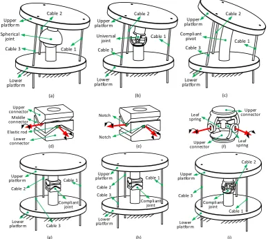
Figure 1. Examples of 2-DoF manipulators: a) the Omni-Wrist III pointing device [22]; b) spherical parallel manipulator (Agile Wrist manipulator) [23]; c) 2-DoF spherical parallel manipulator (2-DoF SPM) [24]; d) ankle-foot neuro-rehabilitation robot(CNR-ITIA) [25].
[image:3.595.103.492.378.724.2]To address these challenges, in this paper, a new class of 2-DoF tendon-driven manipulators with central supports (rigid or compliant joints) and three/more tendons are proposed, which can be utilized as high-speed rotational platform, robotic joint and positional mechanism (
Figure 2). More importantly, the proposed designs have the advantage of simple structure and relatedly low tolerance requirements, which enables low-cost manufacturing and assembly and the stiffness can be adjusted by varying the cable stiffness.
Spherical joint
Cable 1
Lower platform
Upper platform Upper
platform
Cable 2
Cable 3
Universal joint Cable 3
Cable 1 Cable 2
Lower platform
Upper platform Compli ant
pivot Cable 3
Lower platform
Cable 1 Cable 2
(a) (b) (c)
Elastic rod Upper connector
Lower connector
Middle connector
Upper platform
Lower platform
Cable 1 Cable 2
Cable 3 Compli ant
joint
(d) (e) (f)
(g) (h) (i)
Notch
Notch
Upper platform
Lower platform
Cable 3
Compli ant joint Cable 1 Cable 2
Leaf spring
Leaf spring
Upper platform
Lower platform
Cable 2
Cable 3
Compli ant joint
Cable 1 Upper connector
Upper connector
detail structure description of elastic-rod compliant universal joint; e) the detail structure description of notch compliant universal joint; f) detail structure description of leaf spring compliant universal joint; g) the elastic-rod compliant universal joint base central
support; h) notch compliant universal joint based central support; i) leaf spring compliant joint based support.
Specifically, the manipulator can be structured by the following configurations:
1. Rigid spherical joint or universal joint: Figure 2 (a) and (b) present the rigid spherical joint and universal joint based central support of the 2-DoF manipulator respectively where the tendons can be cables/ elastic rods. At least three tendons need to be used to drive the rotation of these 2-DoF tendon-driven manipulators, which can be equally spaced around the central support for the better stiffness performance. The design can be utilized for walking robot joints/rotational platform where is not supposed to be applied with high torque on the third DOF rotation direction.
2. Compliant pivot joint: Figure 2 (c) describes the compliant shaft joint based central support of the 2-DoF manipulator for light-weight duty applications (a twisting angle can be generated along the normal direction of the upper platform, if a large torque is applied). A compliant pivot is used to connect the upper and lower platform together to simplify the structure and decrease the cost at the same time. Several elastic materials can be used as the central support (e.g. super-elastic Nitinol, nylon and carbon fiber).
3. Compliant universal joint: Figure 2 (d), (e) and (f) are the compliant universal joint based central support for the 2-DoF manipulators. The elastic rods, notches and leaf springs are used to provide corresponding rotation motion (note that an appropriate stiffness should be considered for the three compliant joints), also minimizing the twisting along the normal direction of the upper platform and taking larger load by the parallel joints structure.
Figure 2 (g), (h) and (i) are the structure description of the 2-DoF manipulators using the elastic rods, notches and leaf springs joints respectively.
3 Kinematic and stiffness models
Since a class of new tendon-driven mechanisms is proposed, the kinematic and stiffness model, as well as the force model on the end-effector, are needed to be developed, which can be utilized for analyzing the position deflection at the end-effector when external forces is applied. Further, the stiffness and force models established in this paper can be utilized in any 2-DoF tendon-driven parallel kinematics mechanism with a central based support to analyses the stiffness variation and position deviation for the configurations proposed in this paper.
3.1 Kinematic model
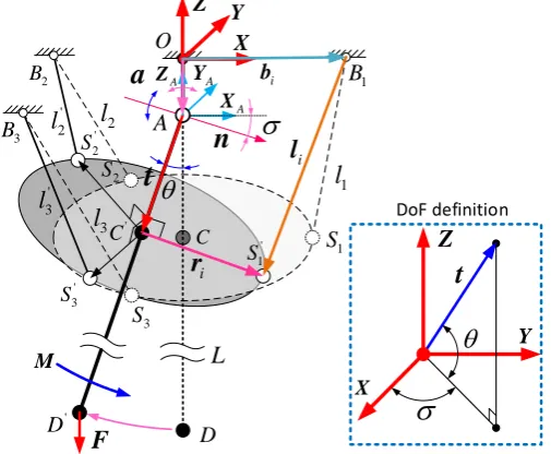
The kinematic analysis, as a necessary step before the stiffness analysis of the class of the manipulators, is briefly introduced to establish the relation between the input parameters (i.e. lengths of the tendons) and the output parameters (i.e. the orientation of the upper platform). Figure 3 illustrates the kinematic model of the TDPKM, in which two configurations are plotted, one is the initial configuration (i.e. the TDPKM is vertical downward), and the other one is a configuration with some degree of rotation. In order to establish the kinematic calculations of the TDPKM, two coordinate systems are defined in this paper and they are expressed as follows:
The manipulator coordinate system {O} is located at the upper plate, which is used for defining the position parameters of all the key points. The origin of the coordinate system is located at intersection point of joint axis and upper plate. The positive X direction is defined from the origin point to the base point B1. The positive Z
defining the motion of the TDPKM. In the original condition,{A} is parallel with the coordinate system {O}. 2 S 1 B 1
l
2l
A D X 3 B 2 B Z 3 SC ' S1
[image:5.595.173.426.94.302.2]1 S ' 2 S ' 3 S ' C
Y 3l
A X A Y A Z ' D ' 2l
' 3l
n
t
i b ir
O il
F
M L
a
X Z Y
DoF definitiont
Figure 3. Kinematic and static model of the TDPKM
The 2-DoF TDPKM proposed in this paper can adopt different kinds of central supports for different applications, however, due to their respective motion characteristics of different center supports, the methods in establishing the kinematic models should be different. For the concepts employing a spherical joint, Figure 2 (a), and compliant pivot, Figure 2(c), the tilt and torsion angles can be utilized for the motion definition [26]. In contract, for the rest of the manipulators (Figure 2), the conventional methods (e.g. DH method) in defining the rotations of joints should be adopted.
In this paper, the method based on the tilt and torsion angle is used to establish the kinematic model for the following stiffness analysis [26]. The detail processes can be divided into two steps: the first step is to define the tilt axis; the second step is to define the rotation angle around the tilt axis. In a more conventionally way, the tile angle, 𝜎, and torsion angle, 𝜃, are adopted to define the motion of the 2-DoF manipulator when the initial posture is specified (Figure 3). The transformation matrix, 𝑹, can be established.
x x x y z x z y
x y z y y y z x
x z y y z x z z
k k vers
c
k k vers
k s
k k vers
k s
k k vers
k s
k k vers
c
k k vers
k s
k k vers
k s
k k vers
k s
k k vers
c
+
−
+
=
+
+
+
+
−
+
R
(1)Where, 𝑠𝜃 = 𝑠𝑖𝑛𝜃, 𝑐𝜃 = 𝑐𝑜𝑠𝜃, 𝑣𝑒𝑟𝑠𝜃 = 1 − 𝑐𝑜𝑠𝜃. 𝜃 is the rotation angle around the tilt axis. 𝑘𝑥, 𝑘𝑦, and 𝑘𝑧 are the three components of the tilt axis, 𝒏, which can be expresses as:
T
x y z
k k k
=
n (2)
The closed loop vector of one tendon in the TDPKM can be used to establish the kinematic equation, and the vector of the tendon can be expressed as follows:
(
)
i
=
+
i+ −
il
R t
r
d
b
(3)Where,
𝒍𝒊 is the position vector of the leg in manipulator coordinate system {O}
𝒕 is the position vector of the center point of lower plate in joint coordinate system {A}
𝒃𝒊 is the position vector of the tendon fixed point in upper plate in the coordinate system of {O} The length of the i-th tendon can be expressed as:
i i
l
=
l
(4)After calculated the rotation matrix 𝑹 of the TDPKM, all the parameters in key points can be calculated when the rotation motion is specified in the coordinate system {O}. Then the workspace can be calculated and plotted to ascertain the working range of the TDPKM, as well as the basic parameters for the stiffness modeling can be achieved. The length of the three tendons can also be calculated, which will be used for the following experimental configurations.
For the stiffness analysis, the configuration of manipulator is specified firstly by giving the parameters of, 𝒏, and, 𝜃, and then the stiffness model was established in the following section by using the kinematic parameters obtained in this section (i.e. fixing points in upper and lower platform, vector and length of driving cables and rotation matrix of manipulator).
3.2 Stiffness model
The stiffness model presented in this section can be utilized to calculate the stiffness of the TDPKM at any specific configuration. One novelty for the stiffness model is that three components (i.e. tendon stiffness, structural stiffness (i.e. determined by the configuration of the mechanism) and central support stiffness) are considered for calculating the stiffness of the whole system; another novelty is that the tension of the tendons can be controlled actively by employing a central support (compared to the cable driven manipulators without a central support), which enable the system for different tasks with different stiffness (e.g. low stiffness in human collaborative operation, enabling safer environments; large stiffness in high positional accuracy applications without any human working with the robot); while in most of the rigid limb based 2-DOF manipulators, the stiffness of the limbs is constant, rendering the system stiffness cannot be actively adjusted.
When it comes to the stiffness analysis of the TDPKM, there are two main factors actively affecting the stiffness of the whole system. One is the stiffness of the tendon (Figure 6), which is relevant with the tension (affected by the load at the end-effector). The last factor is the structural configuration of the TDPKM. As the length of tendons, as well as the Jacobian matrix, changes under different system configurations, the stiffness of the whole system varies as a result.
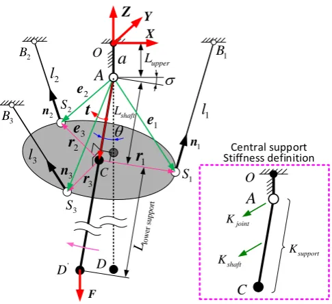
According to the literature, there are several criteria for evaluating the mechanism stiffness, including the trace of the stiffness matrix [27], the eigenvalues of the stiffness matrix [28], the determinant of the stiffness matrix [29] and the position deviation evaluation under external dead weights. In this paper, the position deviation caused by payload applied at the manipulator tip was chosen as the criteria, which was also utilized to validate the stiffness analysis, to evaluate the stiffness of the TDPKM (by comparing the difference between the theoretical calculation and experimental results) under different system configurations.
shaft L X 1 S 2 S 3 S 3 B 2
B B1
1 n 2 n 3 n 3
l
1l
2l
O CA
1r
2r
3 r D F Z upper Lt
1e
2 e 3e
low er su [image:7.595.176.419.77.299.2]pp ort L
' D Y
a
support K shaft K joint K OA
Central support Stiffness definition CFigure 4. Schematic of the static configuration of TDPKM
Thus, the static equation of the TDPKM can be expressed as Eq.(5) by establishing the force and moment balance equation on point 𝐴. (the validation of Eq.(5) can be found in the appendix).
3 1 1 3 1 1
0
0
i s i i i i = =
+
+
=
+
=
f
f
F
e
f
M
(5)
Where,
𝒇𝑖 is the driving force in i-th tendon
𝒇𝑠 is the supporting shaft force (between point 𝐴 and point 𝐶) 𝑭1 is the external force vector in the manipulator coordinate system {O} 𝑴1 is the external moment vector in the manipulator coordinate system {O}
𝒆𝑖 is the position vector from the center of spherical joint to the i-th tendon fixed point.
As the supporting shaft force, 𝒇𝑠, is passing through point 𝐴, the moment component produced by the supporting shaft force can be regarded as zero. In addition. Thus, Eq.(5) can be further expressed as matrix form:
=
T
J f W
(6)Where, 𝑾 is the wrench on the TDPKM and can be expressed as: 𝑾 = [−𝑭1− 𝑴1]𝑇. 𝒇 is the driving force matrix constituted by the three tendons and force in supporting shaft. 𝑱 is the Jacobian matrix of the TDPKM, and it can be expressed as:
1 2 3
1 1 2 2 3 3
=
sT
n
n
n
n
J
e
n
e
n
e
n
0
(7)Where, 𝒏1, 𝒏2 and 𝒏3 are the unit vectors of tendons 1, 2 and 3 respectively; 𝒏𝑠 is the unit vector on center support; 𝒆1, 𝒆2 and 𝒆3 are the position vectors from center of spherical joint to the three tendon attaching points 𝑆1, 𝑆2 and 𝑆3 respectively (Figure 4).
with respect to the motion vector of manipulator.
( )
1 2=
=
T
+
T=
+
W
f
K
J
J
f K
K
S
S
S
(8)Where, 𝑺 is the motion vector of the general parallel manipulator, which can be expressed as 𝑺 = [𝒅𝑇 𝝍𝑇]𝑇(𝒅 is the translational vector and 𝝍 is the rotational vector of system). 𝑲
1 is the stiffness matrix produced by the elongation of the tendons, which is denoted as the tendon stiffness. 𝑲2 is the stiffness matrix produced by the structure of the TDPKM, which is denoted as the structural stiffness.
For the tendon stiffness, the expression can be organized as follows:
1
=
=
( ,
1 2,
3)
T T T
diag k k k
d
=
f
f
l
K
J
J
J
J
S
l
S
(9)Where, 𝒍 is the vector constituted by the length of three tendons. 𝑘1, 𝑘2 and 𝑘3 are the stiffness of the three tendons. The tendon stiffness with the relationship of tendon length will be tested later in this paper (Figure 6).
For the structural stiffness, which is related with the TDPKM configuration. The process in simplifying the expression is complicated comparing with the tendon stiffness, which is shown as follows:
( )
1 2 32
1 1 2 2 3 3
=
T=
s
n
n
n
n
K
J
f
f
e
n
e
n
e
n
0
S
S
(10)In Eq.(10), the expression can be further expanded as:
=
+
+
+
i i
i
i
i i i i i i i i
i i i i i i
=
n
n
n
n
S
d
ψ
e
n
e
n
e
n
e
n
S
n e
n e
n e
S
S
d
d
ψ
ψ
(i =1,2,3) (11)
As the TDPKM can only realize the rotational movement around the spherical joint, which means that the componential parts relating to the translation vector, 𝒅, should be zero matrix. In addition, the rotational vector,
𝝍, in TDPKM can be expressed as 𝝍 = [𝜃 𝜎]𝑇(𝜃 is the torsion angle and 𝜎 is the tilt angle as shown in Figure 4). Then Eq.(11) can be further simplified as:
+
i
i
i i i i
i i
=
n
0
n
ψ
e
n
e
n
S
0
n e
ψ
ψ
(i=1,2 ,3) (12)
It can be seen from the structure of the stiffness matrix in Eq.(12) that the top right part is the displacement induced by the rotation of the moving platform. In whole motion of the TDPKM, only the rotational motion can be realized around the spherical joints, while the translational motion is restricted. Thus, the top right part of the
stiffness matrix (𝜕𝒏𝒊
𝜕𝝍) in Eq.(12) is zero, which is derived from the following part (as shown in Eq.(13) to Eq.(16)).
When the moving platform rotates around the spherical joints with an increment 𝝍, the related displacement caused by the rotational increment can be expressed as ∂𝒅 = ∂𝒆𝑖= ∂𝝍𝑖× 𝒆𝑖, then
(
)
(
)
=
=
=
=
i i
i i i i i i i i
e
ψ e
n
n
I e
n n
e
I
n
e
ψ
ψ
(13)(
)
(
)
=
=
i i i i i
i i i i i i
i
= −
=
n
n
ψ e
n
n
e
e
e
I e
e
e
I
0
ψ
ψ e
ψ
d
d
(14)As a result, the structural stiffness matrix can be written as:
3 2
1
=
i i i
i
f
=
0
0
K
0
n
e
(15)Where, 𝒏𝑖× and 𝒆𝑖× are the skew-symmetric matrix of the 𝒏𝑖 and 𝒆𝑖 respectively. The skew-symmetric
matrix expression of 𝒏𝑖 is shown as Eq.(16) and the skew-symmetric matrix expression of 𝒆𝑖 is defined as the
same way.
0
0
0
iz iy
i iz ix
iy ix
n
n
n
n
n
n
−
=
−
−
n
(16)Further, as there is a support located at the center of the TDPKM, where the deformation will be caused in the center support when the external load is imposed on. The stiffness of the center support can be expressed as
[30]:
3
=
T
support support support
K
J
K
J
(17)Where, 𝑱𝑠𝑢𝑝𝑝𝑜𝑟𝑡 is the Jacobian matrix relating from the velocity of the moving platform to the center shaft velocity. As the moving platform is connected to the central shaft, the Jacobian matrix, 𝑱𝑠𝑢𝑝𝑝𝑜𝑟𝑡, can be defined as the identity matrix.The central support stiffness, 𝑲𝑠𝑢𝑝𝑝𝑜𝑟𝑡, includes the stiffness of shaft and the joint (Figure
4), which is composed of three components in diagonal matrix (i.e. the rotational stiffness in two orthogonal axes and longitudinal stiffness respectively). Hence, for the spherical joint and universal joint based central supports (i.e. Figure 2 (a) and (b)), the stiffness matrix of the central support can be established as Eq.(18):
(
)
(
int_ int_ int_)
=
T1 1
+
support
diag K
jo xK
jo yK
jo zL
shaftEA
K
R
R
(18)Where, 𝐾𝑗𝑜𝑖𝑛𝑡_𝑥 and 𝐾𝑗𝑜𝑖𝑛𝑡_𝑥 are the rotational stiffness of joint in two orthogonal axes; 𝐾𝑗𝑜𝑖𝑛𝑡_𝑧 is the longitudinal stiffness of joint; 𝐸 is the elastic modulus of the central shaft. 𝐴 is the cross-sectional area of the central shaft. 𝐿𝑗𝑜𝑖𝑛𝑡 is the length of the central shaft.When the compliant shaft-based central support (Figure 2 (c)) is considered, the stiffness matrix of central support can be expressed as:
(
)
=
T2
2
support
diag EI
L
shaftEI
L
shaftEA L
shaftK
R
R
(19)Where, 𝐼 is the moment of inertia. In Eq.(20), 𝐸𝐼 2𝐿⁄ 𝑠ℎ𝑎𝑓𝑡 is the rotational stiffness of compliant shaft, and 𝐸𝐴 𝐿⁄ 𝑠ℎ𝑎𝑓𝑡 is the compression stiffness of compliant shaft (Figure 4).
Then the whole stiffness of TDPKM 𝑲 can be expressed as:
-1 -1-1
1 2 3
=
+
+
K
K
K
K
(20)After calculating all the three-component stiffness, the stiffness of the whole system can be calculated within the workspace. Then the theoretical derivation of the stiffness model presented in the previous will be validated with the experimental results in the following sections.
4 Stiffness model validation
The stiffness model of the class of TDPKMs has been established with the consideration of three-component stiffness (tendon stiffness, structural stiffness and central support stiffness respectively) in previous section. After that, a set of simulations and physical experiments were conducted for validating the stiffness model developed in this paper.
4.1. Test rig design
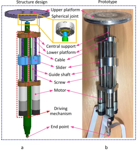
In order to physically validate the stiffness model, a case study is presented. A spherical joint tendon driven manipulator was built, since it has high stiffness (compared with compliant joint tendon driven mechanism) and good reliability (compared with universal joint and compliant shaft), which allows to hang a large range of dead weight at the tip for validating the stiffness analysis. The structure design and the prototype of the TDPKM are shown as Figure 5. The mechanism can be utilized as robot joint [31] and positioning system. Specifically, by combining a group of this manipulators, a walking robot can be formed with its upper platform fixed to the robot body [32]; while, by fixing the lower platform, a 2-DoF positioning system can be structured.
Central support
Cable
Screw Slider
Motor Structure design
Lower platform
Guide shaft
Prototype
Spherical joint
End point Driving mechanism
Upper platform
[image:10.595.180.415.391.650.2]a b
Figure 5. a) Schematic design and b) prototype of the TDPKM. Note: the upper platform is fixed while the lower platform is free to move, which can be utilized as robot joints. In addition, the dead weight can be hanged at the end-point to provide the external
force.
linear motion of the tendons (one end of the tendon is connected to the driving mechanism and the other end is attached to the upper platform), then the rotational motion of the upper platform around the spherical joint can be realized by adjusting the lengths of the three tendons.
4.2 External force model establishment
The stiffness model has been established in the previous section, and it was used in this section to analyze the stiffness variation for the TDPKM among the workspace. Three steps are involved for the stiffness model validation: Firstly, the external forces are calculated and transferred to the manipulator coordinate system {O} as the generalized force, 𝑭, and moment, 𝑴, as the external forces; then, the stiffness model established in the previous section is used to analyze the stiffness and the corresponding deviations in any specific positions; at last, the experiment is implemented with the same configuration as theoretical calculation to test the deviations at the end-effector, and the results were compared with the theoretical calculations.
Providing a constant dead weight is imposed at the end of the TDPKM, it produces the external force (F and
𝑴) in the manipulator coordinate system, and then the three tendons can produce the pulling forces to balance the external force. As the TDPKM can only rotate around the spherical joint, it is chosen as the balance point for establishing the static equation.
The generalized force 𝑭𝑒 and moment 𝑴𝑒 at the spherical joint under the external force can be expressed as (Figure 3):
cos sin
sin
sin
cos cos
cos cos
cos sin
x
e y
z
z y
e x z
y x
F
F
F
LF
LF
LF
LF
LF
LF
=
+
=
−
−
−
F
M
(21)
Where, 𝐹𝑥, 𝐹𝑦 and 𝐹𝑧 are the three components of the force. 𝐿 is the length from the center of the
spherical joint to the end (dead weight point), and it can be expressed as 𝐿 = 𝐿𝑗𝑜𝑖𝑛𝑡+ 𝐿𝑙𝑒𝑔, 𝜃 and 𝜎 are the
torsion and tilt angles of the TDPKM (Figure 3).
As the lower parts (i.e. motors and center shaft) of the TDPKM are also subject to the gravity, which will cause the external force in the manipulator coordinate system {O}. Then, the whole generalized force (include the force and moment), 𝑾, can be expressed as:
e w
=
+
W
W
W
(22)Where, 𝑾𝑒 is the generalized force caused by the external force. 𝑾𝑤 is the generalized force caused by the dead weight of the lower parts of TDPKM.
Then the generalized force constituted by the weight of lower parts of TDPKM and external dead weight will be used as the external force in Eq.(10) to calculate the pulling forces in the three tendons, as well as calculate the stiffness of the tendon using (Figure 6).
4.3
Stiffness model validation of the manipulator
Then, the calculated deviations were compared with the simulation and experimental results for validating the stiffness model. Further, from the position deviations, it can be found the stiffness modelling is essential to be considered for the position control of the manipulator.
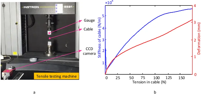
a. Cable stiffness measurement
Firstly, as the key element for the stiffness model validation, the cable stiffness was measured. Figure 6
presents the tension testing experiment for achieving the stiffness of the tendon under different tensions. The tensile machine (Figure 6 (a)) was used to measure the pulling forces on the tendon and measure its elongation. As an example, the parameters of a tendon used in the TDPKM and experiment are as follows: the diameter is 0.6 mm; length is 120 mm; the material is stainless steel [8].
0 50 150
5
×104
Tension in cable (N)
St
if
fn
es
s
o
f
ca
bl
e
(N
/m
)
100 0
4
D
ef
or
m
at
io
n
(
mm
)
2
1 3
4
3
1 2
25 75 125
Cable Gauge
CCD camera
Tensile testing machine
[image:12.595.95.504.240.431.2]a b
Figure 6. Example of tension testing experiment and tendon stiffness. a) the tendon is tested in the tensile testing machine; b) the stiffness and deformation of the tendon (blue line and red line respectively) with the relation of tension.
The stiffness of the tendon under different tensions were calculated and plotted after getting the deformation under the corresponding pulling forces (Figure 6 (b)). The variation of the tendon stiffness with the increase of tension is not linear for the whole tensile process, and there is a drop in the initial stage of the stiffness curve. Because the tendon is not tensioned in the initial stage, so the gauge moves up forwards, but the disproportional tension force was measured. Once the tendon gets fully tensioned (8N), its stiffness is close to be linear. In the initial stage of Figure 6 (b), the stiffness is dropping from the initial point from 2.9 e+4 (N/m) to the bottom (1.5 e+4 (N/m)) under the tension about 8 N, and then the stiffness is jumping up with the increase of tendon tension. The stiffness curve will be used to calculate the stiffness of the tendons in TDPKM for establishing the stiffness model.
b. Simulation and physical experiments of the positional deviation
After ascertaining the whole generalized force and moment caused by different dead weights, Eq.(21), the driving forces in the three tendons can be calculated by using Eq.(6), which was utilized to calculate the stiffness of the tendon (Figure 6).
or two tendons get slack, which affects the accuracy of the measurements. In order to avoid the slacks occur in tendons and increase the stability of TDPKM, the additional tensions are imposed in proportion on the three tendons.
[image:13.595.84.511.188.384.2]The TDPKM is configured with the upper platform fixed (denoted as the base spherical joint), and the body can be driven to realize the rotation around the spherical joint for the following experiments. The parameters of the TDPKM are shown as Table.1.
Table.1 Parameters of the CDSD for the stiffness analysis
Variables Variable description Value Unit
b1 The coordinate of base spherical joint B1 in {O} [24, 0, 0] mm
b2 The coordinate of base spherical joint B2 in {O} [-12, 20.8, 0] mm
b3 The coordinate of base spherical joint B3 in {O} [-12, -20.8, 0] mm
s1 The coordinate of lower spherical joint S1 in {A} [24, 0, 0] mm
s2 The coordinate of lower spherical joint S2 in {A} [-12, 20.8, 0] mm
s3 The coordinate of lower spherical joint S3 in {A} [-12, -20.8, 0] mm
Lupper The length of upper spherical joint 6 mm
Ljoint The length of lower spherical joint 29 mm
Lleg The length of the leg 190 mm
mleg Mass of leg 1 Kg
pleg Coordinate of the leg centroid in {A} [28, 91, 0] mm
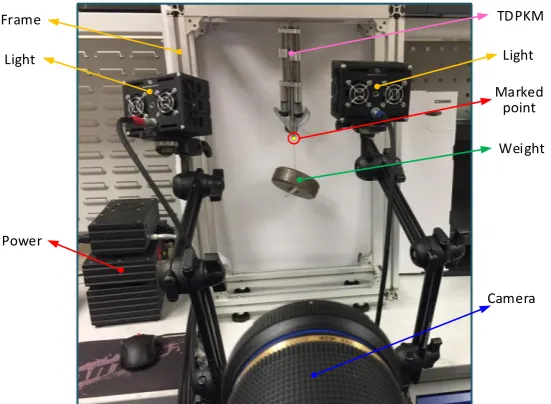
The experimental setup is shown as Figure 7, in which a frame box is used to provide the support for the TDPKM, as well as easy operation for the experiment. The frame is fixed on the vibration isolation table and adjusted to be levelling before the configuration of TDPKM, then the upper platform of the TDPKM is fixed on the top plate of the frame box, and different dead weights are hanged at the end of the TDPKM.
Light
Weight
Power
Camera TDPKM
Light Frame
Marked point
Figure 7. The experimental setup for the stiffness test of TDPKM
[image:13.595.162.438.485.687.2]detection camera (type: MotionPro Y4-S2) was used to measure the deflection of the TDPKM with different dead weights at the end, which is marked as the point to measure the position with the reference point.
[image:14.595.141.454.181.221.2]In the experiments for the TDPKM, the tilt angle is set under the following points, and they are 0°, 30°, 60° and 90°, respectively.At each selected tilt angle, the torsion angle varies from -30° to 30° with the increment 2°. Table.2 presents the experimental arrangement for the deviation test of the TDPKM.
Table.2 Experiment variable arrangement Parameter Tilt angle
(degree)
Swinging angle (degree)
Increment (degree)
Weights (Kg) Value 30 [-30, 30] 2 0.5, 1, 2
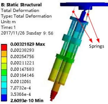
Further, the position deviation of TDPKM (between the tip positions under zero gravity and normal gravity) under different dead weight was simulated by ANSYS. A static structural model was used to implement the simulation, and the 3D model of the manipulator was imported into ANSYS. Then the corresponding material properties were assigned to the different parts. After that, three springs (emulating the actuating cables) with different stiffness were assigned between the upper platform and base connections. At last, the supports (fixed supports on the upper platform and gravity supports on the base) were given to the different parts. After solving the model, the position deviation at the end-point can be measured (Figure 8).
[image:14.595.205.388.354.531.2]Springs
Figure 8. The simulation result using the ANSYS software. Note: here the torsion angle is 20° and the tilt angle is 0°
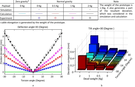
Finally, the results of the position deviation (between the tip positions under zero gravity and normal gravity) from calculation, simulation, and physical experiments were utilized for cross checking the stiffness model developed in this paper. Figure 9 (a) presents the position deviation of the manipulator caused by end load, which is used as the criteria to evaluate stiffness of the TDPKM between the theoretical calculation and experimental test, with the change of torsion angle (from -30° to 30°) from the initial angle 0° (the upper and lower platforms parallel to each other in the initial angle). The solid points were determined from simulation by ANSYS, the solid lines were calculated by using the theoretical method presented in this paper and the circles are obtained from the experiments measured by using the motion camera (Figure 7). The different colors (blue, red, pink and black) for the points and lines represent the different dead weights hanged at the end of the TDPKM (0 Kg, 0.5 Kg, 1 Kg and 2 Kg respectively).
calculations presented in this paper. In Figure 9 (a), the maximum deviations are about 2mm, 3.6 mm, 5.3 mm and 8.5 mm with 0 Kg, 0.5 Kg, 1 Kg and 2 Kg dead weights, respectively, which are significantly different with the zero-gravity position; thus, the stiffness model has to be considered in the control of the manipulator, in order to increase the positional accuracy. Figure 9 (b) illustrates the error between the theoretical calculations and experiment tests under different torsion angles and dead weights, and the whole error is within the limit of ±0.6 mm (the average errors at the four different dead weights are 3.1%, 3.8%, 2.5% and 4.2% respectively), which proves the validity of the theoretical calculations presented in this paper. The error in each dead weight is raising with the increase of the torsion angle (0° torsion angle is regarded as the start and increases to the left (-30°) and right (30°)).
Zero gravity* Normal gravity Note
Payload 0 Kg 0 Kg 0.5 Kg 1 Kg 2 Kg The weight of the prototype is
1.5kg, it also generates a part of the resultant deviation, which was considered in the simulation and calculation Simulation
Calculation Experiment
*No cable elongation is generated by the weight of the prototype.
-30 -14
14 30
0 0.5 1
2 0 0.2 0.4 0.6
Dead weight (Kg)
D
e
v
ia
ti
o
n
c
o
m
p
a
ri
so
n
(
mm
)
Tilt angle=30 (Degree )
[image:15.595.67.537.236.538.2]a b
Figure 9. An example of the position deviations of the TDPKM (between zero and normal gravity). a) the position deviations with different dead weights (tilt angle, 30°). b) the deviations comparison between the experiment result and theoretical calculation
According to the comparisons between the theoretical calculation, simulation and physical experiments, it proves the stiffness model developed in this paper can be used to analyze the stiffness of the class of the proposed tendon-driven 2-DoF manipulators. Further, it can be utilized to compensate the position deviation caused by the end load, so that the positional accuracy of the manipulator can be improved.
4.4 Position deviation of the manipulator among the workspace
Since the theoretical stiffness model has been validated with the experiments and simulation, it was unlisted to analyze the end effector deviation within the workspace. In previous section, only the deviations of TDPKM at some points are analyzed with fixed tilt angles, while in this section, the deviation of the TDPKM within the whole workspace were calculated and plotted to analyses the deviation variation.
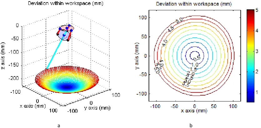
Figure 10 presents the position deviation of TDPKM among the whole workspace. The workspace is scattered
-30 -20 -10 0 10 20 30
0 2 4 6 8
Torsion angle (Degree)
P
o
s
iti
o
n
d
e
v
ia
tio
n
(
m
m
)
by the two variations in TDPKM (tilt angle, 𝜎, and torsion angle, 𝜃), where the tilt angle is ranging from 0° to the 360° and the torsion angle is ranging from 0° to 30°, and then the theoretical method presented in this paper is used at these scattered points to calculate the corresponding position deviation with 1 Kg dead weight.
Figure 10 (a) shows the position deviation map of the TDPKM among the workspace, in which the position deviation is calculated in the scattered point as the color bar value for plotting the workspace. The different colors in the map means that the position deviations are different, and the values are calibrated by the color bar located at the right part of the figure. It can be seen from Figure 10 (a) that the position deviation of the TDPKM is influenced by the torsion angle. With the increase of the torsion angle, the position deviation increases correspondingly. As the workspace of the TDPKM is a kind of spherical shape, the position deviation map is distributed in a corresponding spherical shape.
a b
Figure 10. The position deviation and counter maps of the TDPKM within the workspace. a) position deviation map of the TDPKM with the machine sketch. b) contour map of the position deviation in the workspace (1 kg payload)
Figure 10 (b) presents the contour map of the position deviation from the front view of the position deviation map. The position deviation is lower when the TDPKM is working within the center area of the workspace, while it deteriorates when the TDPKM is closing to the edge of the workspace. The reason for the increasing position deviation near the edge of workspace is that the length of driving cables is differing greatly with each other, which will cause the decreasing of the stiffness in one or two cables, as well as the whole stiffness of TDPKM. Further. It can also be seen from the shape (the shape is not a standard circle) of the contour map that the position deviations are varying under different tilt angles, since the structure of TDPKM is changing under different torsion angles.
The stiffness model presented in this paper is validated in this section by a set of simulation and physical experiments, and it can be found that, the average error between the theory calculations and experiment tests at the tested points is 3.4%. Further, the stiffness model was utilized to study the position deviation of the manipulator within the whole workspace, which supports the development of the deviation compensation algorithm for the future study.
5. Conclusion
can be structured with low manufacturing cost and assembling difficulties. The central support, which can be selected from a large range of different pivot joints (i.e. rigid spherical joint or compliant joints), locates at the center of the TDPKM to connect the upper and lower platform, providing a way to actively adjust the stiffness of the manipulators by varying the forces among the tendons (e.g. cable and elastic rod).
Since a unique class of TDPKMs are introduced, the kinematic model was developed firstly. Then, the stiffness model, which considers tendon stiffness, structural stiffness and central support stiffness, is established and validated by the simulations and experiments separately. It can be found that the deviation (i.e. between the real positions of the manipulator tip and the ones under zero gravity) calculated by the stiffness model of TDPKM can match with the simulation and experiment results under different end loads (0 Kg, 0.5 Kg, 1 Kg and 2 Kg respectively) (Fig.9). The average errors are 1.5% (theoretical results versus simulation) and 3.4% (theoretical results versus experiment) respectively under different payloads. Further, it can be seen that the deviations are significant (i.e. 2mm, 3.6 mm, 5.3 mm and 8.5 mm with 0 Kg, 0.5 Kg, 1 Kg and 2 Kg dead weights, respectively); thus, the stiffness model needs to be considered to increase the positional accuracy of the manipulator in the future research. After validating the model, it was utilized to investigate the stiffness variation among the whole workspace (Fig.10). The result shows that the position deviations of TDPKM varies among the different tilt angles (the maximum discrepancy is up to 1.4%), which indicates that the stiffness is inconstant during the circle movement (the tilt angle is changing but the torsion angle is constant) of TDPKMs.
Acknowledgment:
The research leading to these results has received funding from China Scholarship Council and University of Nottingham.
Reference
[
1] Raymond W. Blodgett Jr. Cable-driven extension mechanism for trailer slide-out[M]Google Patents,1994[
2] Adam Rushworth, Dragos Axinte, Mark Raffleset al. A concept for actuating and controlling a leg of a novel walking parallel kinematic machine tool[J]. Mechatronics. 2016. 40: 63-77[
3] Rodney G. Roberts, Todd Graham, Thomas Lippitt. On the inverse kinematics, statics, and fault tolerance of cable-suspended robots[J]. Journal of Field Robotics. 1998. 15(10): 581-597[
4] Marc Gouttefarde, David Daney, Jean-Pierre Merlet. Interval-analysis-based determination of the wrench-feasible workspace of parallel cable-driven robots[J]. IEEE Transactions on Robotics. 2011. 27(1): 1-13[
5] Paul Bosscher, Imme Ebert-Uphoff. Wrench-based analysis of cable-driven robots[M]. Robotics and Automation, 2004. Proceedings. ICRA'04. 2004 IEEE International Conference on IEEE,2004: 4950-4955[
6] Han Yuan, Eric Courteille, Dominique Deblaise. Static and dynamic stiffness analyses of cable-driven parallel robots with non-negligible cable mass and elasticity[J]. Mechanism and Machine Theory. 2015. 85: 64-81[
7] Bin Zhang, Wei-Wei Shang, Shuang Conget al. Size optimization of the moving platform for cable-driven parallel manipulators based on stiffness characteristics[J]. Proceedings of the Institution of Mechanical Engineers, Part C: Journal of Mechanical Engineering Science. 2017: 60034179[
8] S. H. Yeo, G. Yang, W. B. Lim. Design and analysis of cable-driven manipulators with variable stiffness[J]. Mechanism and Machine Theory. 2013. 69: 230-244[
9] Saeed Abdolshah, Damiano Zanotto, Giulio Rosatiet al. Optimizing Stiffness and Dexterity of Planar Adaptive Cable-Driven Parallel Robots[J]. Journal of Mechanisms and Robotics. 2017. 9(3): 31004[
11] Hamed Jamshidifar, Amir Khajepour, Baris Fidanet al. Kinematically-Constrained Redundant Cable-Driven Parallel Robots: Modeling, Redundancy Analysis, and Stiffness Optimization[J]. IEEE/ASME Transactions on Mechatronics. 2017. 22(2): 921-930[
12] Marc Arsenault. Workspace and stiffness analysis of a three-degree-of-freedom spatial cable-suspended parallel mechanism while considering cable mass[J]. Mechanism and Machine Theory. 2013. 66: 1-13[
13] Per Henrik Borgstrom, Brett L. Jordan, Gaurav S. Sukhatmeet al. Rapid computation of optimally safe tension distributions for parallel cable-driven robots[J]. IEEE Transactions on Robotics. 2009. 25(6): 1271-1281[
14] Y. Q. Ni, J. M. Ko, G. Zheng. Dynamic analysis of large-diameter sagged cables taking into account flexural rigidity[J]. Journal of Sound and Vibration. 2002. 257(2): 301-319[
15] Marco Carricato, Jean-Pierre Merlet. Stability analysis of underconstrained cable-driven parallel robots[J]. IEEE Transactions on Robotics. 2013. 29(1): 288-296[
16] S. Behzadipour, M. Azadi Sohi. Antagonistic stiffness in cable-driven mechanisms[M]. IFToMM World Congress, Besan{\c{c}}on, France, In,2007[
17] Cong Bang Pham, Song Huat Yeo, Guilin Yanget al. Force-closure workspace analysis of cable-driven parallel mechanisms[J]. Mechanism and Machine Theory. 2006. 41(1): 53-69[
18] Marc Gouttefarde, David Daney, Jean-Pierre Merlet. Interval-analysis-based determination of the wrench-feasible workspace of parallel cable-driven robots[J]. IEEE Transactions on Robotics. 2011. 27(1): 1-13[
19] Shabbir Kurbanhusen Mustafa, Sunil Kumar Agrawal. On the force-closure analysis of n-DOF cable-driven open chains based on reciprocal screw theory[J]. IEEE Transactions on Robotics. 2012. 28(1): 22-31[
20] Guilin Yang, Wei Lin, Mustafa Shabbir Kurbanhusenet al. Kinematic design of a 7-DOF cable-driven humanoid arm: a solution-in-nature approach[M]. IEEE/ASME International Conference on Advanced Intelligent Mechatronics (AIM), Monterey, CA, July,2005: 24-28[
21] Saeed Behzadipour, Amir Khajepour. Design of reduced dof parallel cable-based robots[J]. Mechanism and Machine Theory. 2004. 39(10): 1051-1065[
22] Xuechao Duan, Yongzhi Yang, Bi Cheng. Modeling and analysis of a 2-dof spherical parallel manipulator[J]. Sensors. 2016. 16(9): 1485[
23] J. Sofka, V. Skormin, V. Nikulinet al. Omni-Wrist III-a new generation of pointing devices. Part I. Laser beam steering devices-mathematical modeling[J]. IEEE transactions on aerospace and electronic systems. 2006. 42(2): 718-725[
24] Aibek Niyetkaliyev, Almas Shintemirov. An approach for obtaining unique kinematic solutions of a spherical parallel manipulator[M]. Advanced Intelligent Mechatronics (AIM), 2014 IEEE/ASME International Conference on IEEE,2014: 1355-1360[
25] Matteo Malosio, Simone Pio Negri, Nicola Pedrocchiet al. A spherical parallel three degrees-of-freedom robot for ankle-foot neuro-rehabilitation[M]. Engineering in Medicine and Biology Society (EMBC), 2012 Annual International Conference of the IEEE,2012: 3356-3359[
26] I. A. Bonev, D. Zlatanov, C. M. Gosselin. Advantages of the modified Euler angles in the design and control of PKMs[M]. 2002 Parallel Kinematic Machines International Conference on Citeseer,2002: 171-188[
27] Dan Zhang. Global stiffness modeling and optimization of a 5-dof parallel mechanism[M]. Mechatronics and Automation, 2009. ICMA 2009. International Conference on IEEE,2009: 3551-3556[
28] Bashar S. El-Khasawneh, Placid M. Ferreira. Computation of stiffness and stiffness bounds for parallel link manipulators[J]. International Journal of Machine Tools and Manufacture. 1999. 39(2): 321-342[
30] Xin Dong, Mark Raffles, Salvador Cobos Guzmanet al. Design and analysis of a family of snake arm robots connected by compliant joints[J]. Mechanism and Machine Theory. 2014. 77: 73-91[
31] D. A. Axinte, J. M. Allen, R. Andersonet al. Free-leg Hexapod: A novel approach of using parallel kinematic platforms for developing miniature machine tools for special purpose operations[J]. CIRP Annals-Manufacturing Technology. 2011. 60(1): 395-398[
32] Adam Rushworth, Salvador Cobos-Guzman, Dragos Axinteet al. Pre-gait analysis using optimal parameters for a walking machine tool based on a free-leg hexapod structure[J]. Robotics and Autonomous Systems. 2015. 70: 36-51Appendix
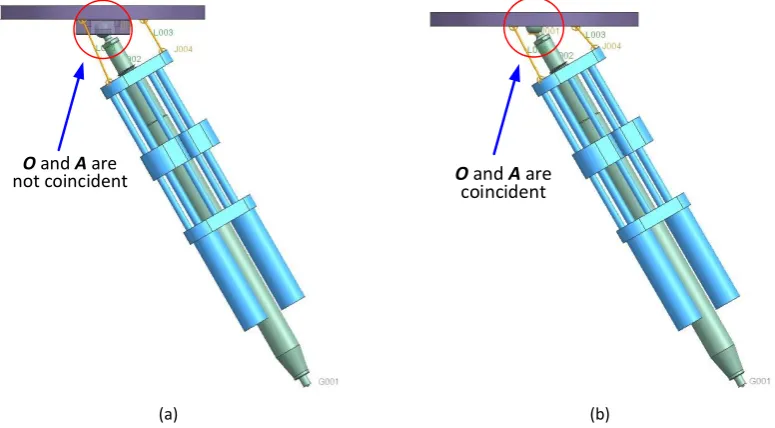
In order to validate Eq.(5), a simulation was conducted in UG (Unigraphics NX) to measure the driving forces along three cables by applying a torque, under two manipulator configurations (i.e. 𝑶 and 𝑨 not coincident ; 𝑶
and 𝑨 coincident), as shown in Figure 11. And then the simulation results are taken into Eq.(5) for cross checking.
O and A are
not coincident Ocoincident and A are
[image:19.595.105.493.310.524.2](a) (b)
Figure 11. Manipulator configuration for Eq.(5) validation. a) 𝑶 and 𝑨 are not coincident; b) 𝑶 and 𝑨 are coincident. Note: the 100 N·m torsion is imposed at the end of manipulator at these two configurations.
The driving forces along three cables and the central support are shown as table 3.
Table.3 Reacting forces in three cables and central support
Forces Forces in cables (N) Forces in the central support (N) Items Cable 1 Cable 2 Cable 3 𝐹𝑥 𝐹𝑦 𝐹𝑧
Configuration 1 -2.44 2.44 2.44 -0.7 0 2.38 Configuration 2 -2.64 2.44 2.44 -0.52 0 2.33
[image:19.595.126.470.619.684.2]1
1 2 3 3 3 2 1
1 1 2 2 3 3 3 3 3 1
s
f
f
f
=
n
n
n
E
F
e
n
e
n
e
n
0
M
f
(23)
Where, 1 2 3 3 3
1 1 2 2 3 3 3 3
n
n
n
E
e
n
e
n
e
n
0
, is Jacobi matrix;f
sis a 3X1 force vector.The Jacobi matrixes are calculated by using Eq.(23) under the two given manipulator configurations, which are shown as:
config_1
-0.5084
-0.3981
-0.3981
1
0
0
0
0
0
0 1
0
0.8611
0.9173
0.9173
0
0 1
0
19.0664
-19.0664
0
0
0
-23.7175 8.6193
8.6193
0
0
0
0
8.2748
-8.2748
0
0
0
J
=
(24)
config_2
-0.6522
-0.4597
-0.4597
1
0
0
0
0
0
0 1
0
0.7580
0.8881
0.8881
0
0 1
0
18.4579
-18.4579
0
0
0
-18.1924 10.6567 10.6567
0
0
0
0
9.5554
-9.5554
0
0
0
J
=
(25)