...
. ... ... ... ... ... ... ... ... ... ...
...
energy efficiency of residential tall buildings
in Saudi Arabia
*Corresponding author: noura.ghabra@gmail.com
Noura Ghabra
1,*, Lucelia Rodrigues
1and Philip Oldfield
21
Department of Architecture and Built Environment, Faculty of Engineering, University
of Nottingham, University Park, Room B04 Nottingham HOUSE, Nottingham NG7 2RD,
United Kingdom;
2School of Architecture & Design, Faculty of the Built Environment,
University of New South Wales, Room 2009 Red Centre, Sydney NSW 2052, Australia
Abstract
In this paper, the authors explored the hypothesis that the most common approach to improve a build-ing’s energy efficiency in the hot climate of Saudi Arabia, which focuses on engineering parameters, is not sufficient and architectural design parameters should be adopted to reduce cooling loads. In order to investigate this hypothesis, 27 sets of dynamic thermal simulations were compared. The best and worst combinations of glazing ratio, wall and glazing type were identified in order to understand the most influential parameter impacting the cooling energy loads in the building. The findings demonstrated that the reliance on a prescriptive approach for building envelope‘engineering parameters’specifications does not achieve the required levels of energy efficiency, and the thoughtful consideration of the‘design para-meters’, such as shading elements, could have a significant impact on cooling energy loads.
Keywords:energy efficiency; tall buildings; residential; façade design; building envelope Received 20 April 2016; revised 10 December 2016; editorial decision 2 March 2017
1
INTRODUCTION
In Saudi Arabia, 40% of the total energy is used by utilities (electricity and water), and 53% of this primary energy is con-sumed in the residential sector due to the significant use of air conditioning to cool indoor spaces [1]. This means that resi-dential buildings account for more than half of all delivered energy consumption across the country, and can be regarded as major contributors to carbon dioxide emissions arising from the combustion of fossil based fuels.
Rapid development in the region is strongly associated with tall building construction that led to the ascending race to build the world’s tallest building—currently the Kingdom Tower in Jeddah, which will rise over 1 km in height upon completion in 2018 [2]. Despite the fact that most of the tall buildings in the region are residential, very few studies have been conducted regarding the performance of this building type.
In addition to a building’s active systems, there are three other factors that have a major influence on a building’s energy use
[3]; (1) climate, (2) program (function and occupancy) and (3) building form (envelope, building shape and construction). Within the building’s envelope two sub-categories are identified [4]; building design parameters and engineering parameters. The building design parameters, such as the plan depth, interact with many other parameters and have an impact on the form and environmental performance of the building. On the other hand, the engineering parameters, such as the U-value of the wall, whilst it will have significant effect on the thermal performance, can take on values independently from other parameters.
The buildings’envelope is responsible for a significant portion of the total energy consumption in the built environment; a study in Hong Kong [5] has found that the building envelope design accounted for 36% of the peak cooling loads in office buildings. Another study [6] has simulated office buildings in Abu Dhabi, and found that the building envelope was responsible for 30% of the building’s total cooling loads (solar, glass and fabric).
However, the rapid urbanization in Saudi Arabia in addition to the availability of cheap heating and cooling energy has
International Journal of Low-Carbon Technologies 2017, 12, 411–419 © The Author 2017. Published by Oxford University Press.
resulted in an abundance of tall buildings with semi-transparent to fully glazed facades, which rely completely on extensive mech-anical air conditioning dependant on low cost, fossil fuel derived electricity. The timely work presented for the first time in this paper, explored the ability of utilizing the building envelope to reduce energy consumption, and therefore the reliance on fossil fuels, in residential tall buildings in Saudi Arabia. Saudi Arabia is one of the six Middle Eastern countries that form the Gulf Cooperation Council (GCC) political and economic alliance. All the six GCC countries could benefit from the results of this work, which could be used to inform future policy.
2
BUILDING REGULATIONS IN THE GCC
COUNTRIES
The development and implementation of building codes and standards should be one of the highest priorities to help reduce energy use and increase energy efficiency in buildings. Reflecting on the current energy regulations and the local green building codes and rating systems, it is apparent that the GCC countries have adopted a more pro-active approach toward environmental issues that started to set a trend amongst decision makers and developers in the region.
In the United Arab Emirates, the government of Abu Dhabi launched the Estidama Program and the Pearl Rating System, which are expected to be integrated into the building code in the near future. In Dubai, the Green Building Code (GBC) has been established and the Electricity and Water Authority issued the second phase of its Green Building Regulation in April 2010, aim-ing at reducaim-ing energy demand in new buildaim-ings by up to 40% [7]. In Qatar, there is an emerging GBC that is also promoting the Qatar Sustainability Assessment System (QSAS), an assessment tool for green buildings. Interestingly, the QSAS has also been developed into a regional code for the Gulf region under the name of Global Sustainability Assessment System (GSAS) soon to be adopted by other GCC countries as a regional green building code [8]. In Saudi Arabia, The Saudi Building Code (SBC) was devel-oped based on the International Code Council (ICC) and pub-lished in 2007. It included the Saudi Building Code Energy Conservation Requirements (SBC 601) that is based on the International Energy Conservation Code (IECC). These require-ments establish minimum performance-related regulations for the design of energy-efficient buildings and structures [9].
Generally, there are two approaches for compliance with building codes: the‘prescriptive approach’, which sets minimum requirements for the energy efficiency parameters of building envelopes and systems, and the ‘performance approach’ (also called the‘simulation method’or the‘building performance rating method’), which compares the performance of the proposed design with a similar building (standard design) whose enclosure elements and energy consuming systems are designed according to a reference requirement. The Saudi Building Code Energy Conservation Requirements (SBC601) and Dubai Green Building Regulations and Specifications (GBRS) [10] outline both
approaches for compliance, while the Estidama Pearl Building Rating System (PBRS) [11], used in Abu Dhabi, specifies a per-formance approach. The Global Sustainability Assessment System (GSAS) from Qatar introduces a new approach of setting min-imum target for energy performance at a building level [12].
In terms of façade design, the above mentioned codes, regu-lations and assessment systems only consider limited aspects of the thermal requirements of building envelopes, such as adjust-ing glazadjust-ing and wall thermal transmittance values [7]. Little consideration has been given to date to architectural design parameters such as shading, the balance between transparency and opacity, or diversity of building form and organization, all of which can have a significant impact on energy performance. This work attempted to bridge that knowledge gap using a gen-eric model based in Jeddah as a vehicle for investigation.
3
RESEARCH AIM, SCOPE AND METHOD
The aim of this study was to identify the limitations and com-pare the energy performance of relevant facade design strategies for residential tall buildings in the studied region. A hypothetical generic model was developed as a benchmark building that is representative of a residential tall building located in the city of Jeddah in Saudi Arabia. The following questions were explored:
(I) What is the impact of façade‘engineering parameters’on the thermal performance of tall buildings in Jeddah’s climate? (II) What is the most significant engineering parameter that
impacted the building’s thermal performance?
(III) What are the building envelope characteristics that deliver best energy efficiency considering tall building typology?
The scope of this work was limited to the thermal performance of the building as a result of the envelope’s ability to decrease thermal transmittance and solar heat gains. The results were analysed per orientation using annual cooling loads as a param-eter for comparison. A parametric study developed through advanced dynamic simulations was used to evaluate the impact of different tall buildings envelope combinations, selected based on the ‘engineering parameters’ specified in the local building codes and used in practice such as wallU-value, glazing shading coefficient and glazing ratio. A total of three different wall types, three different glazing types and three different glazing ratios were considered in the investigation. A sensitivity ana-lysis method was applied in which one parameter was varied each time while the others were kept fixed.
occupant comfort. The dynamic building simulations in Tas are conducted through an hourly analysis of the thermal state of the building throughout a typical year based on weather data selected by the user, which result in 8760 data outputs for each simulated variable [14].
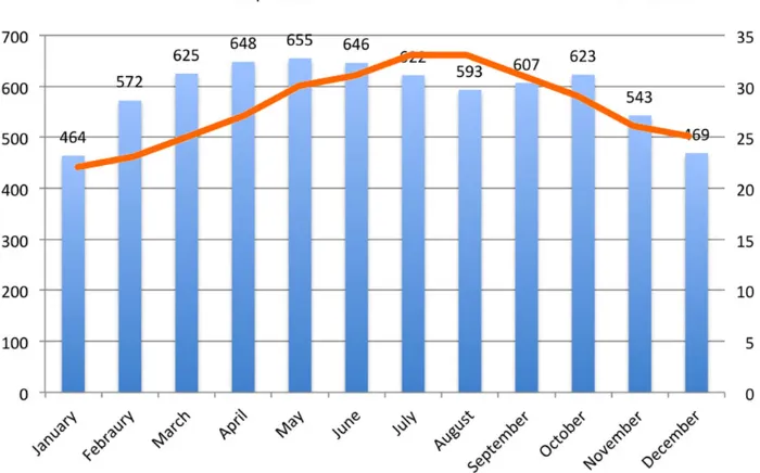
The city of Jeddah, located on the western coast of Saudi Arabia under tropical arid climate according to Koppen’s cli-mate classification, was the primary location for this work as it is growing into a future tall building hub in the region. A wea-ther dataset for Jeddah, containing the hourly data for one year (2005) provided by EnergyPlus, was used in the simulation. The analysis of Jeddah’s climate concluded that the climate is predominantly hot with relatively high relative humidity levels. Due to Jeddah’s latitude, nearly half of the year (from April till September) the sun is mostly in the northern part of the sky dome (Figure 1). In addition to the high solar altitude all year around, the clear and cloudless sky allows the abundant solar radiation to cause surface heating and raise the air temperature. Therefore, minimizing heat gains and maximizing heat loss are key considerations especially in the warmer seasons.
4
THE GENERIC MODEL
There are two methodologies underpinning the construction of a base case morphology: the existing base case and the concep-tual base case [15]. In the context of this research, a conceptual generic base case model was constructed as a hypothetical building compiled from extensive statistical data based on the findings of a qualitative and quantitative analysis of 12 residen-tial buildings in Jeddah, Dubai and Abu Dhabi [16]. The base model was created considering several building design aspects such as building storey count and height, floor-to-floor height,
core location, building plan geometry and lease span. The over-all architectural and engineering specifications that have been assumed for the base case model are outlined in Table1, and a typical floor plan is presented in Figure2.
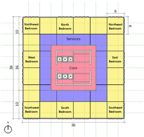
The simulation model consisted of five mid floors with the middle floor considered for data analysis (Figure 3). The results were plotted for eight perimeter zones; as shown in Figure 3. Each analysed zone was 6×6 and faced a different orientation: North, South, East, West, Northwest, Northeast, Southwest, and Southeast. The internal conditions for the simulated zones were set for a 24 h air-conditioned space, with an infiltration rate of 0.57 ach for 24 h, which are the values suggested in the Saudi Building Code Energy Conservation Requirements (SBC601). No internal gains such as equipment or occupants were considered in the simulation. The temperature set point was set according to the thermal comfort range for The Saudi Building Code Energy Conservation Requirements (SBC 601), which is 22.5–25.5°C. As for the fenestrations, a standard window size of 2.4×0.9 m was used and repeated for each simulation zone to achieve the required glazing ratio. For example, each zone is 6×6 m (36 m2), for a zone that have one exposed wall (6×3.6 m), two windows will achieve 20% glazing ratio, hence, for a zone with two exposed walls, one window in each exposed wall was placed (Figures 2 and 3). The model and zones dimensions were fixed throughout the simulations, as it was not the scope of this work to investigate the impact of different spatial configurations.
5
INPUT PARAMETERS AND
ASSUMPTIONS
[image:3.612.132.482.481.699.2]The selection of the engineering parameters used in the simu-lation was based on the elements considered for the design of
energy-efficient buildings envelopes prescribed in The Saudi Building Code Energy Conservation Requirements (SBC 601) and The Green Building Regulations and Specifications in the Emirate of Dubai (GBRS). Both building codes set the min-imum prescriptive building envelope requirements for glazing
U-value, U-value for ceiling, floor and exterior wall based on window area of gross exterior wall area, all which are con-sidered ‘engineering parameters’. The values of the para-meters were derived from existing representative case studies built in Jeddah and Abu Dhabi since they are widely employed in the current practice for residential tall buildings design in the region.
The methodology adopted consisted of adding a degree of improvement to the selected engineering parameters. The incremental change of the building opaque envelope ele-ments was done through the addition of thermal insulation products to reduce the thermal transmittance. As for the transparent elements, the degree of improvement was done through optimizing shading coefficient and thermal insula-tion, which reduce thermal transmittance and solar gains. All the decisions made were informed by the statistical data col-lected [16].
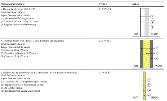
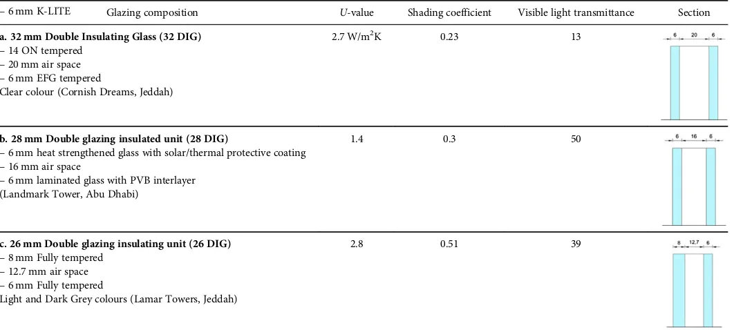
Since the focus of the simulation was an investigation of building envelope elements, the floor and roof were kept the same as a common concrete floor construction. As for the walls build-ups, the selection of the three chosen types was deter-mined by a review of the most common construction methods for residential tall buildings in the Gulf Region. Each wall type is described in Table 2 with relevant thermal characteristics. The U-value for the total wall was obtained through manual calculations. The spatial and thermal specifications of the con-struction materials were obtained from similar products in the market. Similar to the wall build-ups, the glazing composition selection was determined based on the local practice. Each type is copied from an existing building and represents the most common types in the region. Table3 illustrates the three glaz-ing composition used in the simulation. Finally, the selection of glazing ratios was based on the specifications outlined in the
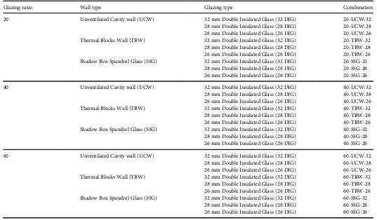
[image:4.612.314.567.59.299.2]Saudi Building Code and Dubai Green Buildings Regulations and Specifications in relation to the engineering parameters, three glazing ratios were chosen: 20%, 40% and 60% (Figure4). The glazing ratio was kept the same in all the simulated zones by following a certain grid for the window area. To better understand the simulation performed, the simulation matrix is explained in Table 4. Each combination was named as shown in the table and the same name will be used to show the results. The first number refers to the glazing ratio, the second letter arrangements are an abbreviation for the wall type, and the last number symbolizes the thickness of glazing type.
Table 1.Base case building specification.
Parameter Base case building assumptions
Total Building
Location Jeddah, Saudi Arabia
Height 223.2 m
Storeys 62
Core location Central
Building plan form Square
Residential Floor Plan
Typical floor GFA (m2) 1296
Typical floor NFA (m2) 1040
Floor Plate Efficiency 80.2%
Typical floor lease span (m) 10 Floor-to-floor height (m) 3.6
Envelope to floor ratio 0.5
Number of apartments per floor 8
[image:4.612.42.299.74.237.2]Figure 2. The base case typical residential floor plan showing the eight simu-lation zones based on orientations.
[image:4.612.319.559.354.543.2]6
ENERGY PERFORMANCE RESULTS
A total of 27 simulations were conducted representing different building envelope combinations (Table 4). The results for the dynamic thermal simulation were examined according to the orientation of the eight simulation zones in terms of annual cool-ing loads and in relation to solar gains and conductive heat gain through the opaque and transparent elements of the building enve-lope. Figure5illustrates the results comparatively and shows that the combination 20-TBW-32, highlighted in yellow, performed best in all the different orientations. As expected, the low glazing ratio (20%) and lower shading coefficient in the glazing type, and the higher insulation of the thermal blocks for the wall type follow-ing Estidama Standards contributed to the better performance. On the other hand, the un-insulated air cavity wall type (UCW) with 60% glazing ratio and higher shading coefficient (0.51) in glazing type, highlighted in red, performed worst, followed by the building envelope combinations of shadow box spandrel glass (SSG) due to the high solar gain through large glazing area coupled with worse shading properties for the glazing type. It is also visible that the corner zones (Southwest, Southeast, Northwest and Northeast) performed worse in relation to cooling loads in the same men-tioned order, due to the larger area of exposed walls from two-direction and constant solar gain from the west or east, while the North-oriented zones performed best in all the simulation results.
Looking closely at the results of the different orientations for each combination shows that in the case of the Unventilated Cavity Wall (UCW), the conductive heat gain through opaque walls contributed most to cooling loads due to the lack of wall thermal insulation. However, as the glazing ratio increases from 20% to 40% and 60%, the solar gains surpass conductive heat gains especially in the glazing type with the higher shading coefficient, which allowed more solar gain into the zone. On the other hand, using thermal insulation and replacing the wall type with the Thermal Blocks wall type (TBW) has significantly reduced the conductive heat gain through opaque element, while solar gains contributed most to the cooling loads in rela-tion to the glazing types with higher shading coefficient (26 and 28 mm glazing types). For the third wall type, Shadow Box Spandrel Glass (GSS), it is clear that solar gain is the main con-tributor to the massive increase in cooling loads due to the excessive use of glass as a wall type. Ultimately, and as expected, the addition of thermal insulation for the opaque elements can significantly solve the conductive heat gain. On the other hand, adjusting shading coefficient for the glazing elements can con-tribute hugely to solar gains even for higher glazing ratios. For example, the use of lower shading coefficient in 60% glazing ratio reduced the solar gain by up to 63%.
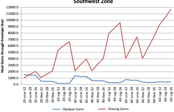
[image:5.612.40.579.70.396.2]Figures 6 and 7 illustrate the heat gains through the opaque and glazing elements of the building envelope for the North and
Table 2.Wall Construction Types for the simulation.
Wall construction types U-value Section
a. Unventilated Cavity Wall (UCW) 1.13 W/m2K
Total thickness 204 mm Layers from outside to inside (1) Aluminium Cladding (4 mm) (2) Unventilated Air Cavity (100 mm) (3) Gypsum Blocks (60×60×10 cm)
b. Thermal Blocks Wall (TBW) (as per Estidama specifications) 0.21 W/m2K Total thickness 300 mm
Layers from outside to inside (1) Concrete block (70 mm) (2) Expanded polystyrene (160 mm) (3) Concrete block (70 mm)
c. Shadow Box Spandrel Glass (SSG) (The Gate District Tower in Abu Dhabi) 0.3 W/m2K Total thickness 137 mm
Layers from outside to inside
(1) Monolithic heat strengthened glass (6 mm) (2) Rigid powder coated aluminium (1 mm) (3) Air cavity (80 mm)
Southwest zones as representative cases of the best and worst zones in relation to orientation. Comparing the results of heat gain expectantly proves, in similar patterns, that heat gain though the glazing elements is considerably higher than through the opa-que elements with direct connection to the glazing types with the higher shading coefficient. Overall, the results showed that the dif-ference between the best combination (20-tbw-32) and worst com-bination (60-ssg-26) reaches up to 77%, outlining the huge impact even simple facade design changes can make on the performance of a building.
7
CONCLUSIONS
The parametric study in this paper aimed to investigate and highlight the most significant façade ‘engineering parameters’ that impact the thermal performance of tall buildings envelope in the city of Jeddah. The results showed that due to the high
[image:6.612.108.509.63.190.2]air temperature and abundance solar radiation characterizing the climate in the region, the thermal characteristics of the glaz-ing type such as shadglaz-ing coefficient, is the dominant factor in reducing cooling energy loads in relation solar gains; in other words, lower shading coefficient can significantly decrease the solar gains even for large glazing areas. Secondly, the insulation in the wall construction type can eliminate conductive heat gain through the opaque element. Based on these findings, the difference in cooling loads energy reduction can reach up to 77%, outlining the huge impact even simple facade design changes can make on the performance of a building. The best façade combination in this simulation consists of the use of Thermal Blocks for walls and the 32mm glazing type with the lowest shading coefficient of (0.23). On the other hand, the choice of Spandrel Glass, commonly used to achieve an aesthet-ically unified slick façade has a significant negative impact on tall buildings in the hot climate of the region, dramatically increasing their solar gain and cooling loads.
Figure 4. The variation of window glazing ratio tested in the simulation for each facade orientation.
Table 3.Glazing compositions for the simulation (Source: Author).
Glazing composition U-value Shading coefficient Visible light transmittance Section
a. 32 mm Double Insulating Glass (32 DIG) 2.7 W/m2K 0.23 13
–6 mm K-LITE
–14 ON tempered
–20 mm air space
–6 mm EFG tempered
Clear colour (Cornish Dreams, Jeddah)
b. 28 mm Double glazing insulated unit (28 DIG) 1.4 0.3 50
–6 mm heat strengthened glass with solar/thermal protective coating
–16 mm air space
–6 mm laminated glass with PVB interlayer (Landmark Tower, Abu Dhabi)
c. 26 mm Double glazing insulating unit (26 DIG) 2.8 0.51 39
–8 mm Fully tempered
–12.7 mm air space
–6 mm Fully tempered
[image:6.612.43.574.244.483.2]Table 4.The simulation matrix.
Glazing ratio Wall type Glazing type Combination
20 Unventilated Cavity wall (UCW) 32 mm Double Insulated Glass (32 DIG) 20-UCW-32
28 mm Double Insulated Glass (28 DIG) 20-UCW-28 26 mm Double Insulated Glass (26 DIG) 20-UCW-26
Thermal Blocks Wall (TBW) 32 mm Double Insulated Glass (32 DIG) 20-TBW-32
28 mm Double Insulated Glass (28 DIG) 20-TBW-28 26 mm Double Insulated Glass (26 DIG) 20-TBW-26 Shadow Box Spandrel Glass (SSG) 32 mm Double Insulated Glass (32 DIG) 20-SSG-32
28 mm Double Insulated Glass (28 DIG) 20-SSG-28 26 mm Double Insulated Glass (26 DIG) 20-SSG-26
40 Unventilated Cavity wall (UCW) 32 mm Double Insulated Glass (32 DIG) 40-UCW-32
28 mm Double Insulated Glass (28 DIG) 40-UCW-28 26 mm Double Insulated Glass (26 DIG) 40-UCW-26
Thermal Blocks Wall (TBW) 32 mm Double Insulated Glass (32 DIG) 40-TBW-32
28 mm Double Insulated Glass (28 DIG) 40-TBW-28 26 mm Double Insulated Glass (26 DIG) 40-TBW-26 Shadow Box Spandrel Glass (SSG) 32 mm Double Insulated Glass (32 DIG) 40-SSG-32
28 mm Double Insulated Glass (28 DIG) 40-SSG-28 26 mm Double Insulated Glass (26 DIG) 40-SSG-26
60 Unventilated Cavity wall (UCW) 32 mm Double Insulated Glass (32 DIG) 60-UCW-32
28 mm Double Insulated Glass (28 DIG) 60-UCW-28 26 mm Double Insulated Glass (26 DIG) 60-UCW-26
Thermal Blocks Wall (TBW) 32 mm Double Insulated Glass (32 DIG) 60-TBW-32
28 mm Double Insulated Glass (28 DIG) 60-TBW-28 26 mm Double Insulated Glass (26 DIG) 60-TBW-26 Shadow Box Spandrel Glass (SSG) 32 mm Double Insulated Glass (32 DIG) 60-SSG-32
[image:7.612.38.575.404.718.2]28 mm Double Insulated Glass (28 DIG) 60-SSG-28 26 mm Double Insulated Glass (26 DIG) 60-SSG-26
The findings also emphasized that solar gains are the highest contributor to cooling loads, hence, the reliance on a prescriptive approach for building envelope‘engineering parameters’ specifica-tions does not necessarily achieve the required reduction of solar gains, and the development of the ‘design parameters’, such as shading elements, could have a significant impact on cooling energy loads.
Further work consisting of parametric studies and data measurements that aim to define the most promising solu-tion focusing on design parameters such as façade shading
solutions, is necessary to identify to what extent can an alter-native approach improve the environmental performance of the residential tall building type in the hot climate of the Gulf Region.
ACKNOWLEDGEMENTS
[image:8.612.127.486.66.297.2]This research was supported by University of Nottingham and financially funded by King Abdulaziz University in Saudi Arabia.
Figure 6. Comparison of the heat gain (kw) through the opaque and glazing elements of building envelope for the North zone.
[image:8.612.126.485.337.568.2]REFERENCES
[1] Lahn G, Stevens P.Burning Oil to Keep Cool: the Hidden Energy Crisis in Saudi Arabia. The Royal Institute of International Affairs, London, 2011. [2] CTBUH. 2014. The Skyscraper Center [Online]. Council on Tall Buildings
and Urban Habitat.
[3] Brown G, Dekay M. Sun, Wind & Light: Architectural Design Strategies. John Wiley & Sons, Inc, USA, 2001.
[4] Baker N, Steemers K. LT method 3.0—a strategic energy-design tool for Southern Europe.Energy Build1996;23:251–256.
[5] Haase, M, Amato, A. 2006. Sustainable Facade Design for Zero Energy Buildings in the Tropics. In: The 23th Conference on Passive and Low Energy Architecture. Geneva, Switzerland: PLEA.
[6] Al-Hosany, N. 2002. Sustainable Facade Design and Virtue in Incarceration Architecture: the Case of Prison Buildings in Abu Dhabi, PhD Thesis, University of Newcastle upon Tyne.
[7] Meir, I, Peeters, D, Halasah, S, Garb, Y, Davies, J. Green Buildings Standards in MENA: an assessment of regional constraints, needs and trends. In: PLEA 29th Conference, Sustainable Architecture for a Renewable Future, 10–12 September 2013. Munich, Germany, 2013.
[8] CONSTRUCT [Online] 2012. Updated Building Regulations in the GCC. Venture Middle East.
[9] SBC601.The Saudi Building Code Energy Conservation Requirements. The Saudi Building Code National Committee, Saudi Arabia, 2007.
[10] GBRS.Green Building Regulations & Specifications. Government of Dubai, Dubai, 2010. In: AUTHORITY, D. E. A. W. (ed.).
[11] ESTIDAMA. 2010. Pearl Building Rating System [Online].
[12] GSAS.Commercial and Residential GSAS Training Manual. Gulf Organisation for Research and Development, Qatar, 2013.
[13] Pisello A, Goretti M, Cotana F. A method for assessing buildings’energy efficiency by dynamic simulation and experimental activity.Applied Energy
2012;97:419–429. [14] EDSL Tas, 2015, [online]
[15] Hamza, N. 2004. The Performance of Double Skin Facades in Office Building Refurbishment in Hot Arid Areas, PhD Thesis, University of Newcastle upon Tyne.