Abstract-- This paper presents the comparative study and optimal design of a transverse flux linear machine with different PM configurations, viz. surface-mounted and consequent-pole, in which the consequent-pole version is firstly proposed. Firstly, the effect of variation of the main design parameters on both topologies are studied. Then, the multi-objective optimization method based on genetic algorithm combined with response surface methodology (RSM) is adopted to realize the optimal design of these two topologies and Pareto front solutions will be obtained. Finally, the characteristics of these two topologies are analyzed and compared, with particular regard to the advantages and disadvantages of the consequent pole topology.
Index Terms-- consequent-pole; multi-objective optimization; response surface methodology (RSM); transverse flux linear machine.
I. INTRODUCTION
Linear drive systems using linear electrical machines without rotary-to-linear mechanical conversion offer many advantages over their rotary configuration counterparts, such as excellent dynamic characteristics, higher acceleration, and easy maintenance [1, 2]. The demand for linear electrical machines has increased for applications in recent years. Of the various types of linear machine, the transverse flux permanent magnet linear machine (TFPMLM) is considered advantageous for linear drive applications due to its relative higher force density due to the fact that it can realize the decoupling between electric loading and magnetic loading.
Various topologies of TFPMLM have been presented to deal with the problems of its complex structure and large flux leakage, since the first prototype of transverse flux machine was proposed by Weh [3-6]. In earlier works, a tubular staggered tooth transverse flux PM linear machine (TFPMLM) is proposed to address the problem of complex structure, which is characterized by large force density and simple structure [7, 9].
However, the optimal design of the machine was not studied. Conventional surface-mounted TFPMLMs typically contain significant quantities of permanent magnet (PM) material covering the entire secondary active surface, which results in high material costs. Consequent-pole machines have also been developed [8], using half the amount of PM material, with reluctance torque/force from the consequent pole structure being used to attempt to give similar torque/force density to the full PM secondary while
improving mechanical stiffness of the machine.
This paper presents the comparative study and optimal design of a TFPMLM with different PM configurations, viz. surface-mounted (S-TFPMLM) and consequent-pole (CP-TFPMLM), in which the consequent-pole version is firstly proposed. The effect of variation of the key design parameters on both topologies are comparatively studied. In order to have a decent comparison between these two topologies, global optimization is required. Due to the fact that the general optimization method of single factor analysis [4, 7] cannot find the global optimum scheme and conventional direct optimization algorithms combined with 3-D FEM are quite time-consuming, we adopt a multi-objective method combined with response surface methodology (RSM) to deal with this problem, which can be efficient and accurate [10, 11]. The multi-objective optimization method based on Non-dominated Sorting Genetic Algorithm-II (NSGA-II) combined with response surface methodology (RSM) is adopted to realize the optimal design of these two topologies and Pareto front solutions will be obtained. Finally, the characteristics of these two topologies are analyzed and compared, with particular regard to the benefits and disadvantages of the consequent pole topology.
II. MODELS
A. Structure
Fig.1 shows the schematic diagram of the overall three-phase schematic structure of the TFPMLM, of which adjacent phases are arranged by (2k-2/3) pole pitch displacement in axial direction, where k is a non-negative integer, here, k=2. The schematic structure of one phase of S-TFPMLM and CP-TFPMLM is shown in Fig. 2. Each phase has j primary cores, where j is a non-negative integer, here, j=2, and there are non-magnetic rings between primary cores for structural support. Each stator core has 2n teeth, where n is a non-negative integer, here, n=4. There is no unbalanced force in the linear bearing due to the symmetry of the magnetic circuit, which facilitates the manufacturing process and largely improve the mechanical stiffness of the machine.
The CP-TFPMLM (Fig.2 (b)) has the same primary layout as the S-TFPMLM (Fig.2 (a)) but a consequent-pole PM configuration on the secondary. Such a topology can improve the mechanical stiffness of the secondary and only
Comparative Study and Optimal Design of
Alternative PM Configuration Transverse
Flux Linear Machine
Shaohong Zhu
1, 2, Tom Cox
1, 2, Chris Gerada
1, 2, and Zeyuan Xu
21 Institute for Aerospace Technology, University of Nottingham, Innovation Park, Nottingham. NG7 2TU, UK 2Department of Electrical and Electronic Engineering, University of Nottingham, University Park, Nottingham, NG7 2RD, UK
uses half the number of PMs over the S-TFPMLM. The consequent pole structure also has significant drawbacks, including a potential weakening of the PM flux, and a change in the PM flux distribution. In addition, the consequent-pole configuration will lead to a significant increase in the armature flux leakage which will decrease the average thrust force and reduce the power factor, resulting in lager converter VA rating and converter losses.
Fig. 1 Overall structure of three phase TFPMLSM
(b) (a)
PMs
Primary cores
Secondary core Shaft
Coils
Same Polarity of PMs
Lpm
L hm
Fig. 2 Schematic structure of one phase machine (a) TFPMLM (b) CP-TFPMLM
B. Operational Principle
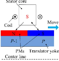
[image:2.595.309.533.232.378.2] [image:2.595.59.290.313.431.2] [image:2.595.309.534.404.553.2] [image:2.595.307.537.583.733.2]Taking the S-TFPMLM as an example, the armature magnetic field is generated when the winding is fed with a constant current, viz. south pole or north pole, as shown in Fig. 3. The translator as pictured in Fig. 3 will move right as the poles attempt to align, and move to a position in which the flux generated from PM and armature winding will have the same direction. An inversion of excitation current will force the translator to move to the left. As a result, the translator moves along the z-direction when a suitable alternating current is fed to the armature winding [7, 9].
Fig. 3. Side view of TFPMLSM
III. INFLUENCE OF MAIN DESIGN PARAMETERS
The flux distribution of CP-TFPMLM is changed over the S-TFPMLM. It can be noted that there are two series magnets in each main magnetic circuit for the conventional surface-mounted TFPMLM, and only one magnet for the consequent pole TFPMLM configuration. In the consequent pole case, the magnetic reluctance of the main magnetic circuit is significantly reduced which results in increased flux leakage, especially armature flux leakage. Fig. 4-6 show the comparisons of the no load flux linkage, no load EMF and thrust force of both machines with the same design dimensions and the characteristics of both machines have been summarized in TABLE I.
Fig. 4 Comparison of no load flux linkage of one phase
[image:2.595.113.237.625.753.2]Fig. 5 Comparison of no load EMF of one phase
TABLE I
Comparison of characteristics of both machines
It is obvious that the S-TFPMLM exhibits a higher magnitude of flux linkage, EMF and thrust force than the CP-TFPMLM. The thrust force of CP-TFPMLM is decreased by 26.7% compared to the S-TFPMLM, but the former does only use half of magnets, which means the thrust per magnet volume of the consequent pole machine is better.
On the other hand, it is necessary to analyze the variation of main design parameters on the electromagnetic performance of both topologies and make a comparison. Due to the characteristic of 3-D flux distribution in both machines, the 3-D finite element method (FEM) has been used to accurately predict the electromagnetic characteristics using Ansys’ Maxwell software package. For a given outer diameter, the electromagnetic performance of this type of transverse flux linear machine is significantly influenced by three main design parameters including PM magnetization length hm, axial length of PMs Lm, and axial length of the primary iron core L, as shown in Fig. 2(b). Hence the effect of these three parameters on the average thrust force and thrust per magnet volume will be investigated by 3-D FEM.
Fig. 7 depicts the average thrust force and thrust per magnet volume of both topologies, CP-TFPMLM and S-TFPMLM, as a function of L when hm and Lm is 4 and 7mm, respectively. The thrust force for CP-TFPMLM increases when L is changing from 5 to 7mm and then decreases after that; and the optimal length is 7 mm which result in a maximum thrust force. A similar trend of thrust force can be found for S-TFPMLM, except that the rate of growth is much lower when L varies from 5 to 7mm. On the other hand, it can be easily observed that general trends in variation of the average thrust force and thrust per magnet volume for each machine are the same, which is due to the magnet volume not changing when L varies. Generally, the thrust force of CP-TFPMLM is much lower than that of S-TFPMLM, whereas the thrust per magnet volume of former is much larger than that of latter.
Fig. 8 depicts the average thrust force and thrust per magnet volume of both topologies as a function of hmwhen both L and Lm are 7 mm. The variation tendencies of average thrust forces for both machines are quite similar, proportionally increasing when hm increases, and the rate of growth is decreasing which is caused by the magnetic saturation. The thrust force of CP-TFPMLM is far lower than that of S-TFPMLM at each point. On the other hand, the variation trends for thrust per magnet volume for both machines are quite similar as well, decreasing when hm increases and with thrust per magnet volume of the CP-TFPMLM much larger than that of S-CP-TFPMLM. The optimal length hm for S-TFPMLM and CP-TFPMLM is 4
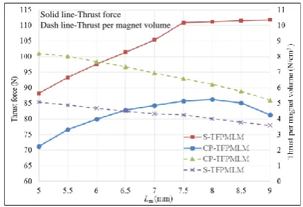
and 3.5mm, respectively, which results in larger thrust force and large thrust per magnet volume at the same time. Fig. 9 shows the average thrust force and thrust per magnet volume of both two topologies as a function of Lm when Land hm are 7 and 4 mm, respectively. A similar trend as in Fig 8 can be found. The thrust force for S-TFPMLM is increasing when Lm varies from 5 to 7.5mm, and then tends to level off due to saturation. However, the thrust force of the CP-TFPMLM increases at lower values of Lm and then decreases at higher values, which is caused by the increasing flux leakage when Lm increases. The thrust per magnet volume of both topologies is proportionally decreasing when Lm increases. Therefore, the optimal length for both machines is 7.5mm which results in larger thrust force and relatively larger thrust per magnet volume at the same time.
Solid line-Thrust force
[image:3.595.313.528.260.406.2]Dash line-Thrust per magnet volume
Fig. 7. Thrust force as a function of axial core length L
Solid line-Thrust force
Dash line-Thrust per magnet volume
Fig. 8. Thrust force as a function of PM magnetization length hm
Solid line-Thrust force
Dash line-Thrust per magnet volume
Fig. 9.Thrust force as a function of axial length of PMs Lm Magnitude of
flux linkage (Wb)
Magnitude of EMF
(V)
Average Thrust force (N)
Force ripple (%)
CP-TFPMLM 0.031 10 87.6 2.5
[image:3.595.312.527.430.575.2] [image:3.595.311.531.603.753.2]It can be observed that the thrust per magnet volume of CP-TFPMLM is always much higher than that of S-TFPMLM under each specific design dimension or parameter combination, and in contrast, the thrust force of the consequent pole machine is much lower. From this point, it is hard to draw conclusion of which one is better. Therefore, it is necessary to look at global optimization of both machines and make a comprehensive performance comparison between the two optimized machines.
IV. OPTIMIZATION AND COMPARISON
In order to quantitatively evaluate and compare the characteristics of the S-TFPMLM and CP-TFPMLM in the aspects of force capabilities and PM cost, two different topologies with the same size will be considered and optimized.
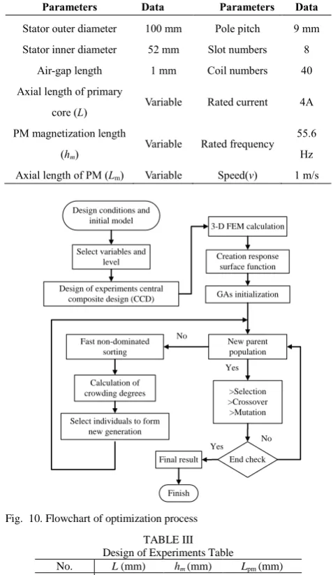
The main dimensions of the two topologies of the machine are summarized in TABLE II. It should be noted the basic geometric dimensions such as outer diameter and pole pitch of the two topologies of the machine are the same, except three variable dimensions. The effects of independent variation of three leading design dimensions, axial length of primary core (L), PM magnetization length (hm) and axial length of PM (Lpm) have been investigated in Part III, which shows that these parameters have a significant influence on the electromagnetic performance of both machines. Therefore the two topologies of the machine will be optimized considering variation of these three parameters. The optimization is addressed by maximizing the thrust force and thrust per magnet volume at the same time.
A multi-objective optimization method based on NSGA-II combined with response surface methodology (RSM) is adopted to realize the optimal design of these two machines, and the optimization process is shown in Fig. 10.
A. RSM
The response surface methodology (RSM) is a statistical fitting method using design of experiment (DOE), which can be used to build a polynomial model of output with respect to many input variables through a small number of design experiments [9]. Here, 3D-FEM is used as numerical experiments to provide the response. The general form of RSM can be written as
𝑌 = f(𝑥, 𝜃) (1) where the variables (X1, X2,. . ., Xk) in (1) are centered and scaled design units, which means their range is between -1 and 1. The true response function f is unknown and very complicated, so it is approximated by using response function. Normally, the response function can be a first-order or second-first-order polynomial model. In some cases, a higher-order polynomial can be chosen to get a more accurate approximation. In (2) a third-order polynomial model is shown:
𝑌 = 𝛽0+ ∑𝑘𝑗=1𝛽𝑗𝑥𝑗+ ∑𝑘𝑗=1𝛽𝑗𝑗𝑥𝑗2+ ∑𝑘𝑖≠𝑗𝛽𝑖𝑗𝑥𝑖𝑥𝑗+ ∑𝑘 𝛽𝑗𝑗𝑥𝑖𝑥𝑗2
𝑗=1 + ∑𝑘𝑗=1𝛽𝑗𝑗𝑥𝑗3 (2) where β representsthe regression coefficients and ε is a random error treated as statistical error. This model can also be written as matrix form:
𝐘 = 𝜷𝐗 + 𝛆 (3)
where X is a matrix of independent design variables, β is a vector of regression coefficients, and ε is a vector of random error.
The least square method, which aims to minimize the sum of the squares of the random errors, is employed to estimate unknown vector β, which can be written as 𝜷̂ = (𝐗′𝐗)′𝐗′𝐘 (4) 𝐘̂ = 𝐗𝜷̂ (5).
TABLE II
Main Design Specifications and Geometries of Model Parameters Data Parameters Data
Stator outer diameter 100 mm Pole pitch 9 mm
Stator inner diameter 52 mm Slot numbers 8
Air-gap length 1 mm Coil numbers 40
Axial length of primary
core (L) Variable Rated current 4A
PM magnetization length
(hm)
Variable Rated frequency 55.6 Hz
Axial length of PM (Lm) Variable Speed(v) 1 m/s
Design conditions and initial model
Select variables and level
Design of experiments central composite design (CCD)
3-D FEM calculation
Creation response surface function
GAs initialization
New parent population
>Selection >Crossover >Mutation
End check No Yes
Final result
Finish
Yes Fast non-dominated
sorting
Calculation of crowding degrees
Select individuals to form new generation
[image:4.595.301.540.195.607.2]No
[image:4.595.319.518.575.764.2]Fig. 10. Flowchart of optimization process
TABLE III Design of Experiments Table
No. L (mm) hm (mm) Lpm (mm)
1 5 2 5
2 8 2 5
3 5 6 5
4 8 6 5
5 5 2 9
6 8 2 9
7 5 6 9
8 8 6 9
9 5 4 7
10 8 4 7
11 6.5 2 7
12 6.5 6 7
13 6.5 4 5
14 6.5 4 9
15 6.5 4 7
16 7 4 7
B. Model Development
The classical central composite design (CCD) method is adopted to design a set of experiments, which is listed in TABLE III. It should be noted that last two arrays are added by the authors to improve the accuracy of the RSM. Analysis results of each experiment are obtained through 3-D FEA.
A cubic polynomial is here to be used to fit the thrust force and thrust per magnet volume of both machines. The coefficient of determination R2 of the two response models for thrust force of both machines is 0.9958 and 0.9858, so the response models are well built, and the statistical cubic polynomial models of average thrust force for both S-TFPMLM and CP-S-TFPMLM, for example, can be expressed as (6) and (7). It should be noted that the variables in the polynomials are centered and scaled design units, which means their values are between -1 and 1.
Expression of thrust force for S-TFPMLM
𝐹1 = 105.08 + 1.09 ∗ 𝐿 + 5.11 ∗ ℎ𝑚 + 11 ∗ 𝐿pm − 0.34 ∗ L ∗ ℎ𝑚 + 0.33 ∗ 𝐿 ∗ 𝐿pm + 0.45 ∗ ℎ𝑚 ∗ 𝐿pm − 2.89 ∗ 𝐿2− 4.66 ∗ ℎ𝑚2− 4.41 ∗ 𝐿𝑝𝑚2
(6).
Expression of thrust force for CP-TFPMLM
𝐹2 = 83.45 + 1.43 ∗ 𝐿 + 9.02 ∗ ℎ𝑚 + 7.88 ∗ 𝐿pm − 0.19 ∗ L ∗ ℎ𝑚 + 0.066 ∗ 𝐿 ∗ 𝐿pm − 0.19 ∗ ℎ𝑚 ∗ 𝐿pm −6.23 ∗ 𝐿2− 2.36 ∗ ℎ𝑚2− 3.73 ∗ 𝐿𝑝𝑚2
(7).
C. Optimization Results
For the multi-objective optimization in this work, we use a controlled elitist multi-objective genetic algorithm (MOGA, a variant of NSGA II) in MATLAB. Except for population size, other algorithm parameters are the default values, e.g., Pareto fraction is 0.35. The default population size is 15*D, however, in order to have more Pareto points, population size was chosen to be 90.
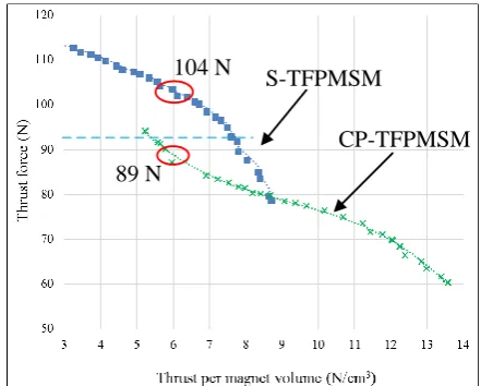
The Pareto optimal solutions obtained from multi-objective optimization based on the polynomial model built from previous parts are shown in Fig. 11. As we can see, for both machines the thrust force and thrust per magnet volume cannot be maximum at the same time, which is reasonable due to the conflict between the machine performance and cost. In addition, the thrust force generated from CP-TFPMLM is always lower than that from S-TFPMLM under the same thrust per magnet volume. For example, the S-TFPMLM offers thrust force of 107 N while the CP-TFPMLM can only have a thrust force of 90 N under the same thrust per magnet volume of about 6 N/cm3. Alternatively, under the same requirement of average thrust force, the thrust per magnet volume of S-TFPMLM is always larger than that of CP-S-TFPMLM.
Therefore, the CP-TFPMLM has no advantages over S-TFPMLM in the PM cost which is mainly because the consequent-pole PM configuration has only half MMF compared with that of S-TFPMLM, although the magnetic reluctance of main magnetic circuit is also reduced. However, the most important reason is that no reluctance force/toque exists in this transverse flux linear machines as in the radial or axial machine topologies since the value of d- and q- axis inductance of CP-TFPMLM is very close, viz., no saliency effect, as shown in Fig. 12. The value of
Ld and Lq is 5.4 and 6.5 mH, respectively, and the salient ratio is then 1.12, which is almost equal to 1. In addition, transverse flux machines with consequent-pole PM configuration increase the flux leakage in both the longitudinal and transverse directions as well.
D. Comparison
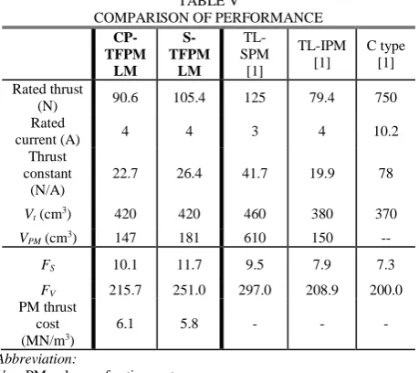
A performance comparison of CP-TFPMLM, S-TFPMLM, and other various types of linear machines is shown in TABLE IIIIV, showing that the TFPMLMs performance is highly competitive with other forms of linear machine. It can be observed that the thrust per active PM volume is almost the same for both machines whereas the S-TFPMLM exhibits higher thrust force over CP-TFPMLM. The force density per active air-gap surface of C-TFPMLM is 15.8% lower than that of S-TFPMLM but is still 27.8% larger than that of TL-IPM. Also, the force per active volume is larger than that of TL-IPM and C-TYPE, whereas lower than that of TL-SPM. Therefore, it is confirmed that the proposed transverse flux linear machine is close to the one achieved through the latest state-of-the-art in linear machine technologies.
104 N
89 N
S-TFPMSM
[image:5.595.310.531.327.504.2]CP-TFPMSM
[image:5.595.308.533.532.683.2]Fig. 11 Pareto points of MOGA of both topologies
Fig. 12 Diagram of d- and q- axis inductance of CP-TFPMLM
V. CONCLUSIONS
conventional surface-mounted configuration transverse flux PM linear machine have been made using the NSGA-II algorithm combined with RSM. The comparison of multi-objective optimization results shows that the CP-TFPMLM offers no advantages in PM cost except the improved mechanical stiffness over a conventional S-TFPMLM for a given output force. The key reason for this is that, unlike in consequent-pole radial or axial machine topologies, no significant reluctance force can be developed in the consequent-pole linear transverse flux machine. Nonetheless, this machine still exhibit better thrust capabilities over other types of linear machine.
TABLE V
COMPARISON OF PERFORMANCE
CP-TFPM LM
S-TFPM
LM
TL-SPM
[1]
TL-IPM [1]
C type [1]
Rated thrust
(N) 90.6 105.4 125 79.4 750 Rated
current (A) 4 4 3 4 10.2 Thrust
constant (N/A)
22.7 26.4 41.7 19.9 78
Vt (cm3) 420 420 460 380 370
VPM (cm3) 147 181 610 150 --
FS 10.1 11.7 9.5 7.9 7.3 FV 215.7 251.0 297.0 208.9 200.0
PM thrust cost (MN/m3)
6.1 5.8 - - -
Abbreviation:
VPM: PM volume of active part.
FS: Thrust force per active air-gap area(unit, kN/m2) [7] FV: Thrust force per active external volume (unit, kN/m3) [7]
ACKNOWLEDGMENT
This work is funded by the INNOVATIVE doctoral programme. The INNOVATIVE programme is partially funded by the Marie Curie Initial Training Networks (ITN) action (project number 665468) and partially by the Institute for Aerospace Technology (IAT) at the University of Nottingham. 8200504
REFERENCES
[1] J. S. Shin, R. Watanabe, T. Koseki, and H. J. Kim, “Transverse flux type cylindrical linear synchronous motor for large thrust using generic armature cores for rotary machinery,” IEEE Trans. Ind. Electron., vol.61, no. 8, pp. 4346-4355, 2014.
[2] J. F. Eastham, “Novel synchronous machines: linear and disc,” Proc. Inst. Elect. Eng., vol. B-137, pp. 49-58, 1990. [3] J. S. Shin, R. Watanabe, T. Koseki, and H. J. Kim, “Practical
design approach of a transverse flux linear synchronous motor for compact size, small mover weight, high efficiency, and low material cost,” IEEE Trans. Magn., vol. 51, no. 3, pp. 1-4 , 8200504, 2015.
[4] M. Zhao, Q. Wang, J. Zou, and G. Wu, “Development and analysis of tubular transverse flux machine with permanent-magnet excitation,” IEEE Trans. Ind. Electron., vol. 59, no. 5, pp. 2198-2207, 2012.
[5] D. Kang, “Increasing of thrust force in transverse flux machine by permanent-magnet screen,” IEEE Trans. Magn., vol. 41, no. 5, pp.1952-1955, 2005.
[6] Q. Lu, Y. Li, X. Huang, and Y. Ye, “Analysis of Transverse-Flux Linear Switched-Transverse-Flux Permanent Magnet Machine,” IEEE Trans. Magn. vol. 51, no. 11, 8108804, 2015 [7] P. Zheng, S. Zhu, B. Yu, L.M. Cheng, and Y.H. Fan,
“Analysis and Optimization of a Novel Tubular Staggered-Tooth Transverse-Flux PM Linear Machine,” IEEE Trans. Magn., vol. 21, no. 11, 8111304, 2015.
[8] S. Chung, J. Kim, Y. Chun, et al, “Fractional Slot Concentrated Winding PMSM With Consequent Pole Rotor for a Low-Speed Direct Drive: Reduction of Rare Earth Permanent Magnet,” IEEE Trans. Energy Conv., vol. 30 no. 1, pp.103-109, 2015.
[9] S. Zhu, P. Zheng, B. Yu, L. Cheng and W. Wang, “Performance analysis and modeling of a tubular staggered-tooth transverse-flux PM linear machine,” Energies, vol. 9 no. 3, 163, 2016.
[10]Hasanien H M. “Particle Swarm Design Optimization of Transverse Flux Linear Motor for Weight Reduction and Improvement of Thrust Force,” IEEE Trans. Ind. Electron., vol. 58 no. 9, pp. 4048-4056, 2011.